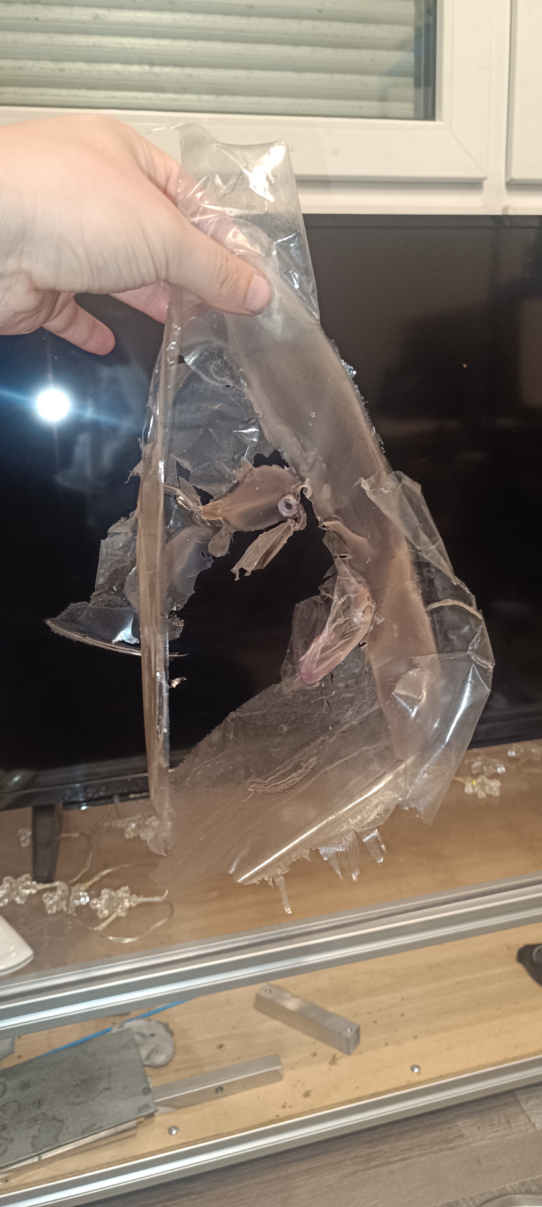
Until now, I used a mix of polyvinyl butyral and ethanol as ink for the printer, and even though PVB worked well for regulating the viscosity of the mix, the dried-up ink layer had bad adhesion properties so that it was constantly peeling off into flakes which gave it a very dirty look.
PVB / Ethanol InkThe PVB Layer was easy to peel off
Because of that, I started searching for other ethanol-based inks.
Shellac
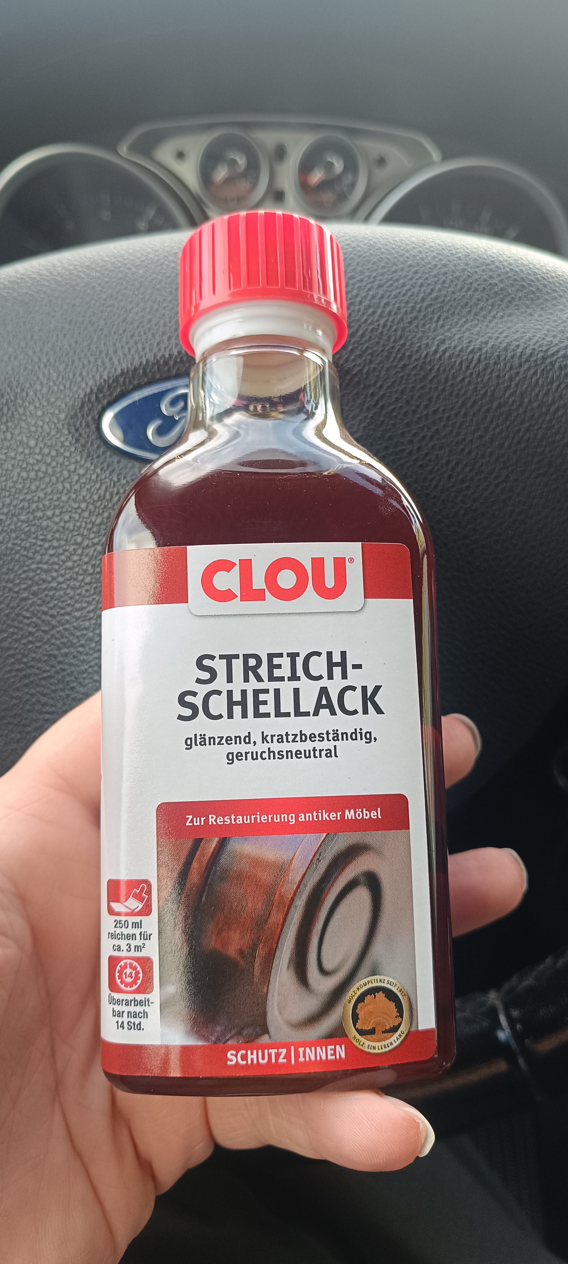
The first thing I found was shellac, which was often used as an alcohol-based furniture varnish in the past.
So, I went to the hardware store to get a small bottle of it for testing out the surface finish.
Bottle of Shellac from the Hardware Store
To test for the surface quality, I poured a small amount of it into the drip tray and let it dry.
After waiting some time, I checked the surface quality, and it looked very promising.
The shellac made a smooth, clear, shiny, and nonsticky surface with good adhesion to the stainless steel of the drip tray.
Since the varnish is alcohol-based, it was also possible to fill up the bottom of the tray with ethanol and let it dissolve the shellac, which makes cleaning it up very easy.
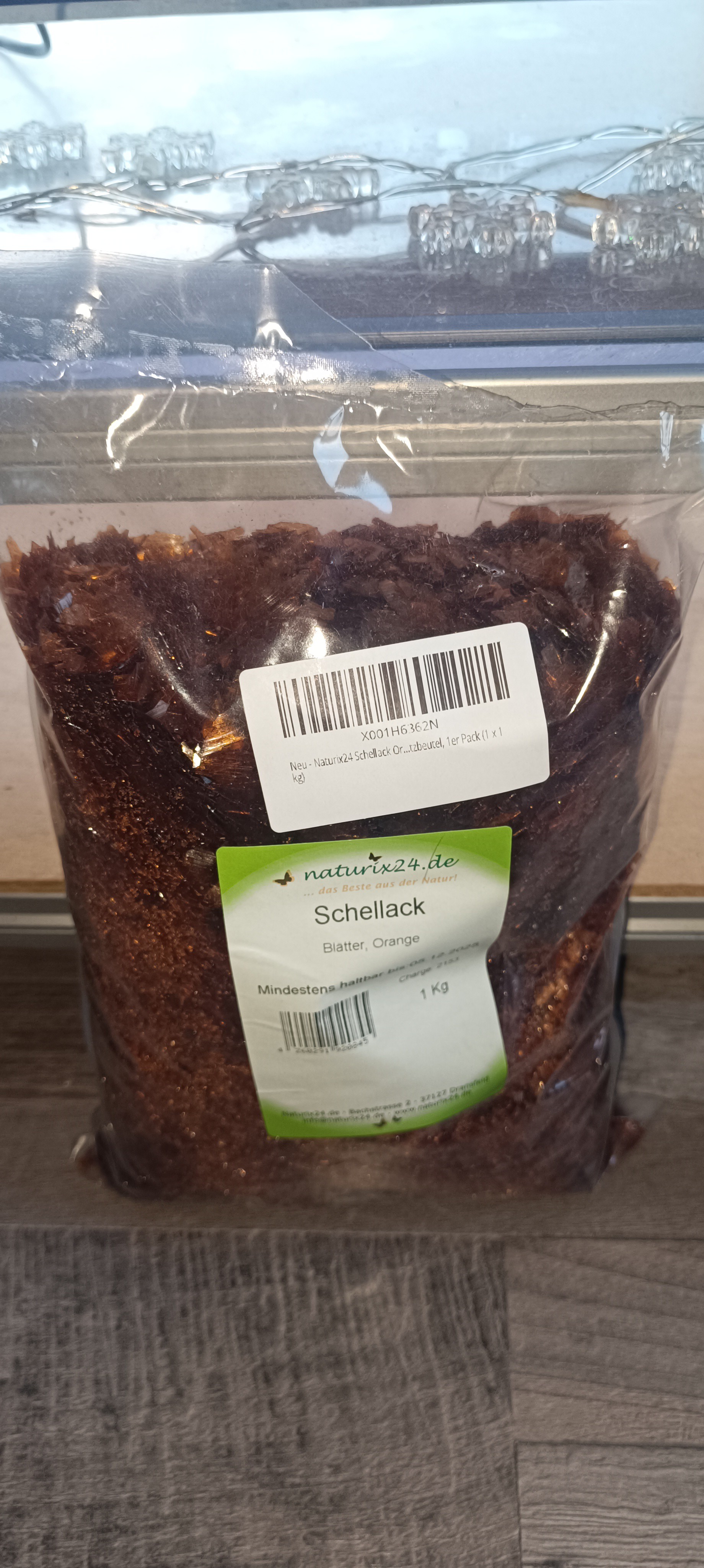
So, I ordered a bag of shellac for loading it into the printer.
Bag of ShellacMixing Ethanol with Shellac
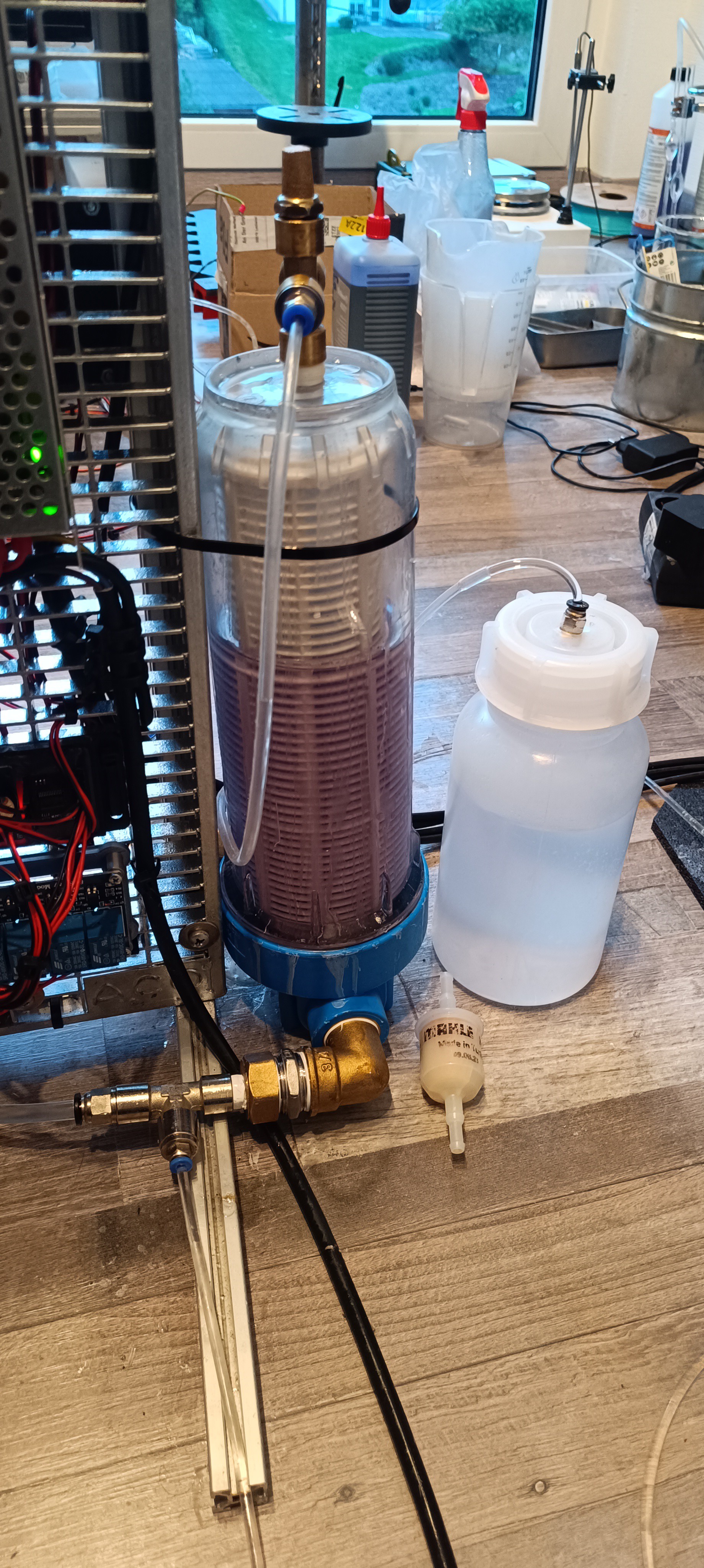
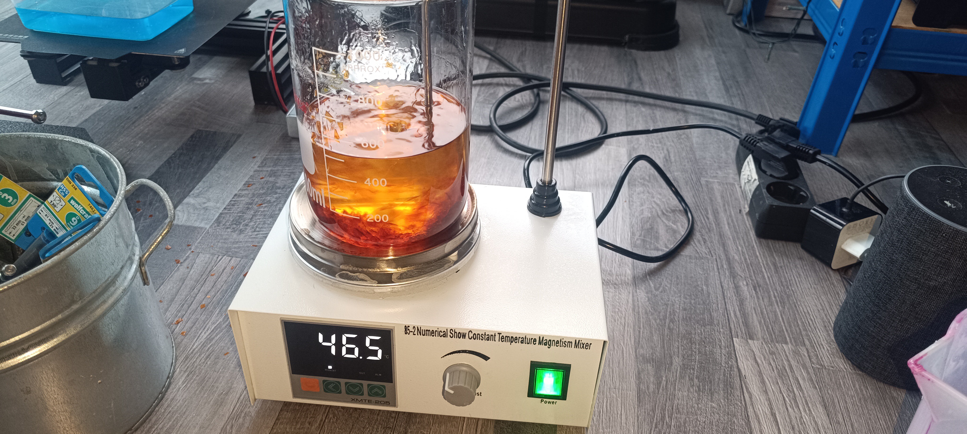
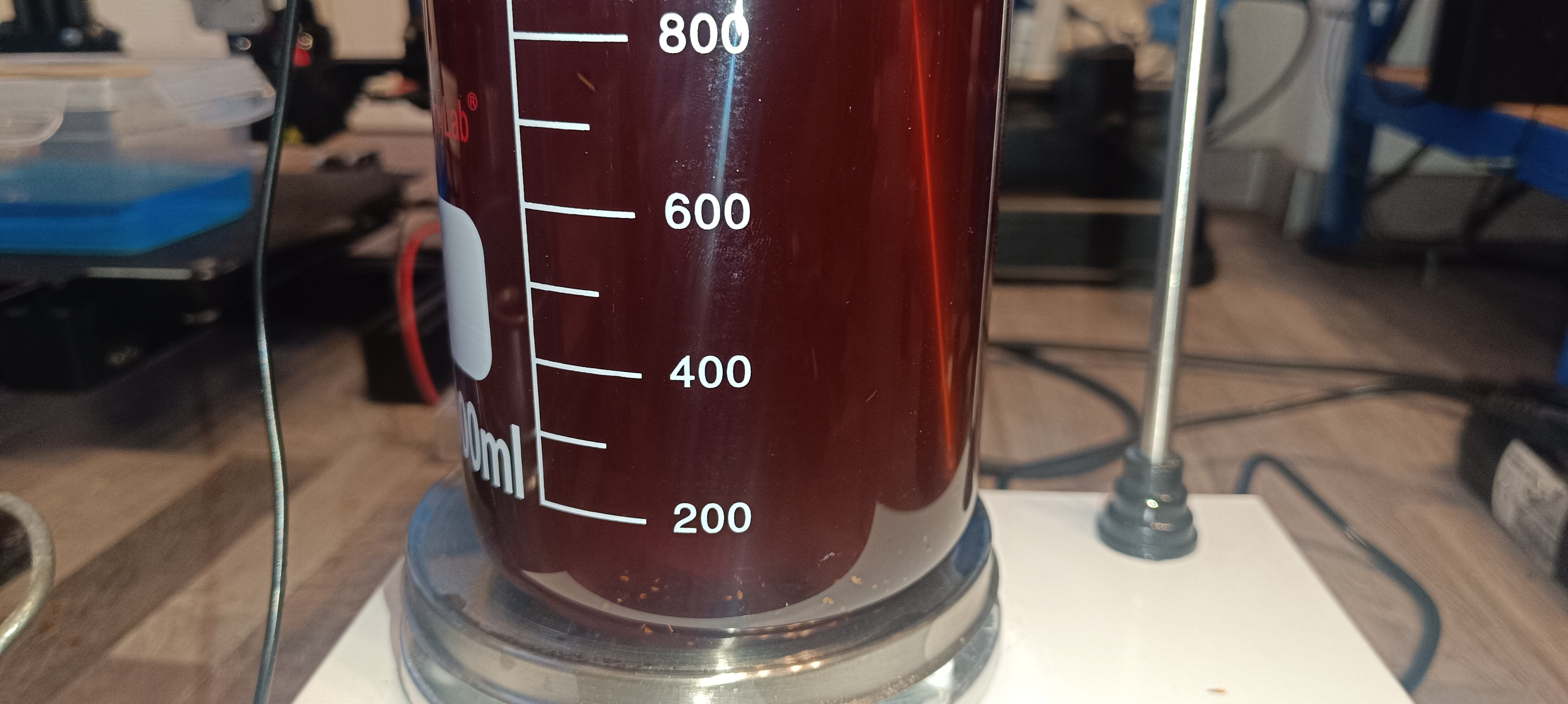
Higher Concentration gives the Ink a brownish ColorRunning the Printer with Shellac
It turned out that the shellac flakes were easy to mix with ethanol, and depending on the concentration, the color reached from orange to dark brown. It also worked well to change the viscosity based on the concentration.
When testing the charge + feedback signal it also worked as well as before.
All in all, it can be said that shellac-based ink is superior to PVB ink with a nice surface finish and an easy preparation process.
The only drawback of it could be the brown color and the fact that shellac is made by shellac lice, which could maybe raise ethical concerns.
For this reason, I continued testing out other inks.
Plant-based Varnish
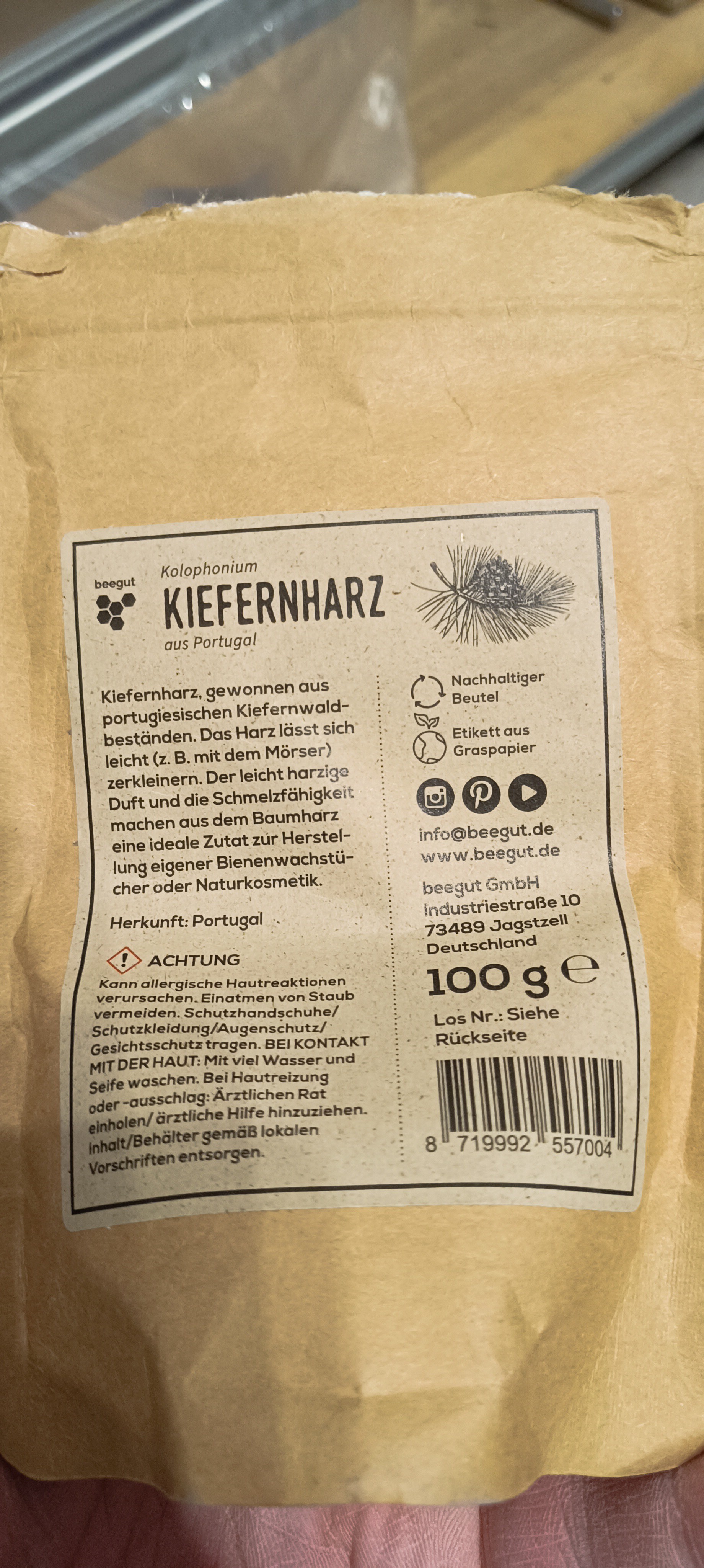
The next thing I tried was colophony/pine rosin.
Colophony / Pine Rosin
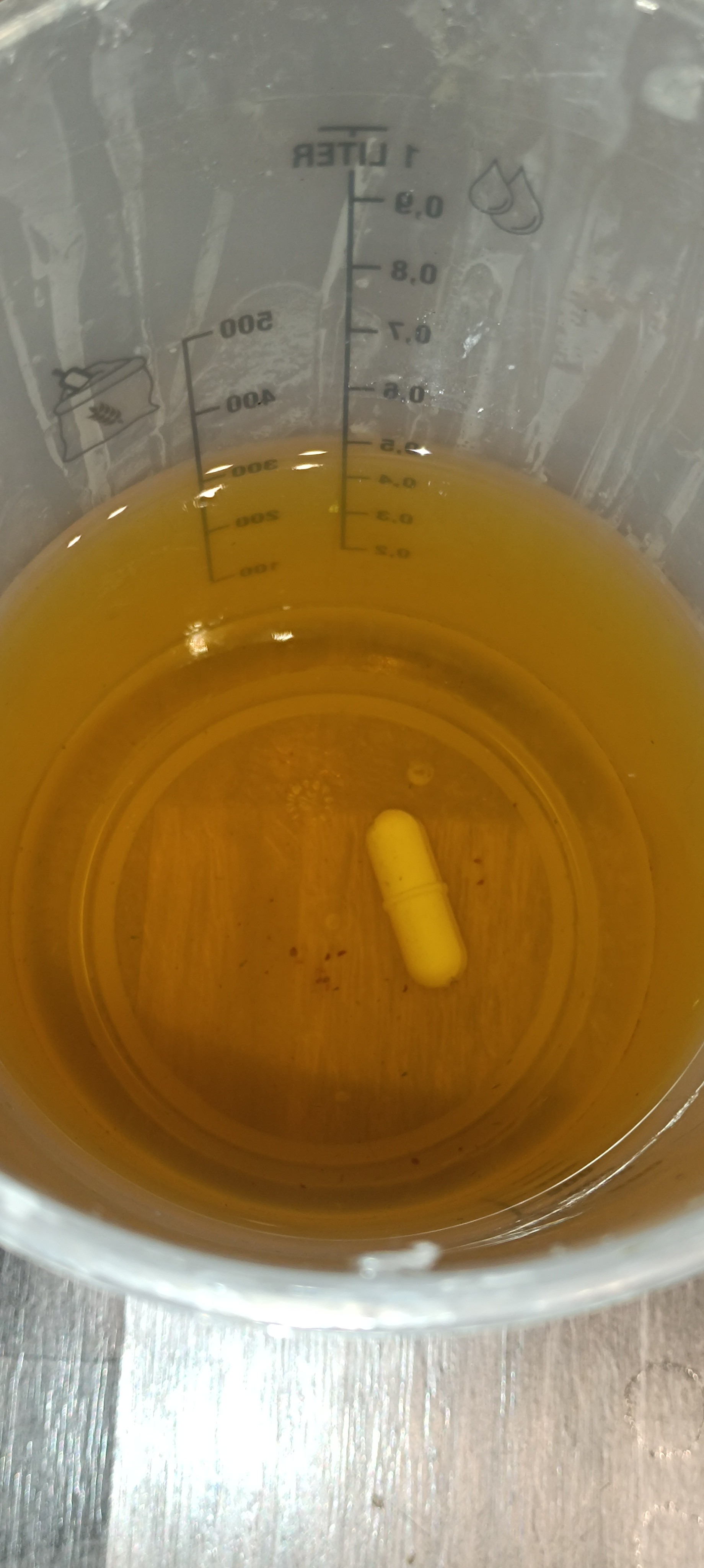
Dissolved ColophonyClear / Yellow Color Colophony Ink
The good thing with colophony was that it dissolved very well when mixed with ethanol and the color was much more clear compared to the shellac.
But when I then tested out the surface finish in the drip tray as with the shellac before, I quickly realized that this mixture would not be suitable for using it in the printer.
While the surface finish looked ok at first glance, it turned out that it was rather glue than a varnish since it remained very sticky even when fully dried.
For fast printing of text or binder jetting and also to prevent a sticky mess when working with it, it would be better to select an ink that fully dries as fast as possible while forming a smooth nonsticky surface. So, the search continued...
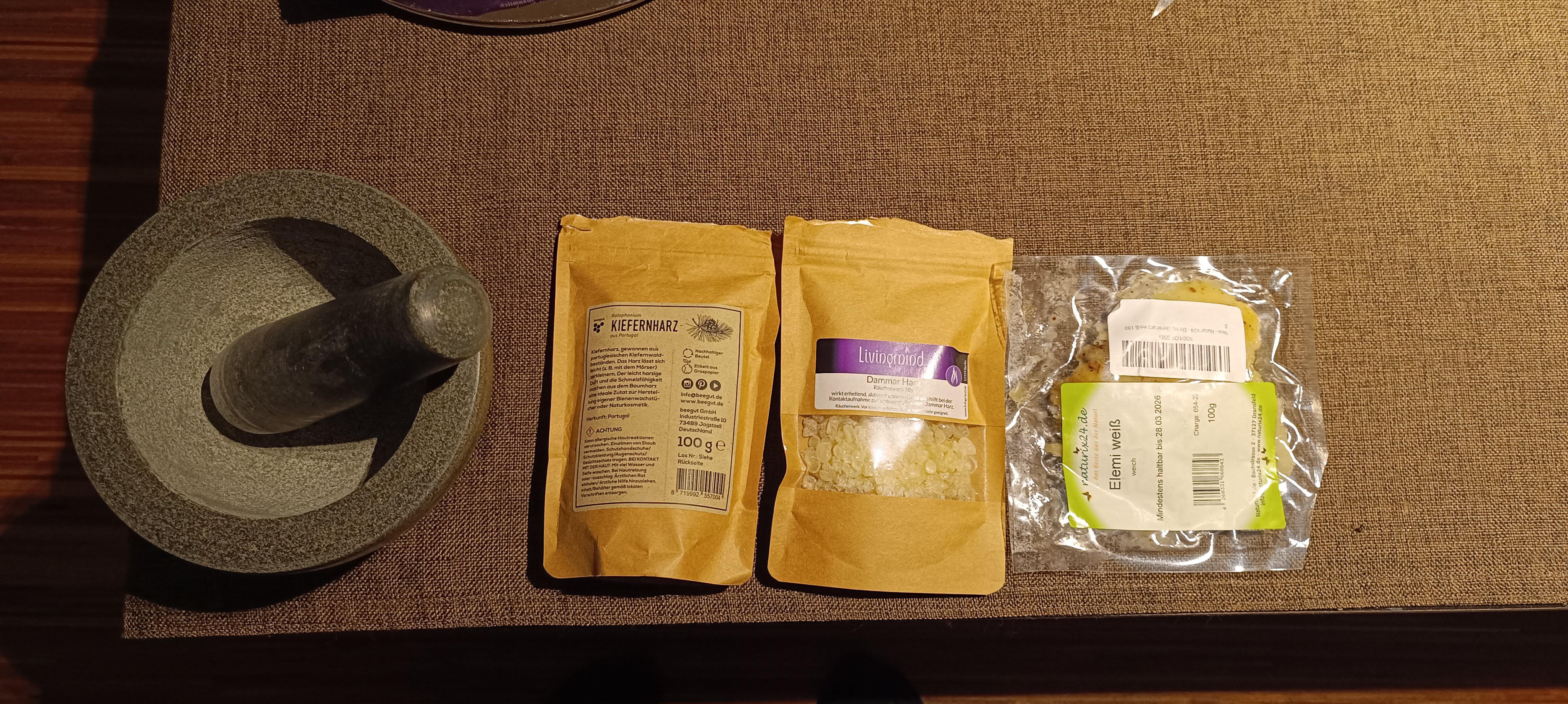
Colophonium, Gum Dammar and Elemi
Just to mention it, I also tried out gum dammar, which turned out not to dissolve in ethanol, and elemi, which dissolved, but the surface was more like wax than varnish or ink.
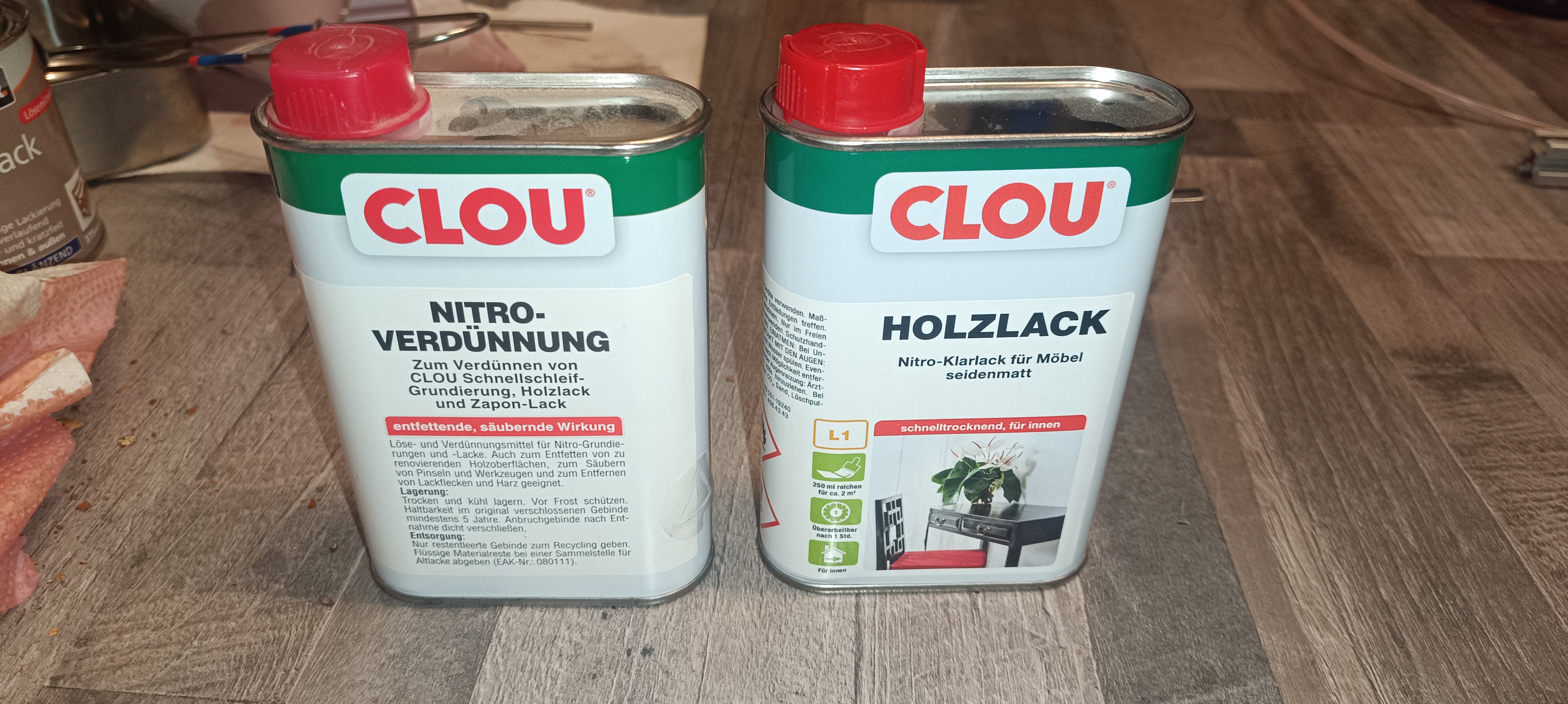
Trying out solvent-based Varnish
To leave nothing untested, I also tried out solvent-based varnish from the hardware store, which I think was important for gaining the experience, but I wouldn't recommend it or try it again, especially not in winter when opening a window brings the temperature down to frosty levels.
Nitrocellulose based Varnish
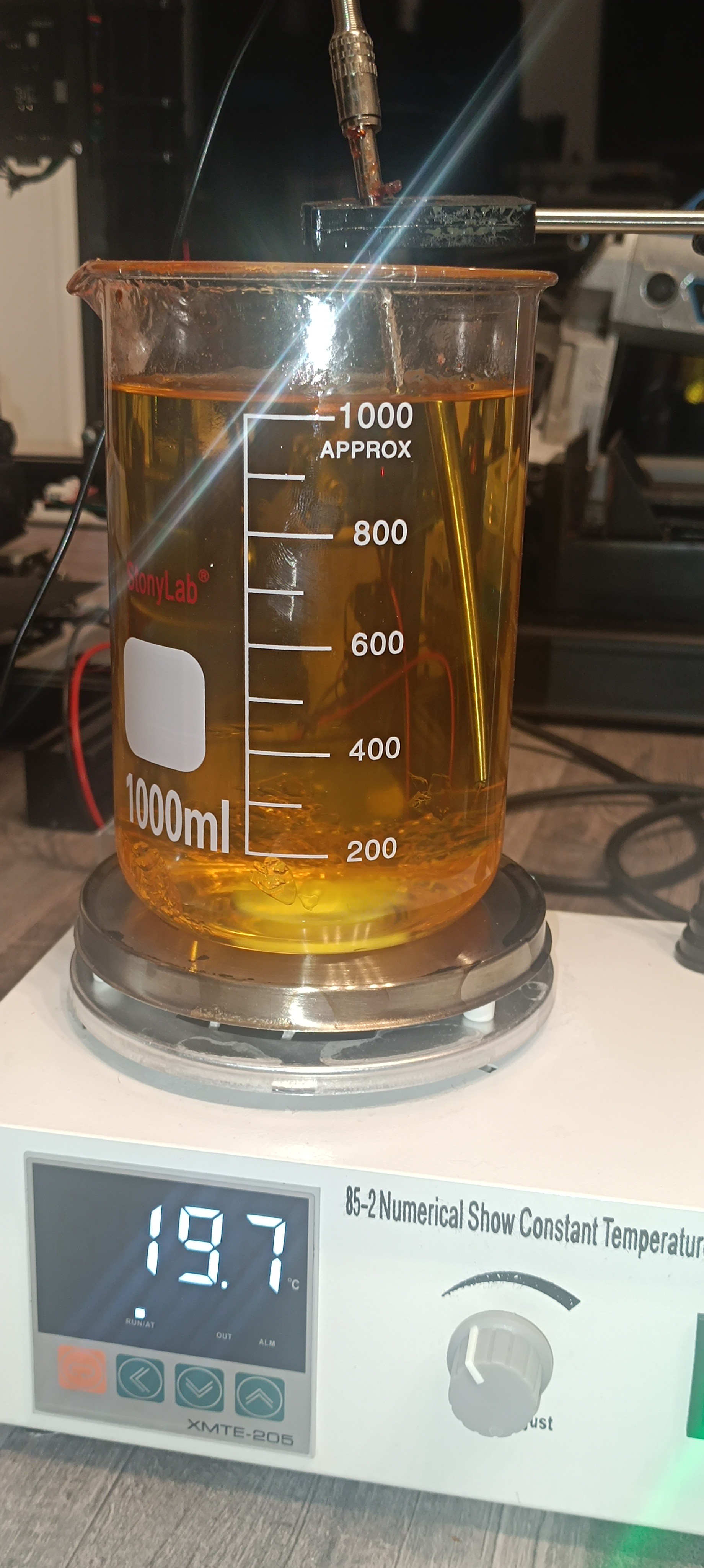
I started with mixing 1l nitrocellulose-based varnish and checking how the mixture ratio influenced its viscosity.
It turned out as expected - the varnish-to-solvent ratio influenced its viscosity.
After working for some time with it, the smell got so horrible that I decided not to continue testing with it, since I'm planning to use the printer inside the same space where I live, like any other 3D or desktop printer.
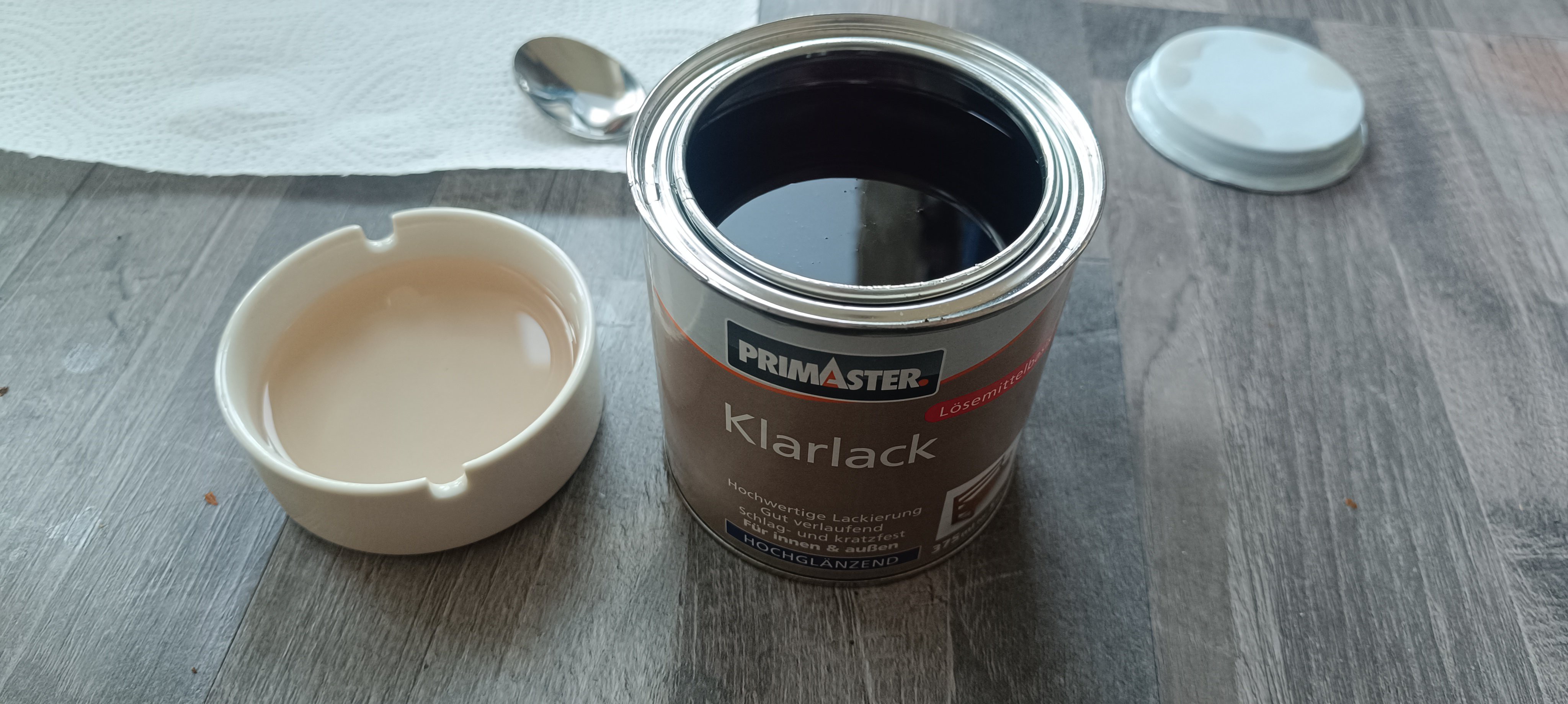
The next thing I tried was using alkyd resin-based varnish, which I mixed with white spirit "Reinigungsbenzin".
Alkyd-based Varnish
Varnish dissolved in White Spirit "Reinigungsbenzin"
It turned out that the alkyd resin-based varnish from the hardware store dissolved well in white spirit "Reinigungsbenzin".
While the varnish and white spirit also had an unpleasant smell to it, it was by far not as bad as the smell from nitrocellulose-based varnish.
So, I prepared 2l of it, checked its viscosity, and loaded it into the printer after draining the shellac from it and flushing it with pure ethanol.
This turned out to be not the smartest idea I ever had since, after loading around half a liter of it, the peristaltic pump suddenly stalled, which made me realize that the white spirit caused the silicone tube to expand.
After thinking for a while about replacing the peristaltic pump and silicon tube with something else to continue testing with the white spirit based ink, I reconsidered my decision and started working on a way of getting the varnish out of the printer again.
Normally, the peristaltic pump is used for loading and unloading ink into the printer, but with it being not functional, I had to find another way.
So, I used a gear pump to draw the white spirit varnish out of the printer and started flushing all lines with multiple liters of ethanol.
Gear Pump for Repair Work
Fortunately, flushing the silicone tube with ethanol reversed the expansion of the tubes, and the peristaltic pump was operational again, which made the flushing much easier.
After flushing the printer I realized that the not ethanol soluble parts of the alkyd resin varnish had formed some sort of sticky sludge inside some of the lines.
After some more flushing and cleaning of the viscosimeter pipe and steel ball to get it functional again, most of this sludge settled inside the bottom and filter of the ink tank.
Sludge on the Bottom of the Filter Housing
So, I cleaned the tank and ordered some new filters. Since I was already working on the tank, I decided to improve the design by using 10-micron string-wrapped filters and changing the placement of the inlets so that the return line and the solvent line get filtered as well.
This should prevent particles larger than 10 microns from entering the 100-micron nozzle.
Cleaned Filter Housing
Filter Housing with 10 Micron String Wrapped FilterInlets moved to the Outside of the Filter
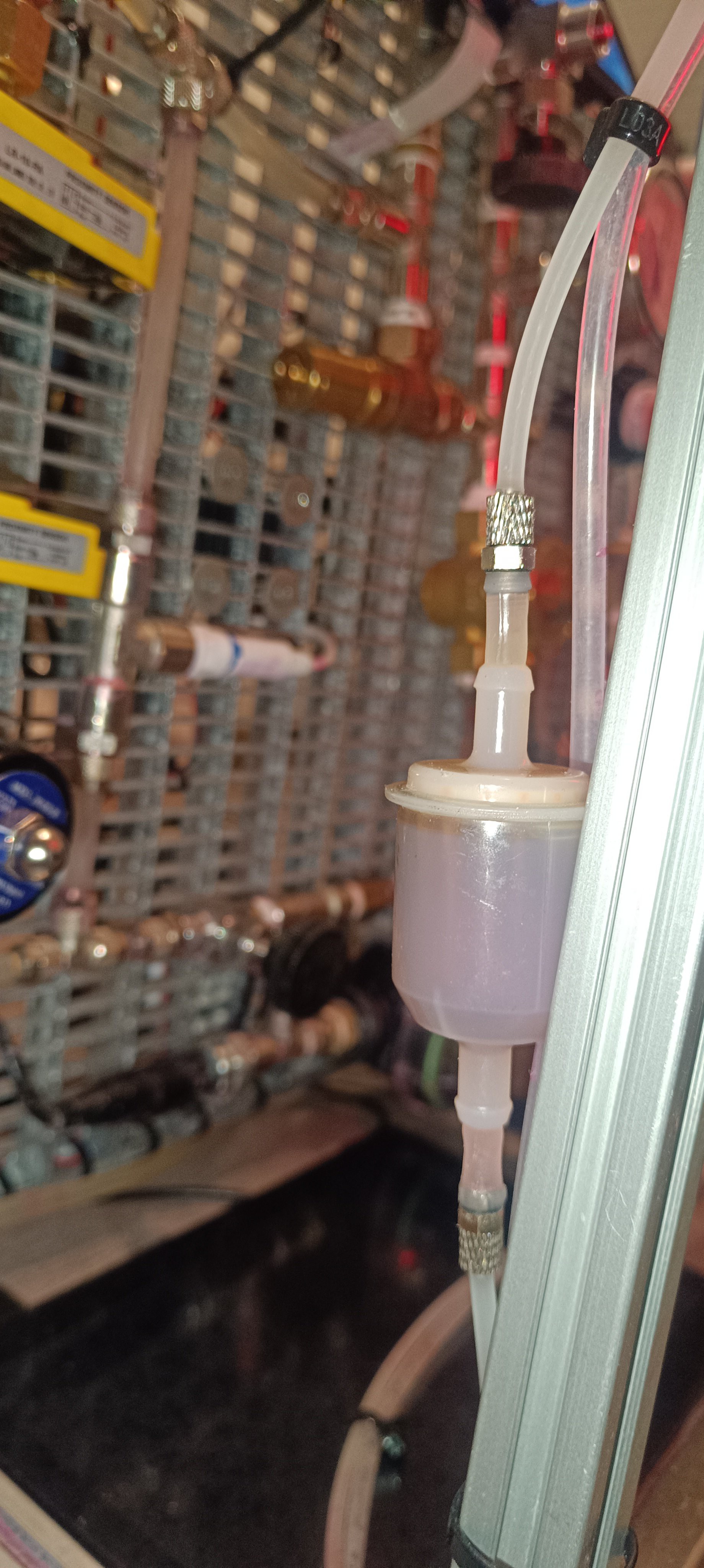
To add even more clog protection to the nozzle, I placed a fuel filter close to the printhead.
My initial plan was to not use a filter inside the ink line going to the printhead and keep it clean by applying a vacuum to this line for reverse flushing the nozzle with ethanol to get all large particles out. Unfortunately, this didn't work well, and the nozzle got constantly clogged, which required unscrewing and cleaning the nozzle before every test.
It later turned out that adding the filter as close as possible to the nozzle was a real game changer because after adding it and thoroughly flushing out all particles by starting with a 0.3mm nozzle first, then a 0.2mm nozzle, and finally the 0.1mm nozzle, the nozzle never got clogged again.
With the filter added it still was possible to reverse flush the nozzle with ethanol after printing to prevent the nozzle from getting clogged by hardened ink.
Fuel Filter close to the Printhead
Gum Sandarac
After testing the alkyd resin varnish and deciding against it because of the incompatibility with the silicone tube and also because I was worried about getting health issues from long-time exposure (the printer prototype is standing in my living room), I continued searching for ethanol-based varnishes and found gum sandarac based varnish.
So, I ordered a bag of it for testing.
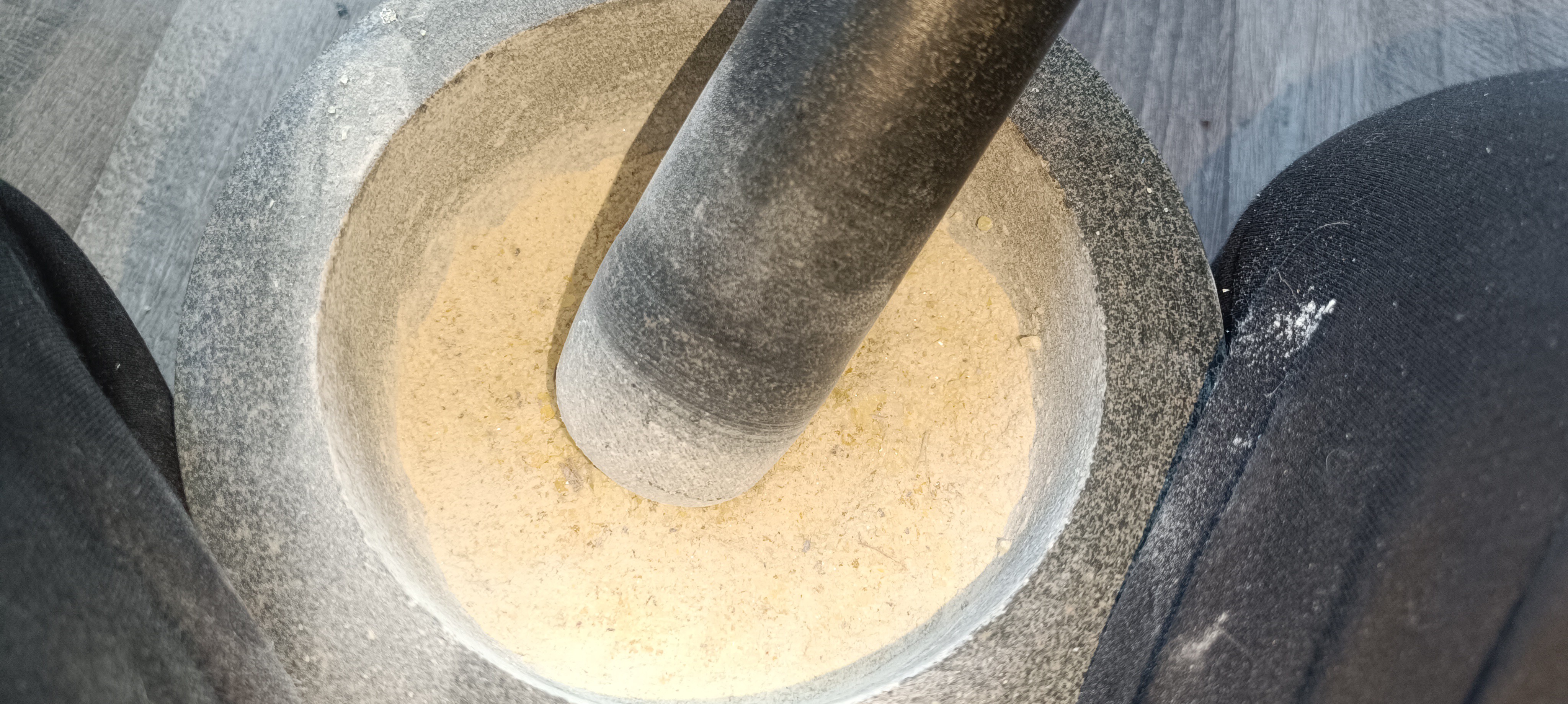
Bag of Gum SandaracSandarac is a tree resin that gets shipped in small chunks which need to be ground down before mixing.
Chunks of Sandarac Resin
When grinding it down to a powder, I noticed the nice smell of the resin, which is an advantage.
Ground Sandarac Powder
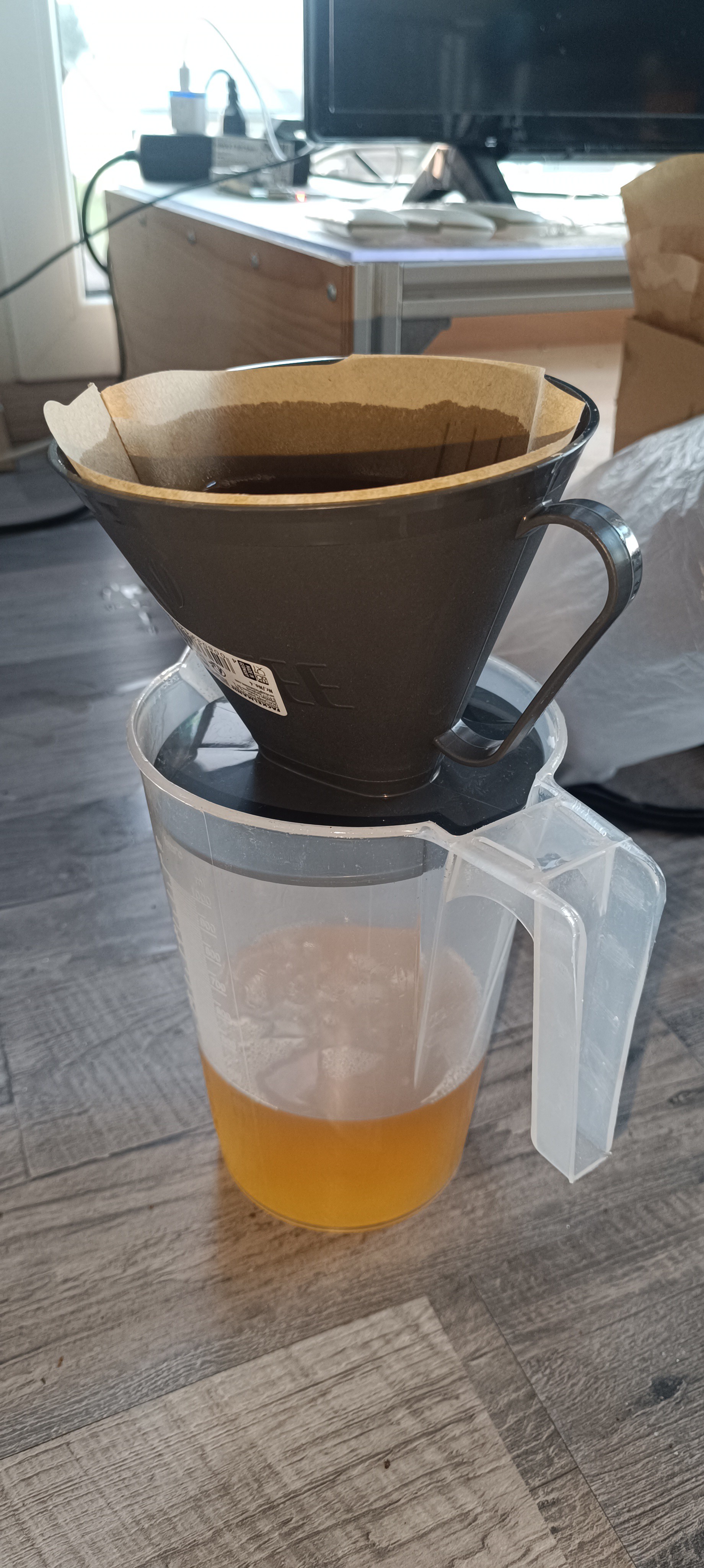
While mixing it with ethanol, I noticed that it contains a lot of dirt, small sticks, and stones, which makes it necessary to filter it thoroughly.
So, I used a bunch of coffee filters to filter out all the dirt.
Filtering out the Dirt
Filtering by using Coffee Filters
With all dirt filtered out the mixture had a clear yellow color.
Clean Mixture of Sandarac Ink
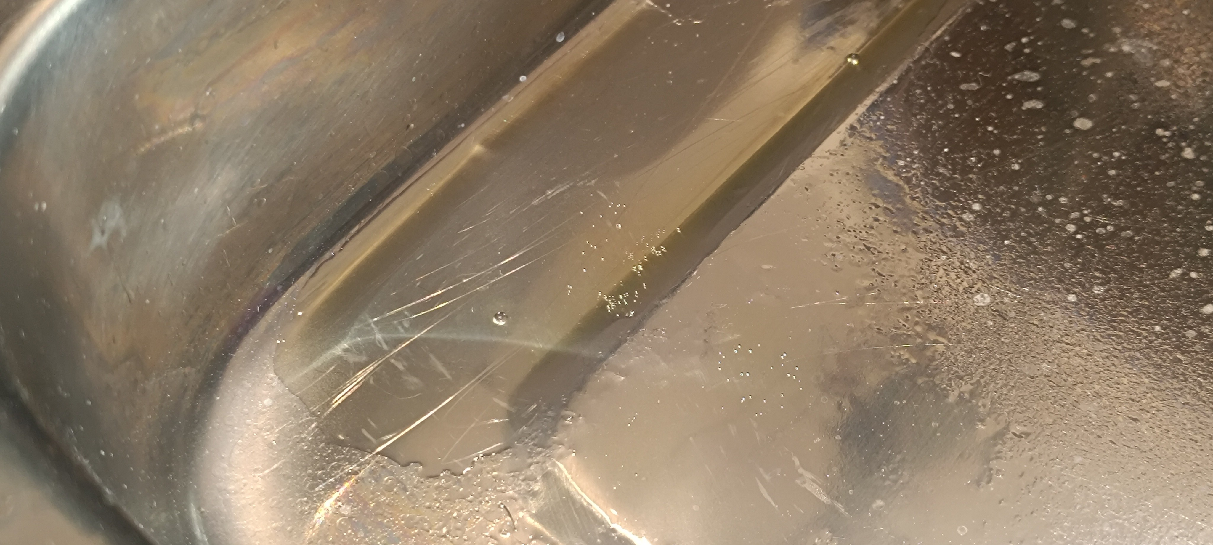
After filtering the ink, it was time to pour some of it into the drip tray and let it dry.
When the ink had completely dried, it formed a nice shiny, clear, and nonsticky surface with good adhesion. The dried ink was so shiny that it wasn't even possible to tell from just the look of it if it was dry or still liquid.
Dried Sandarac Ink
The test turned out very positive, and the ink was ready to be loaded into the printer. So, I connected a silicone tube to the gutter and loaded the ink into the printer via the return line.
Loading the Ink via the Return Line
Another Cup of Ink with a higher Concentration
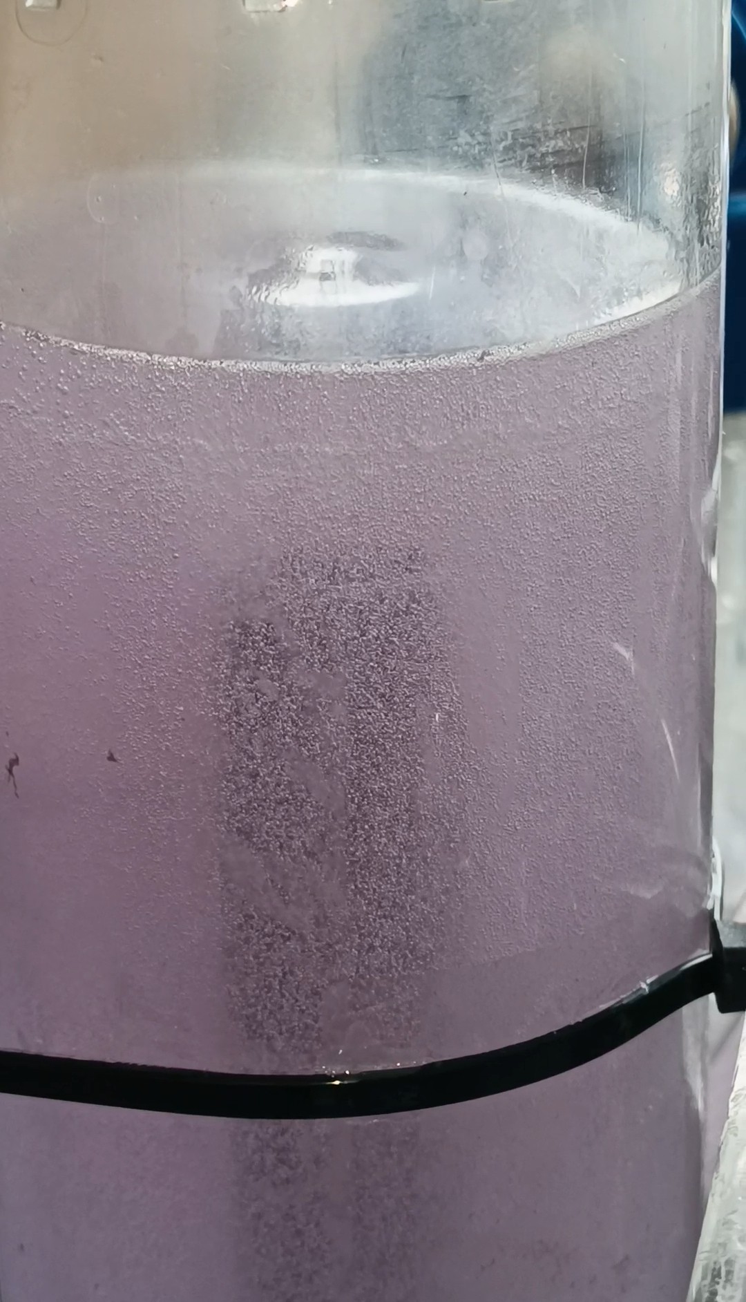
Look at the Sandarac Ink inside the Printer Tank
With the sandarac ink loaded into the printer, I powered the printer up, started the circulation pump, and heated the ink inside the printer to 25⁰C before checking the viscosimeter. It seems like the sandarac doesn't increase the viscosity of the ink as much as the other resins I tried so far did, but even with a lower viscosity, the ink formed a nice surface.
The sandarac ink's viscosity was around that of spray paint, and I think this lower viscosity would be even more suitable for printing because the higher viscosity of the PVB ink would have required a higher pressure for the same jet velocity and a higher power setting for the return pump to draw it through the return line.
So, I will keep it at this lower viscosity - at least for now.
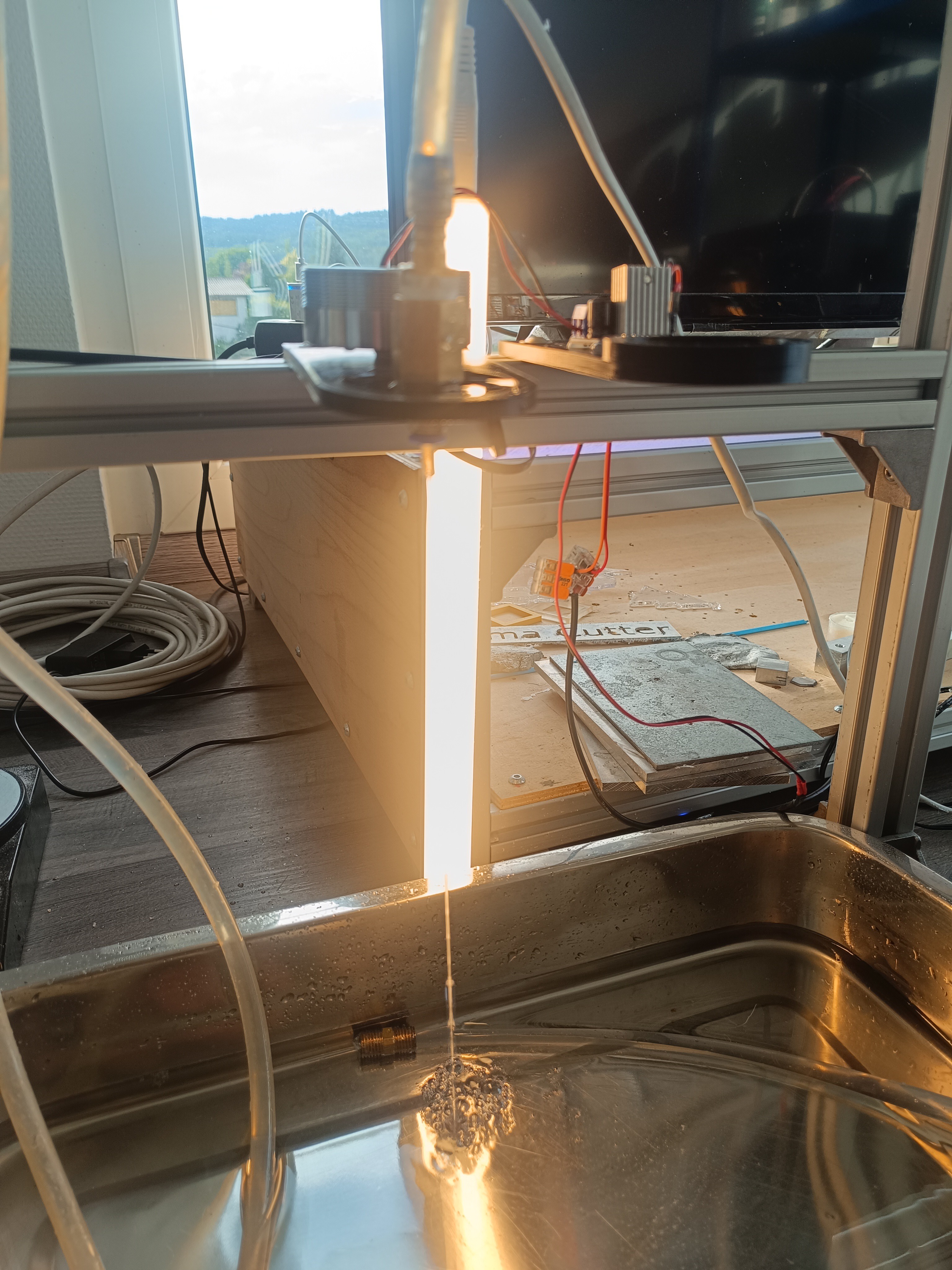
After testing the viscosity, I started the return pump, pressure pump, and ink stream.
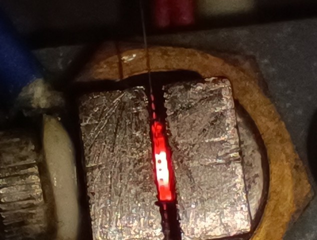
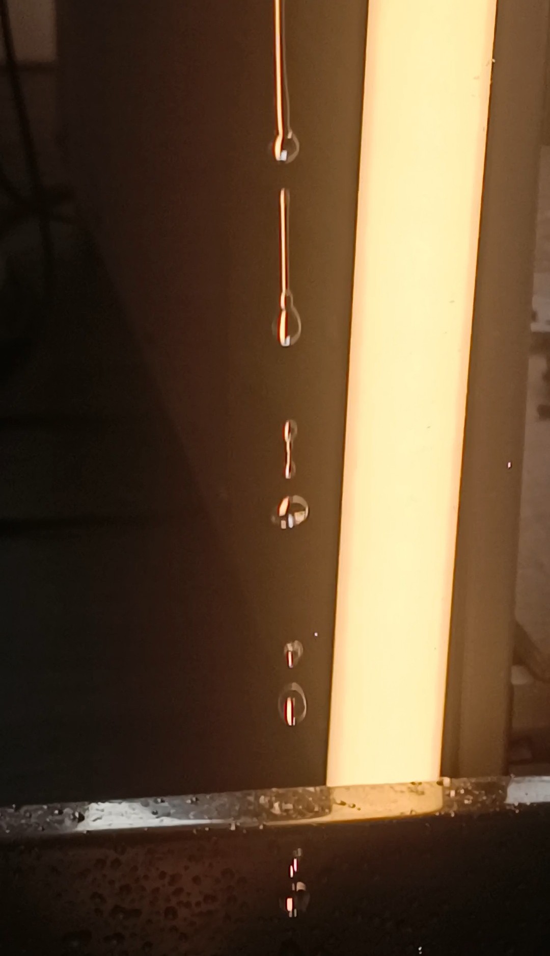
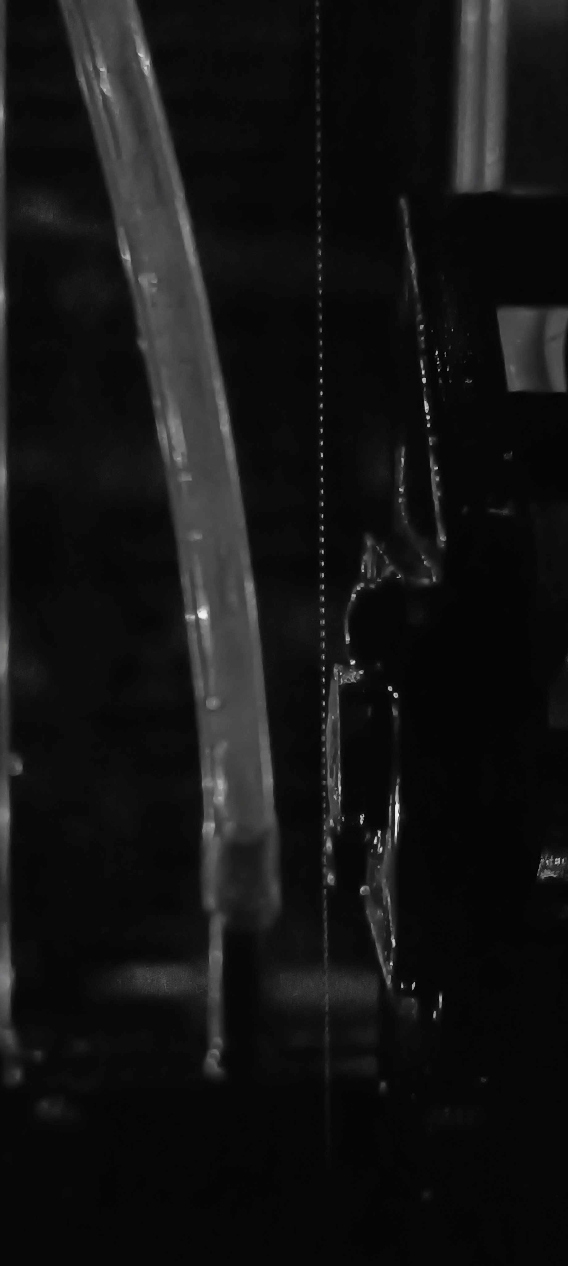
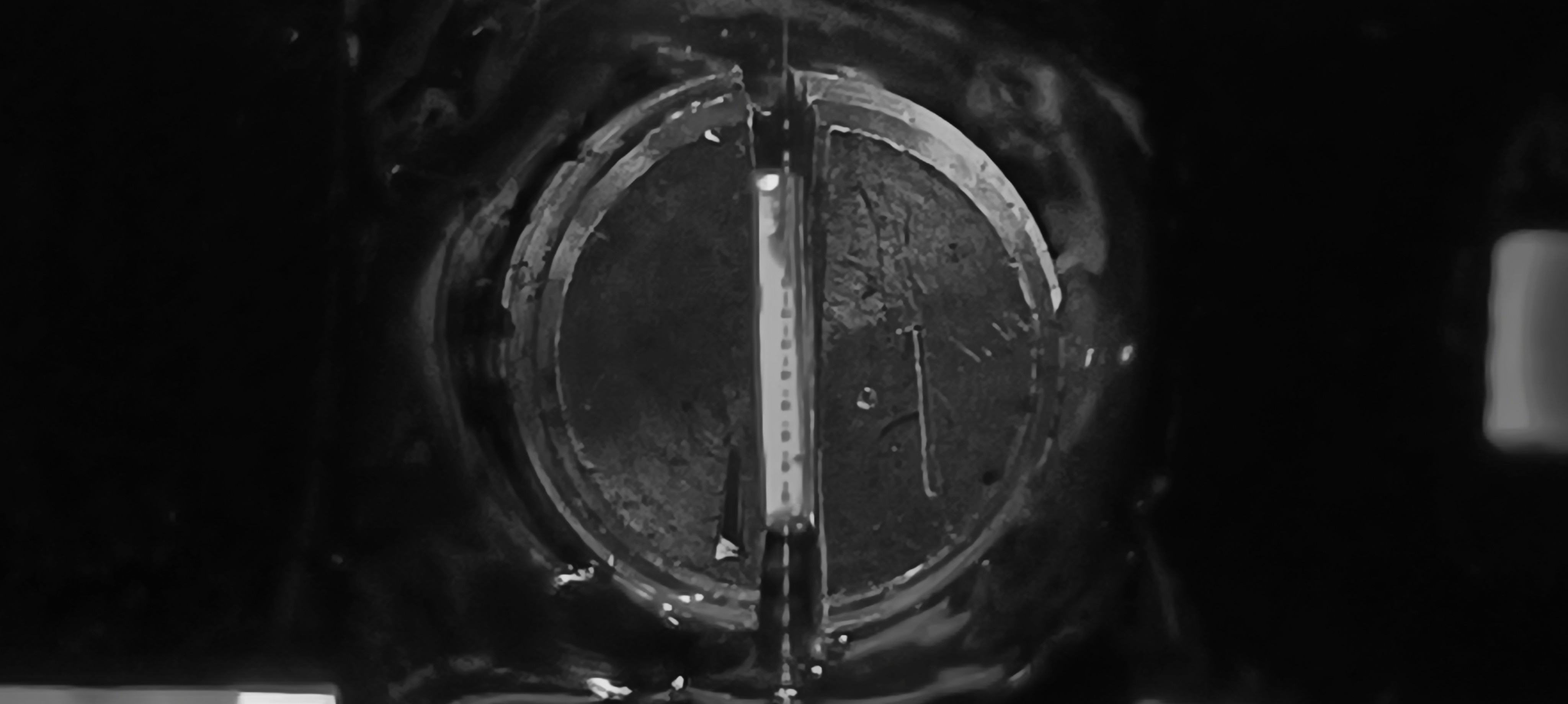
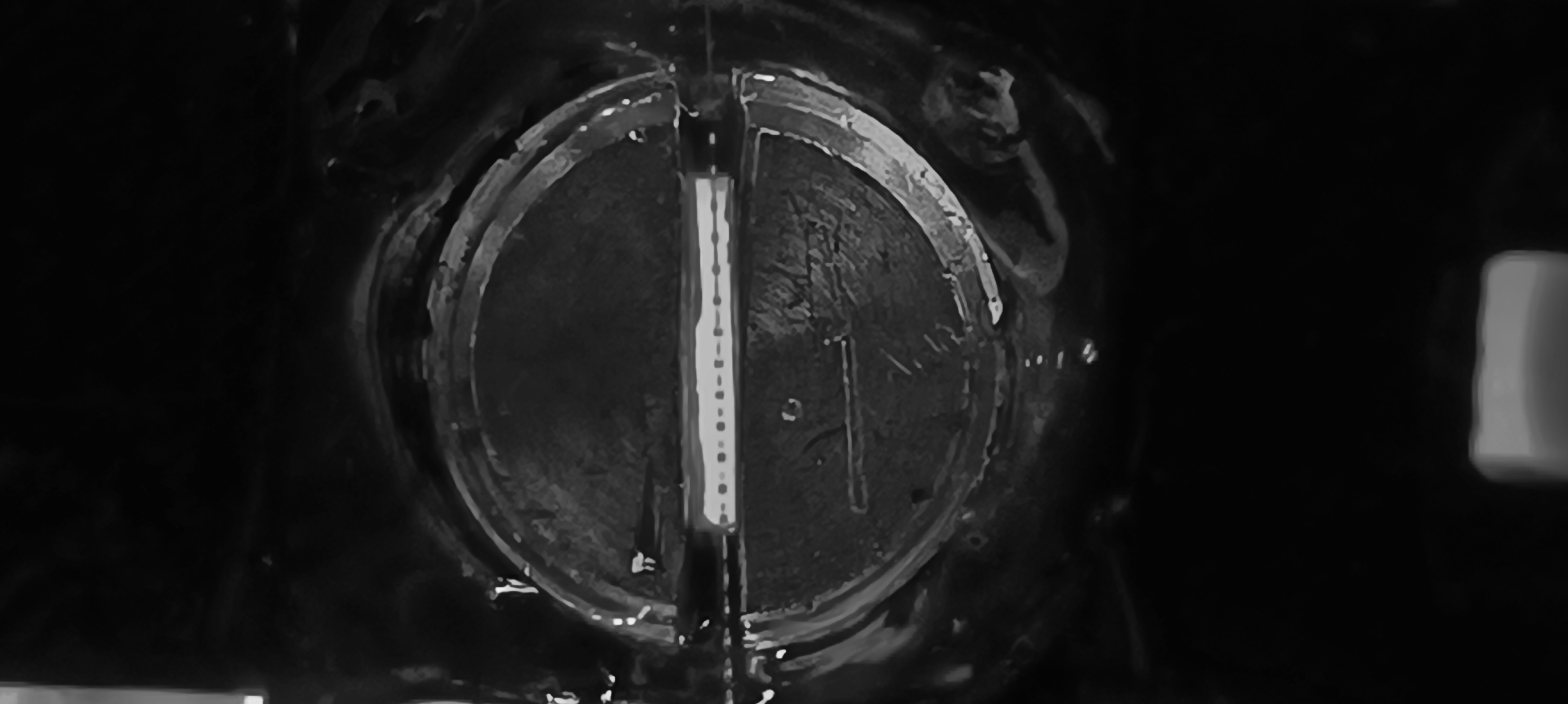
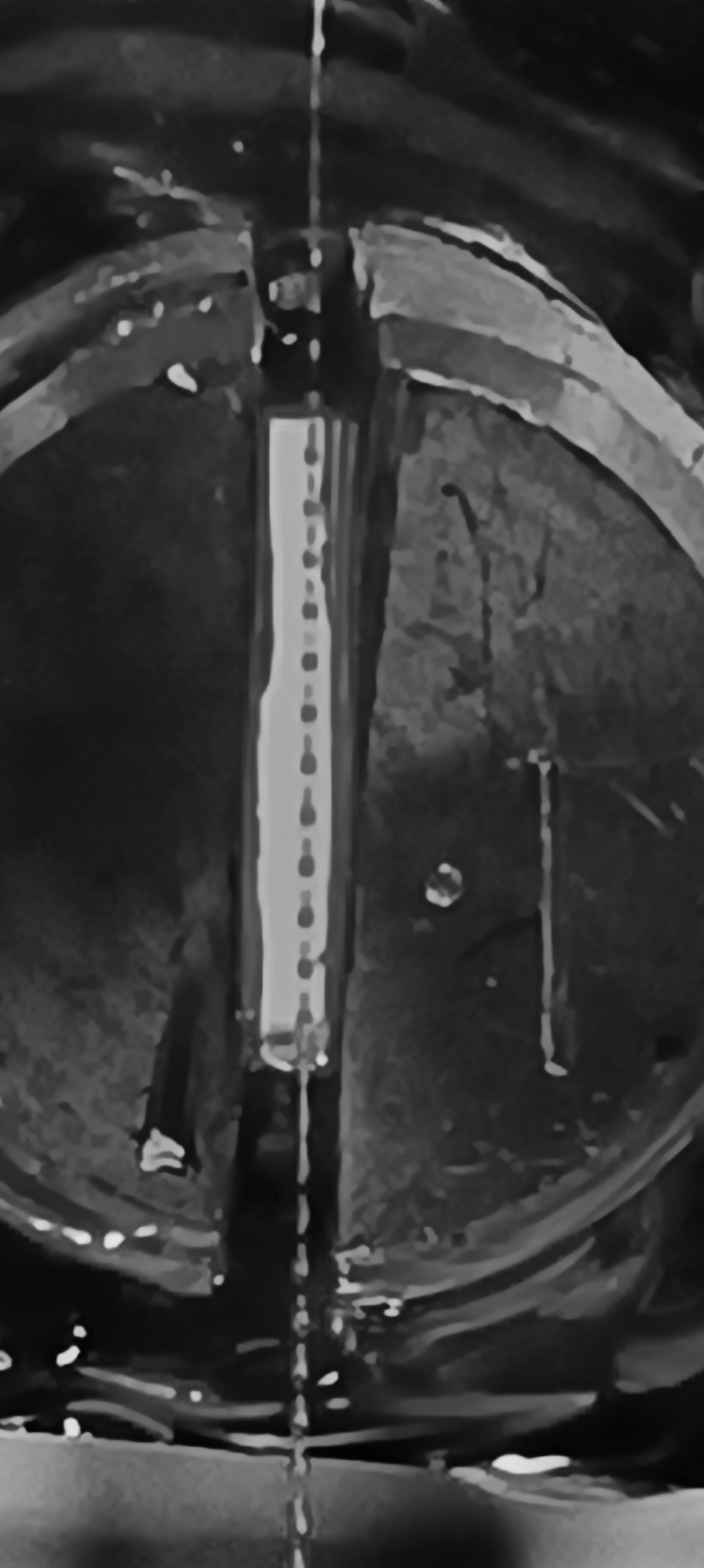
When the jet had formed I took a few black and white photos of it:
More photos with different pressure settings:
,
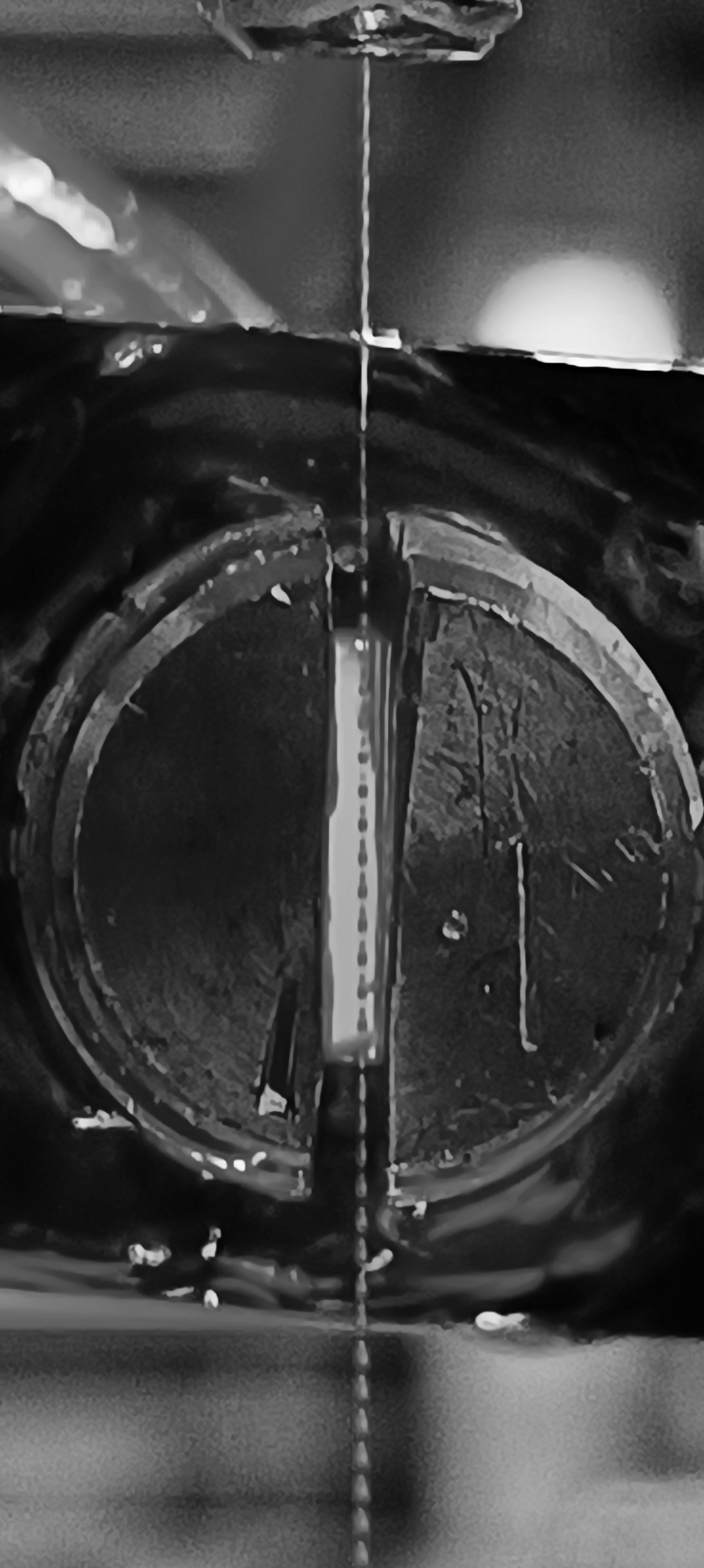
Depending on the pressure, the jet velocity changed and, with it, the position of the breakup point and also if there were satellite droplets.
Changing the piezo drive amplitude also changed the breakup point's position and satellite droplets.
Frequency and piezo drive amplitude will later have a fixed setting while the pressure will be regulated for keeping the jet velocity constant.
The test and feedback signal did also work well with the sandarac ink.
Test and Feedback Signal
Conclusion
I think testing different ink mixtures gave me some insights into the topic and led to some nice improvements that made the design more reliable.
When ranking the tested ink mixtures I would put sandarac at the first place and shellac on the second place.
Alkyd resin based ink and nitrocellulose based resin could be used, but I wouldn't recommend it and it would require changing out some parts of the printer like the silicone tube and plastic parts that would be dissolved by the more agressive solvent.
For now, I will continue using the sandarac ink since it's plant-based, not poisonous, forms a nice surface, works well with the CIJ process, and smells nice.
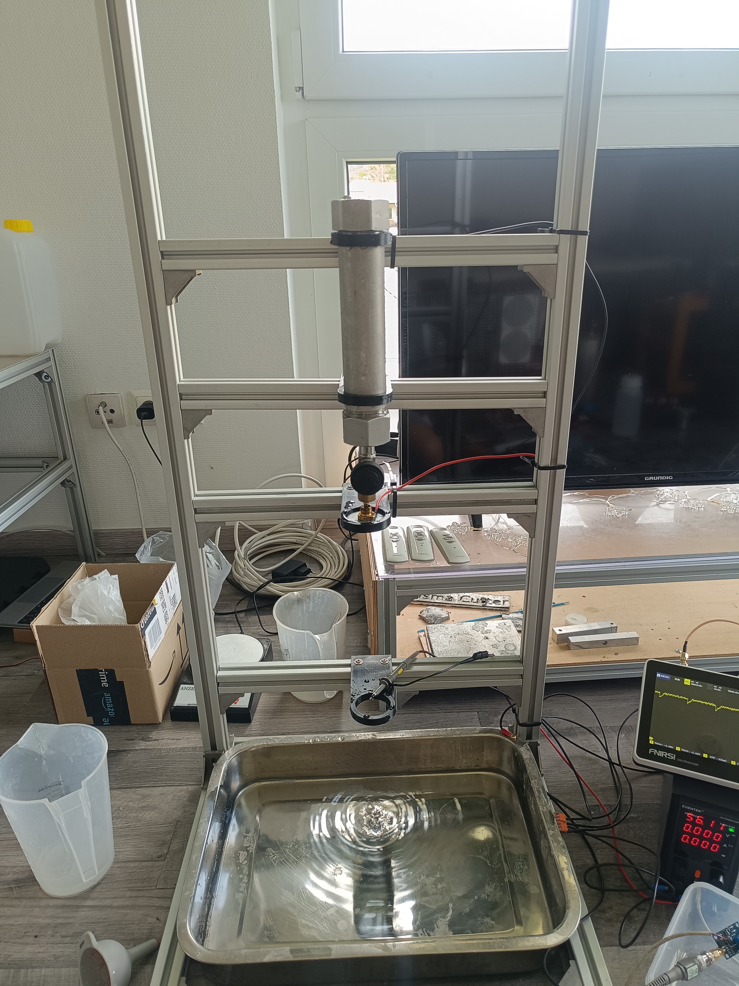
My next goal is to measure the speed of the ink stream by using two sensors and counting the time the droplets need to travel from sensor to sensor.
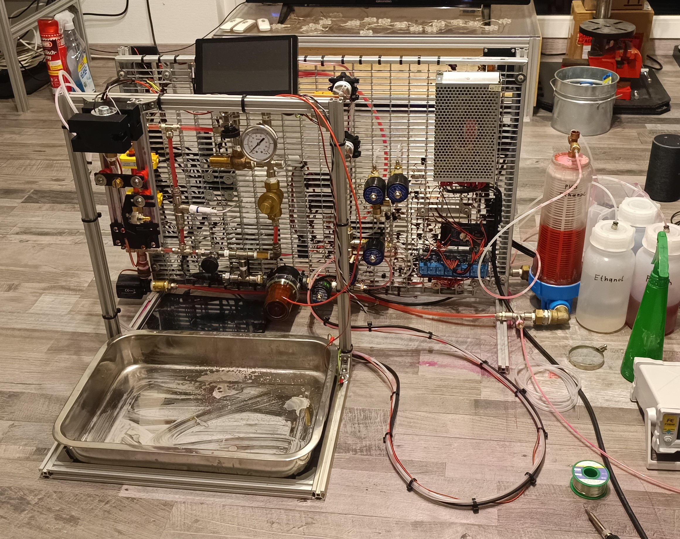
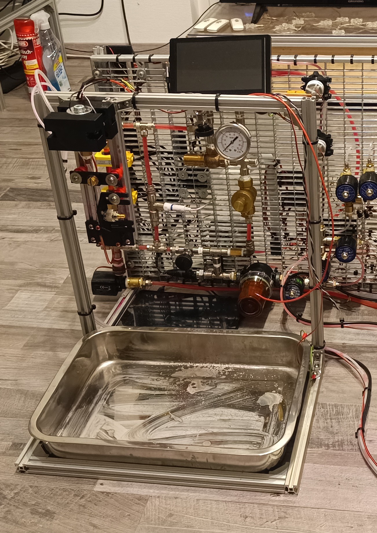
To make work on the electronics easier, I built a new printhead test stand with a drip tray for catching ink drops that miss the gutter.
Current Look of the PrinterPrinthead mounted on the Test Stand
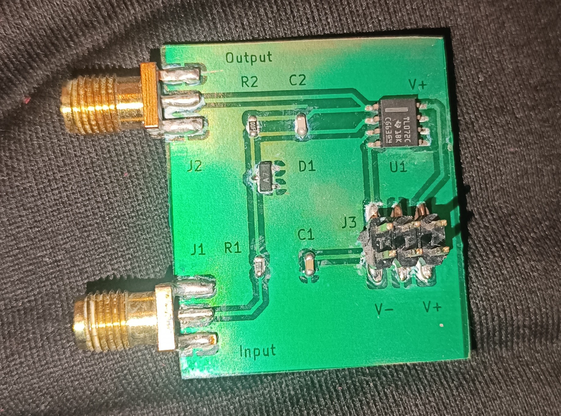
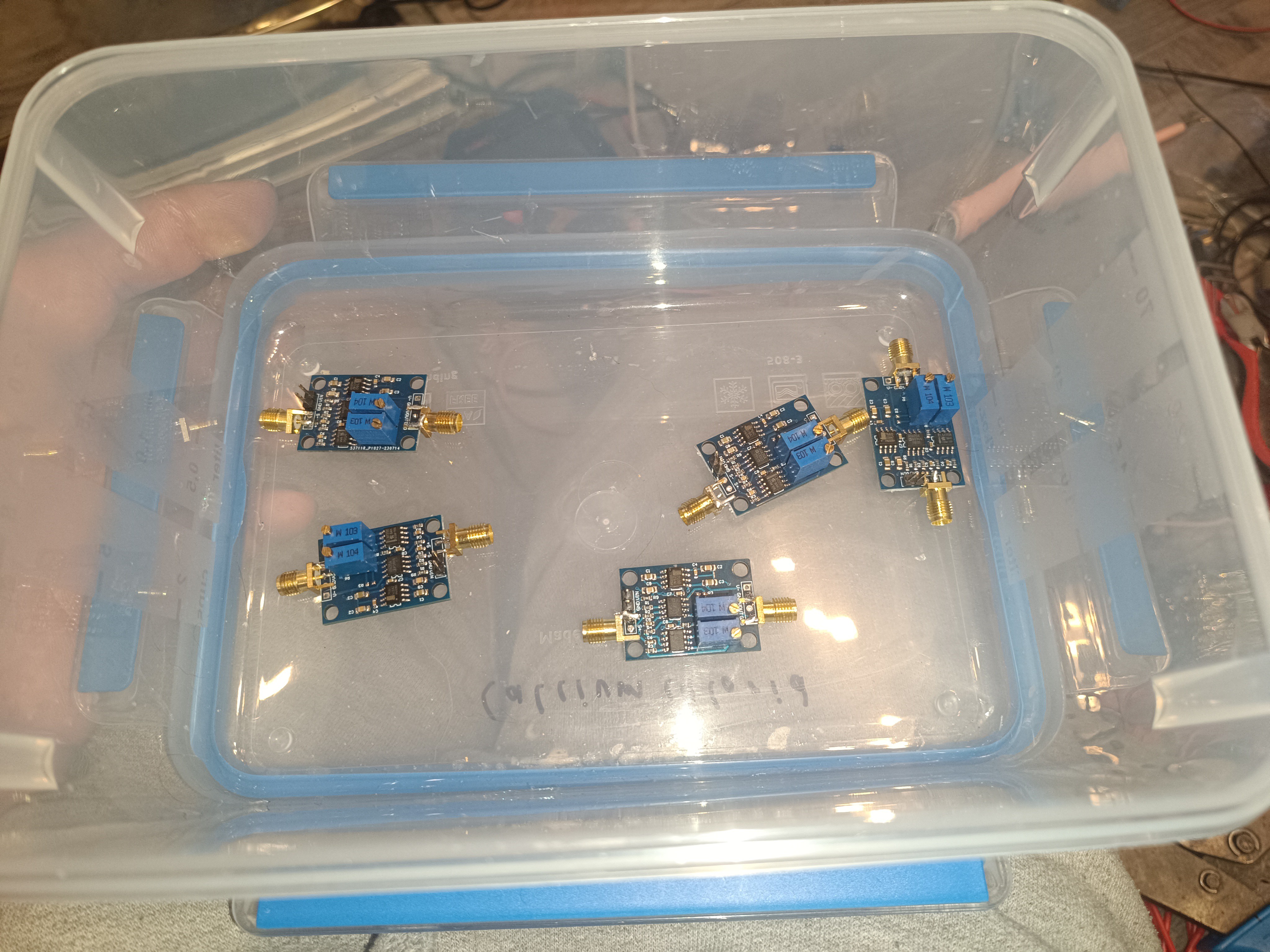
After everything was in place, I tried building an amplifier for measuring the small charge that would be applied to the droplets by a Time-of-flight test signal.
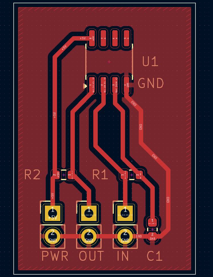
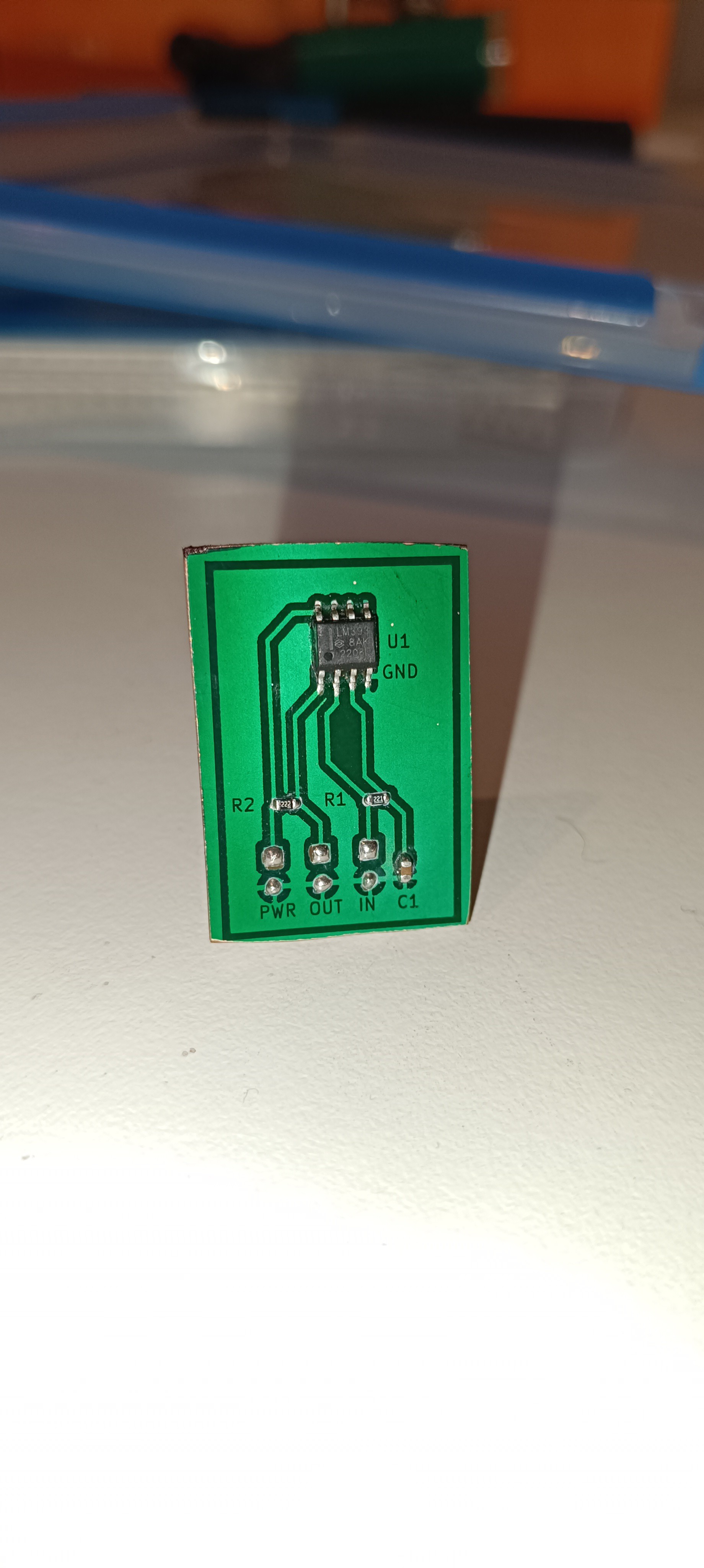
The Amplifier's Schematic
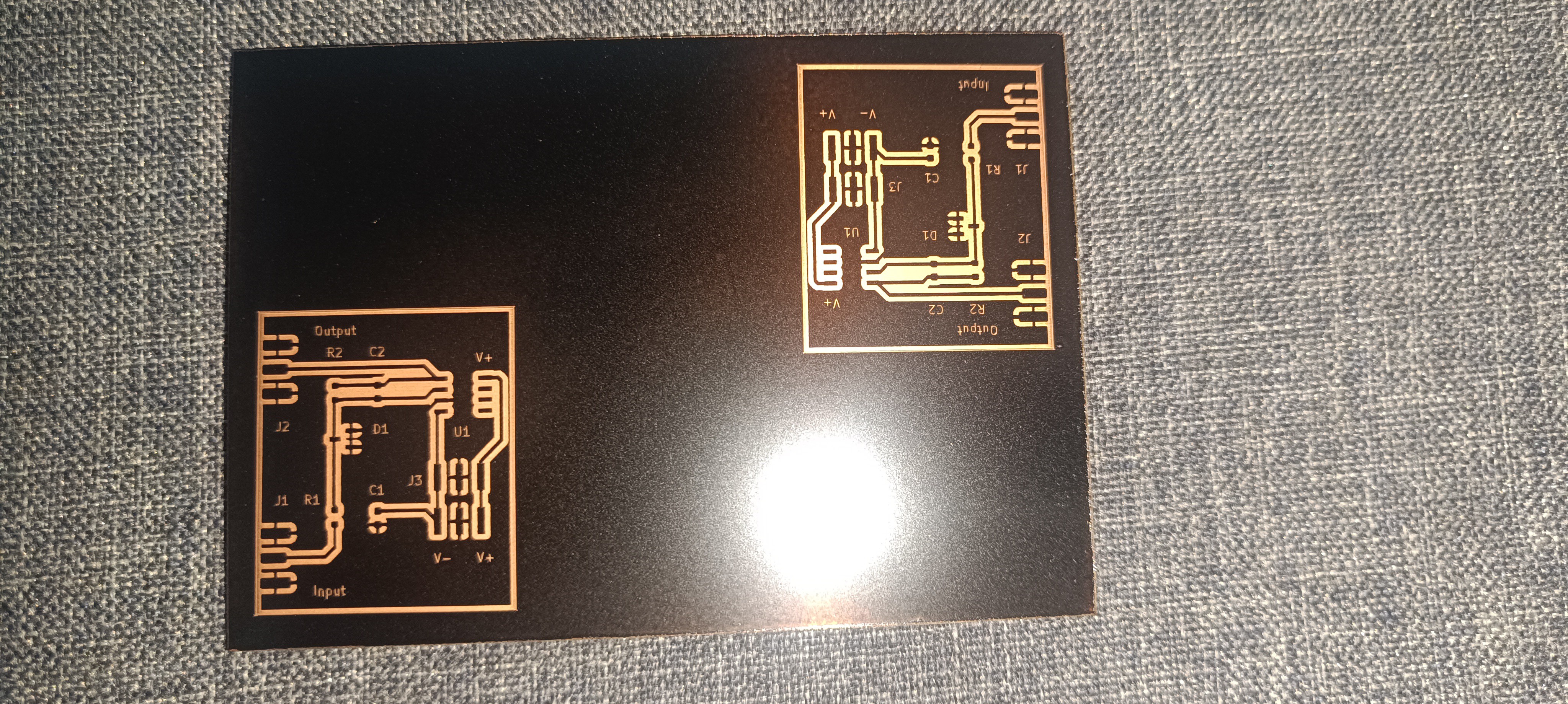
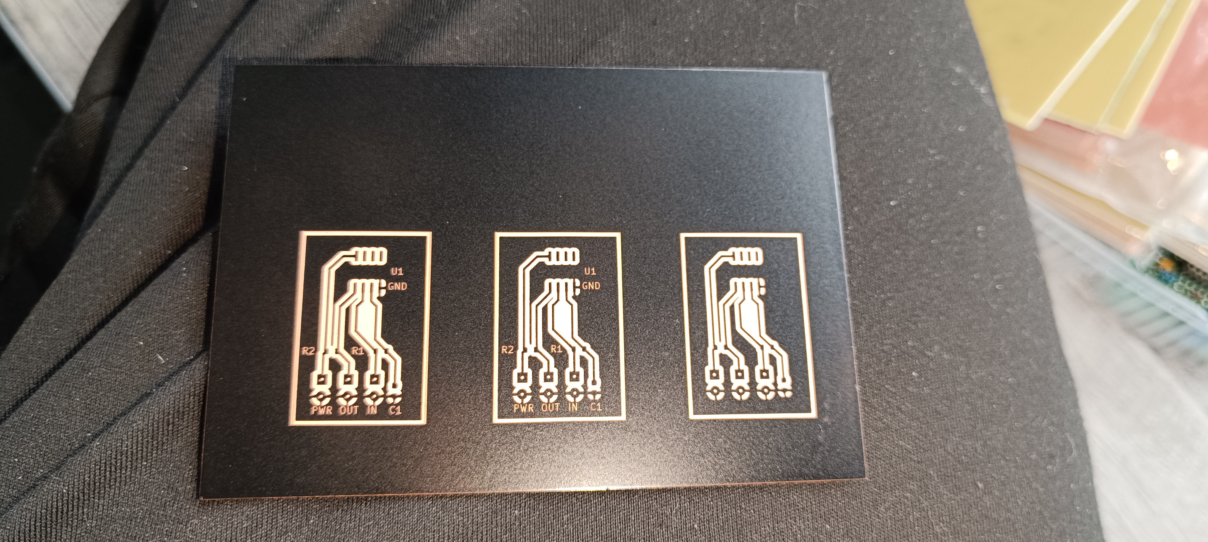
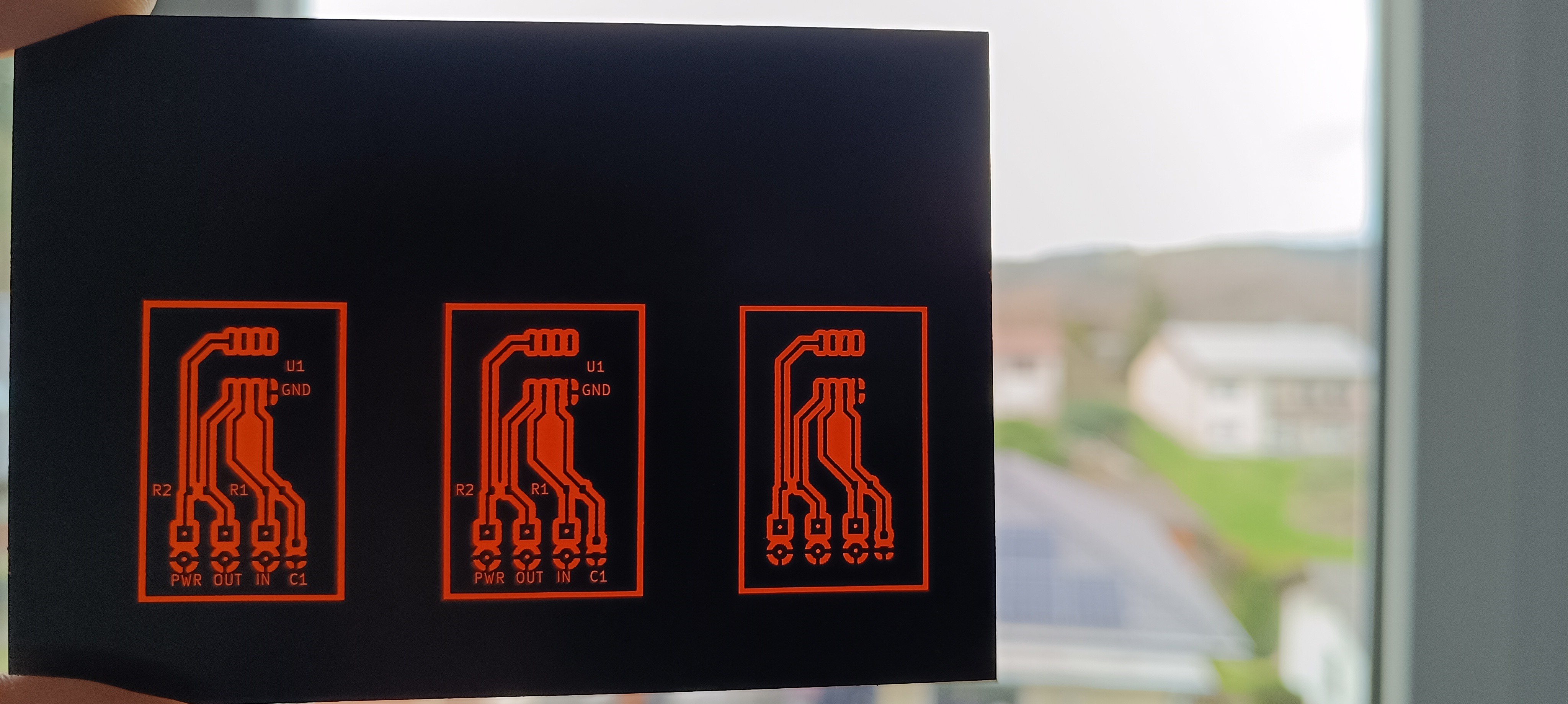
Lasered PCB
PCB after EtchingCleaned up PCB
PCB with Solder MaskFinished Amplifier
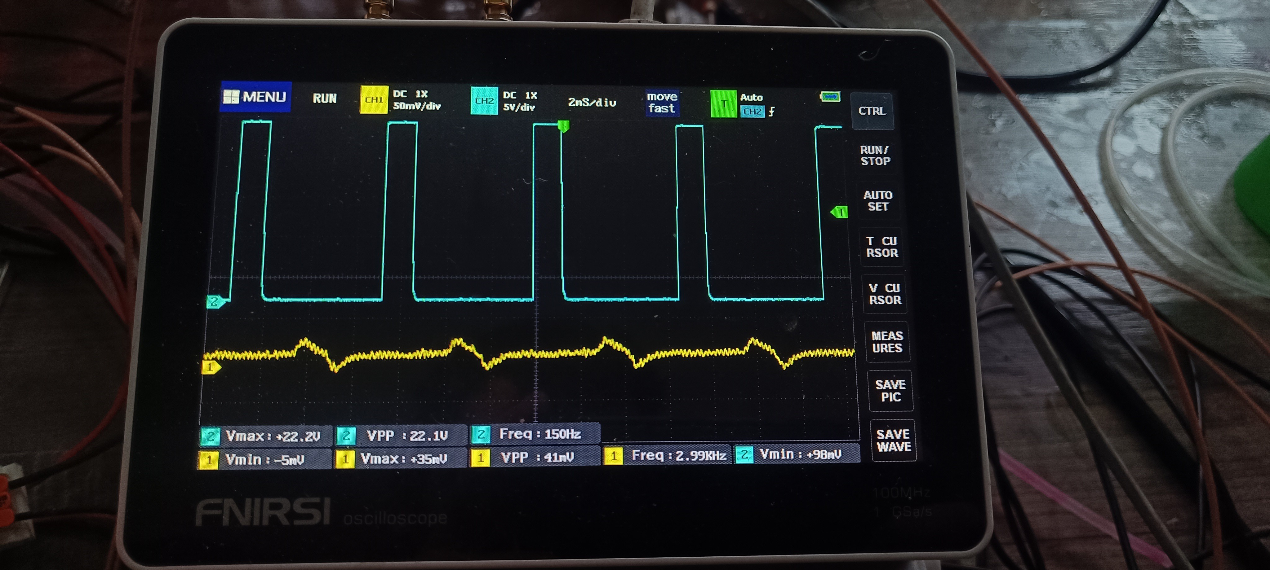
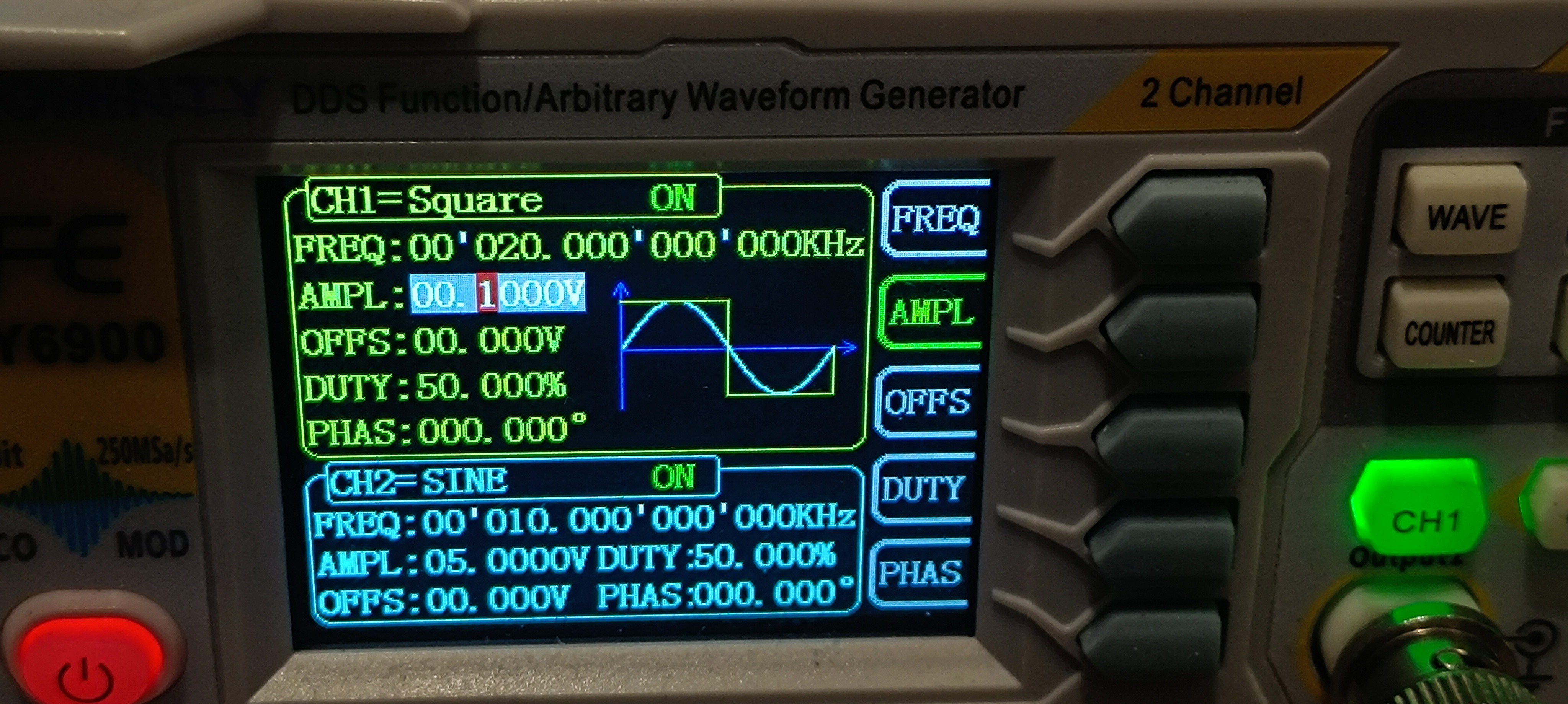
To verify that the amplifier works, I did a quick test of the new amplifier by applying a 0.1V 20kHz signal and looking at the amplifier's output.
Signal Generator with Test SignalOutput of the Amplifier
The test showed that the amplifier is turning the sent 0.1V square wave signal into a 0.25V triangle wave.
While I didn't expect the output signal to be a triangle wave and I also thought that the amplification would be a bit higher, the test showed that the built circuit was working.
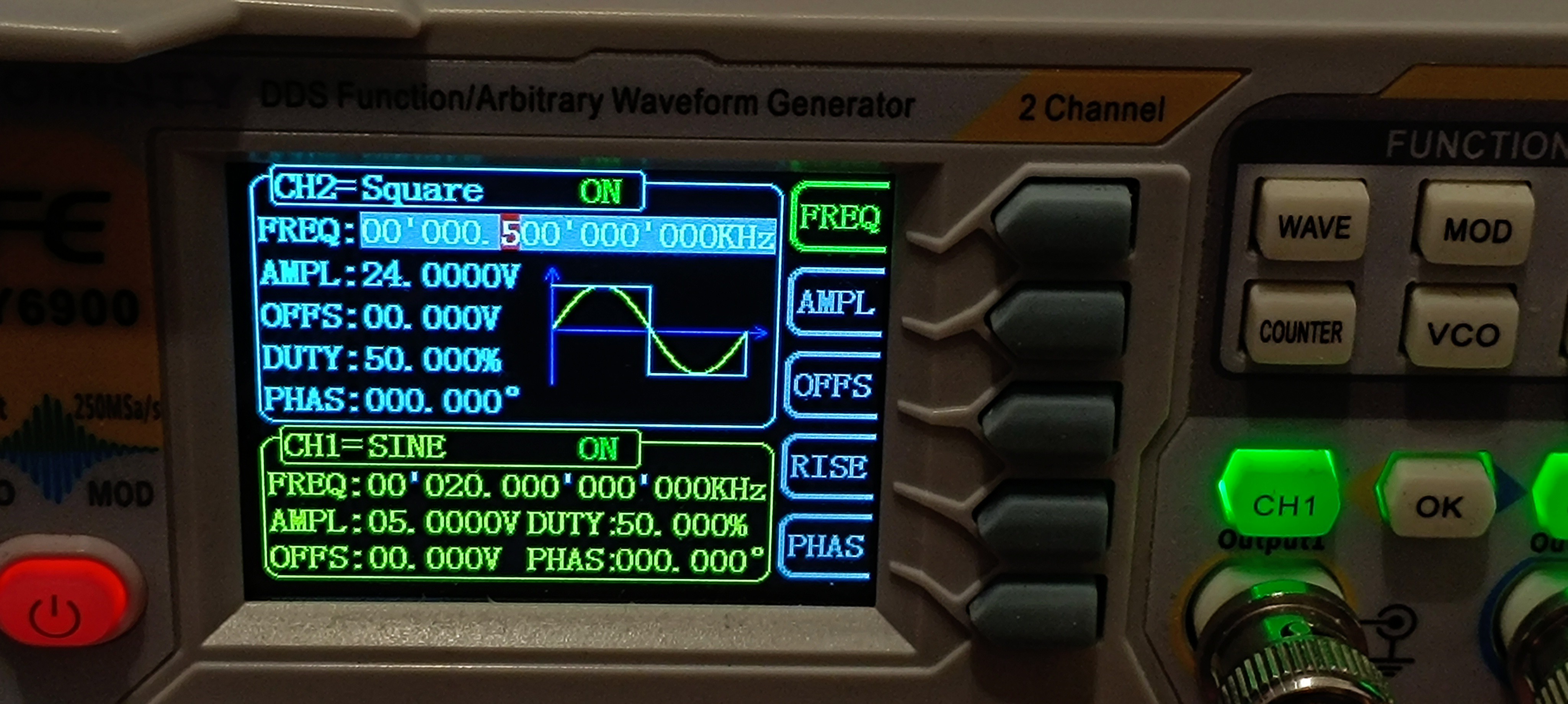
So, I built a sensor out of a UHF connector that I connected to the amplifier for detecting the charge on the droplets and applied a test signal to the charge electrode.
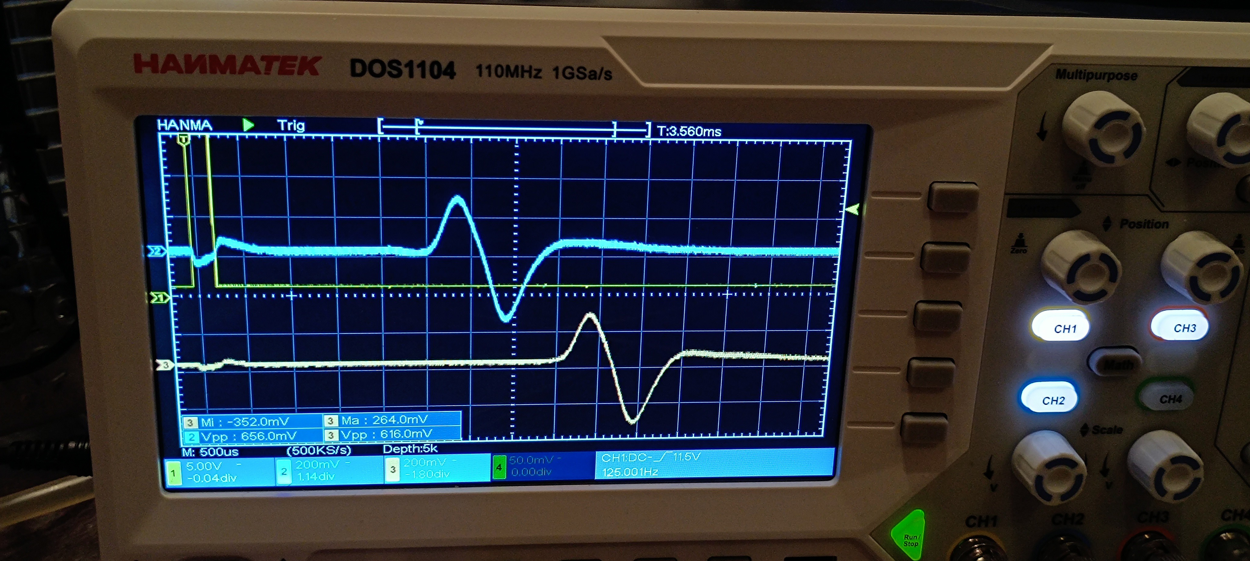
UHF Connector as Sensor24V 500Hz Square Wave sent to the Charge ElectrodeFeedback Signal from the Amplifier
Conclusion after the first Test:
For now, it looks like it's possible to send a test signal to the charge electrode and receive a feedback signal through the amplifier.
This is an improvement compared to the AD620 amplifier that I have used so far since the old amplifier only worked randomly, and most of the time, it didn't work at all.
The new amplifier, however, is working pretty reliably so far.
Here is a short video of the test:
At the moment of writing this, I already built another one and added a TDA2030 amplifier and a high-pass filter to each one of the two to further amplify the signal and filter out the 50Hz mains frequency.
Amplified and filtered Signal of two Sensors
I also built a new sensor assembly made out of a PCB. The new one provides two sensors with a fixed distance between them so that the jet velocity can be calculated by using the known distance and the measured time delay between the signal appearing on the first sensor and the signal appearing on the second sensor.
New Sensor Assembly
The next step would be building a peak detector to get the signals ready for feeding them into a microcontroller to measure the time delay.
When that's done, it should be possible to get a stream velocity reading, which would be the first real progress on the printhead driver electronics.
After that, the same circuit could be used to test for the phase shift that works best for charging, but the current amplifier design is too slow to detect groups of charged droplets at the needed frequency.
So, a redesign of the amplifier circuit would be needed before it's ready for this test.
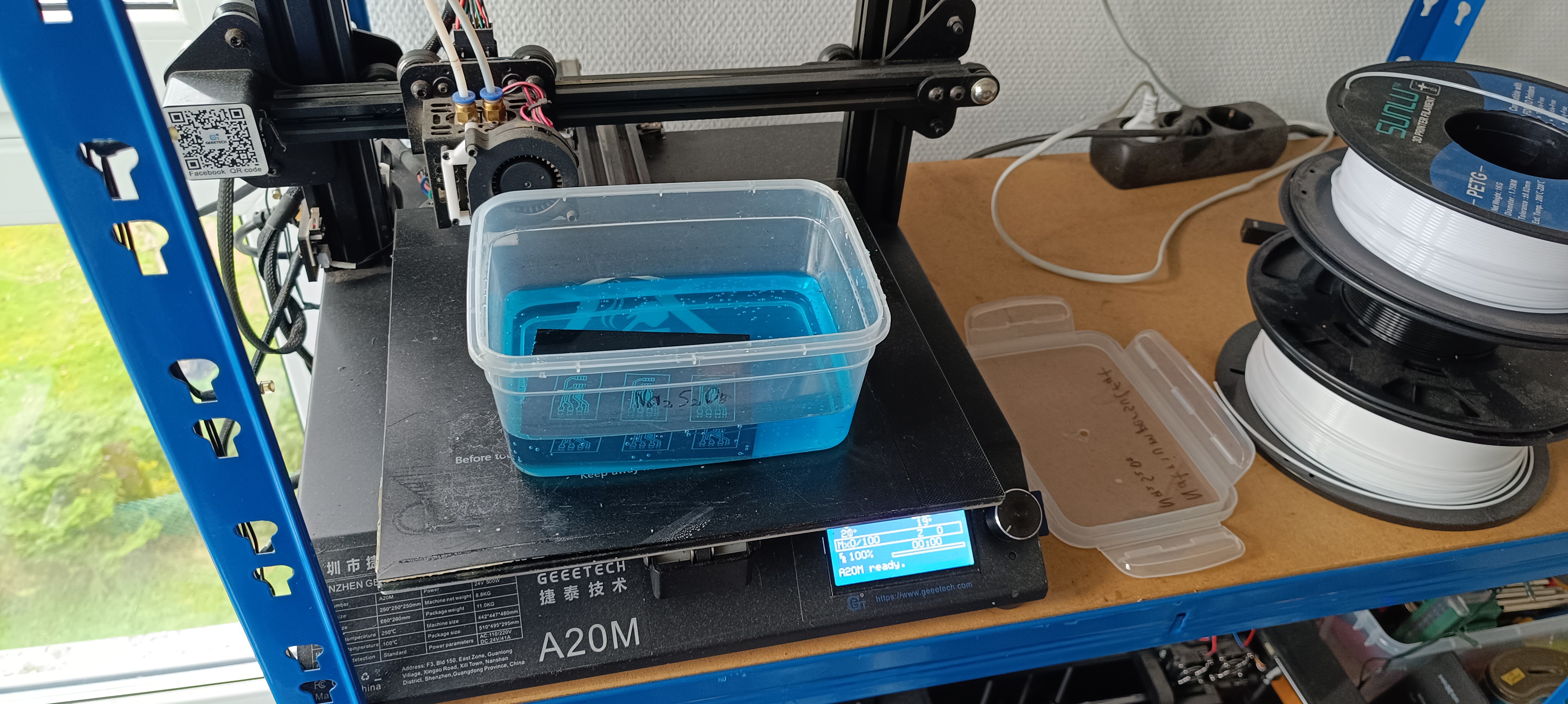
Some time ago, I bought a pulsed 1064nm IR laser (Sculpfun IR2) for metal engraving and I recently figured out that this laser is the perfect tool for removing spray paint from copper PCBs without any residue.
A year ago I tried the same with a common 450nm laser, but this laser rather burned the paint off while leaving a lot of residue on the PCB.
My guess would be that the pulsed operation mode of the new laser is the decisive factor here, which causes the paint to chip off or evaporate when hit with the laser instead of just getting burned away.
PCB Manufacturing Footage:
Laser in OperationPCB drawn in KiCad
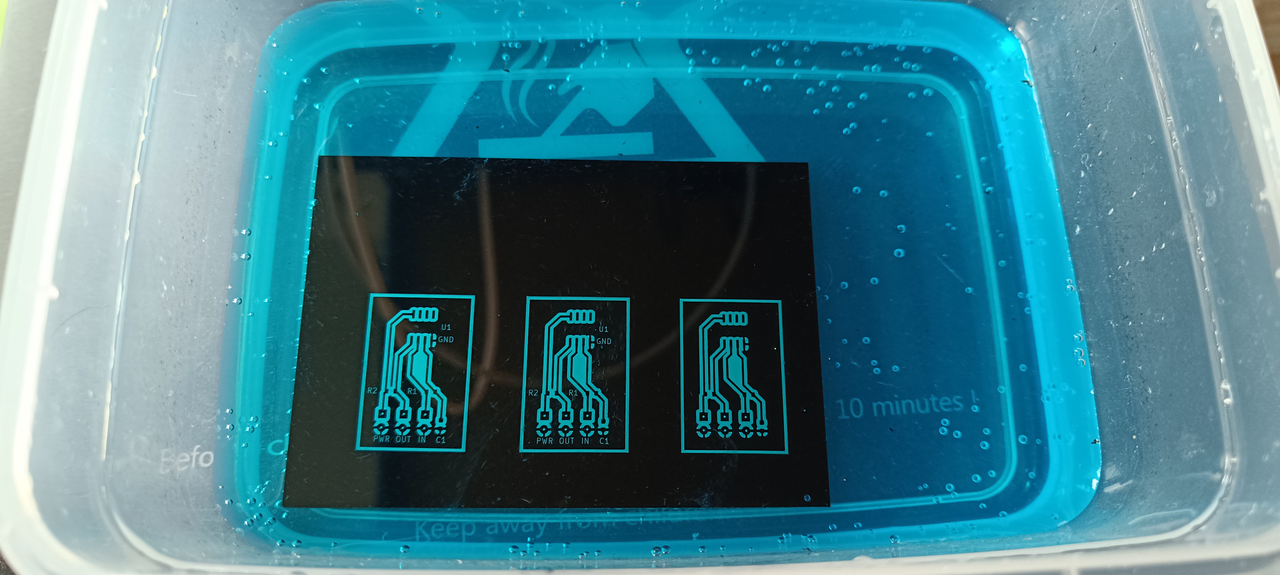
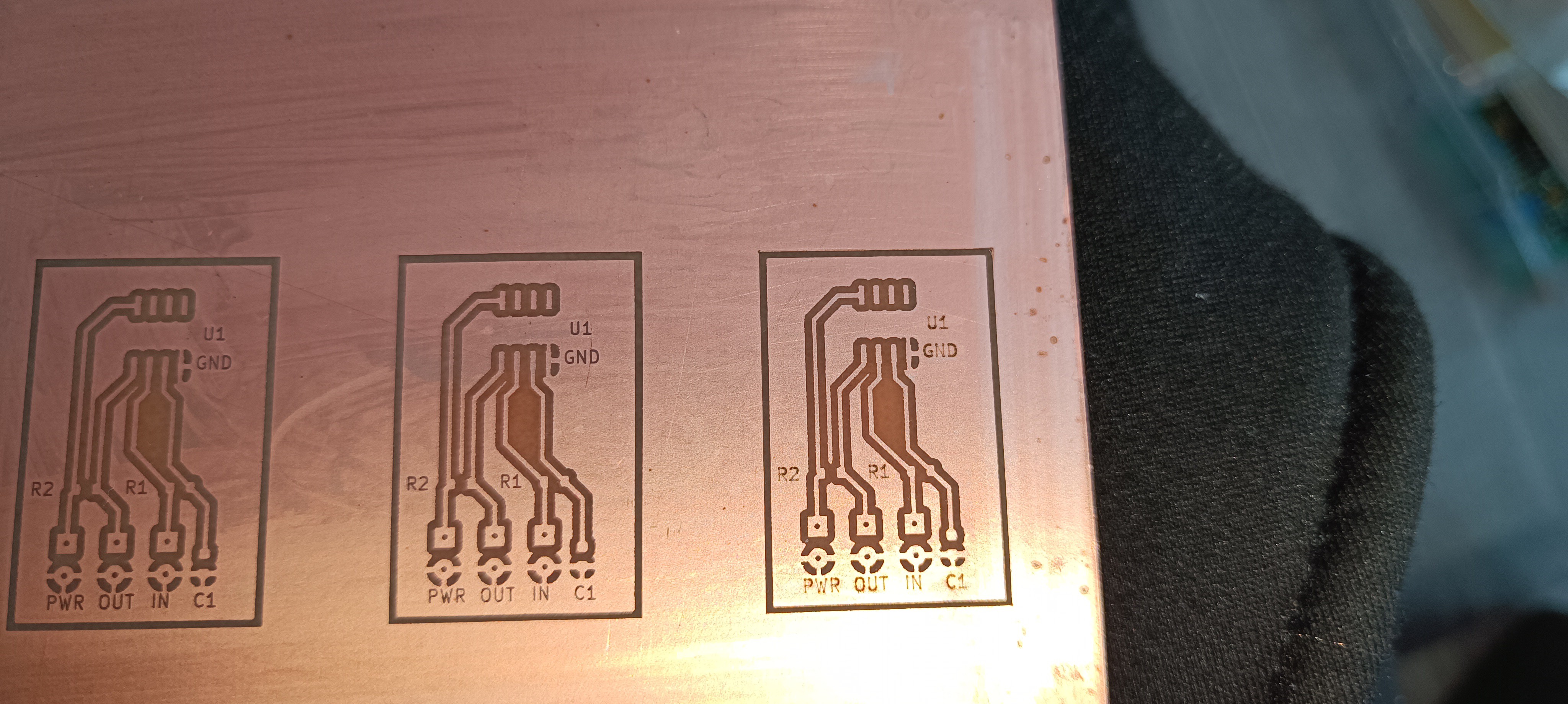
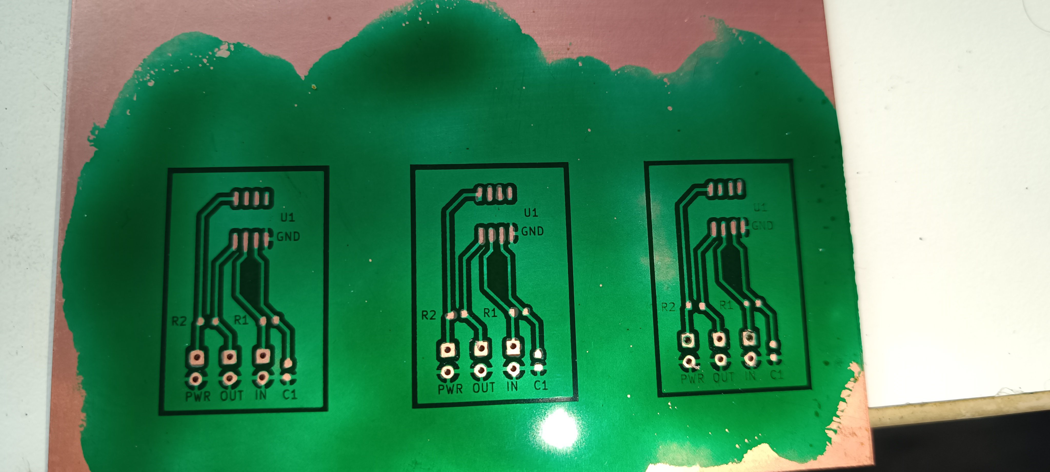
Lasered PCBPCB Etching in Sodium Persulfate
Heating the Solution for Faster Etching
Etched PCB
Paint cleaned off with Acetone
Applied UV Solder Mask
Cut out PCB with Components soldered in using Solder Paste and a Hot Air Solder Station
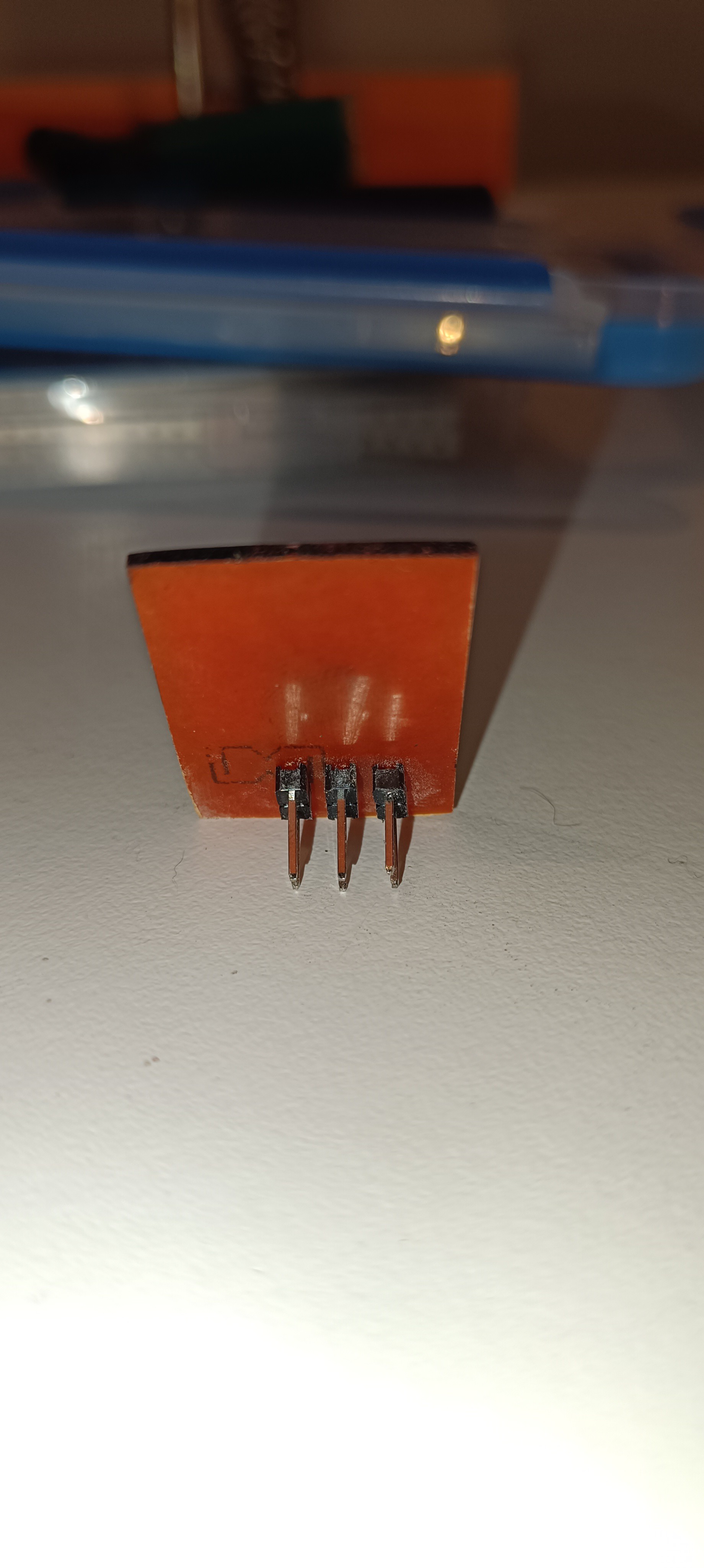
Backside with Pins - Later Designs got surface-mounted Pins to avoid drilling Holes
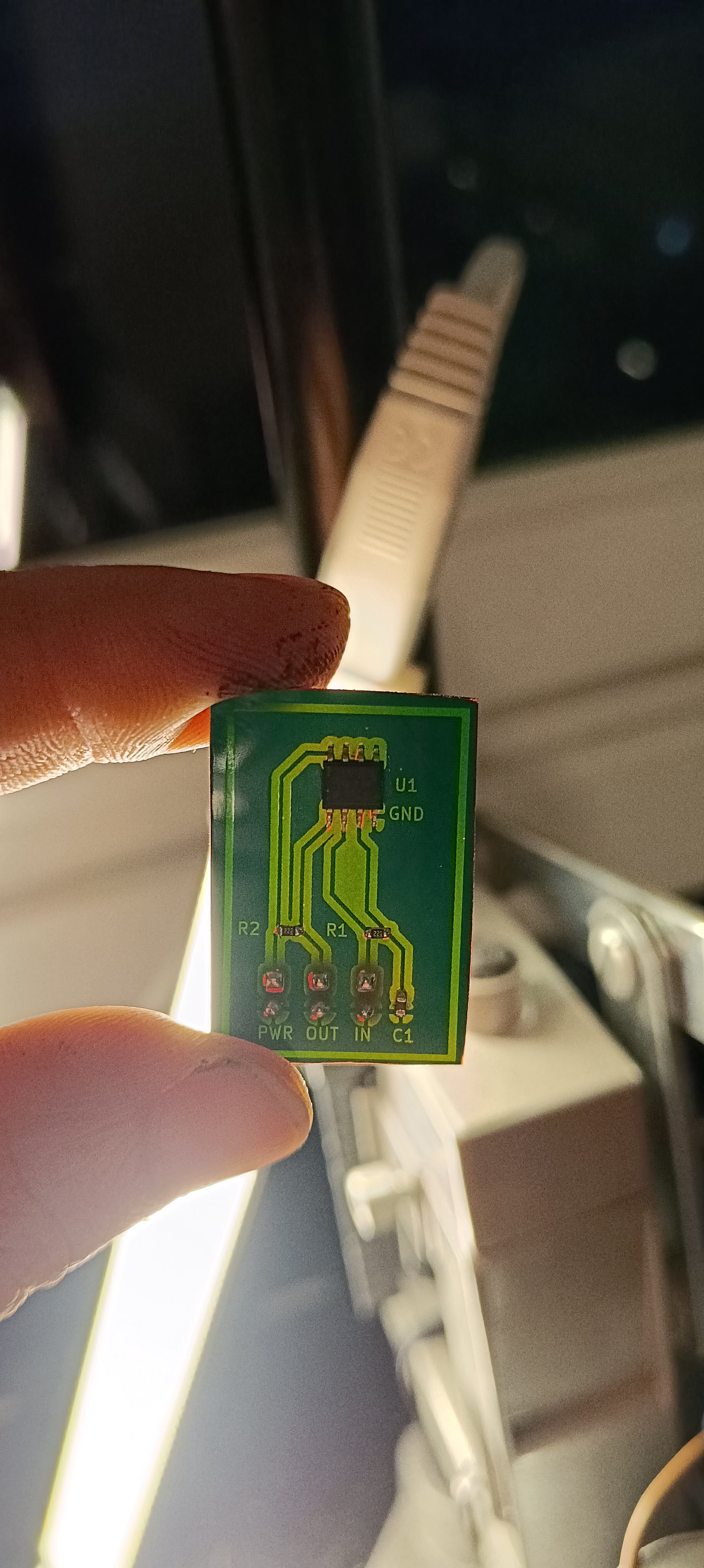
Finished PCB
I think having figured out a way of PCB manufacturing that works well for me will help move the project forward and will also be very useful for future projects.
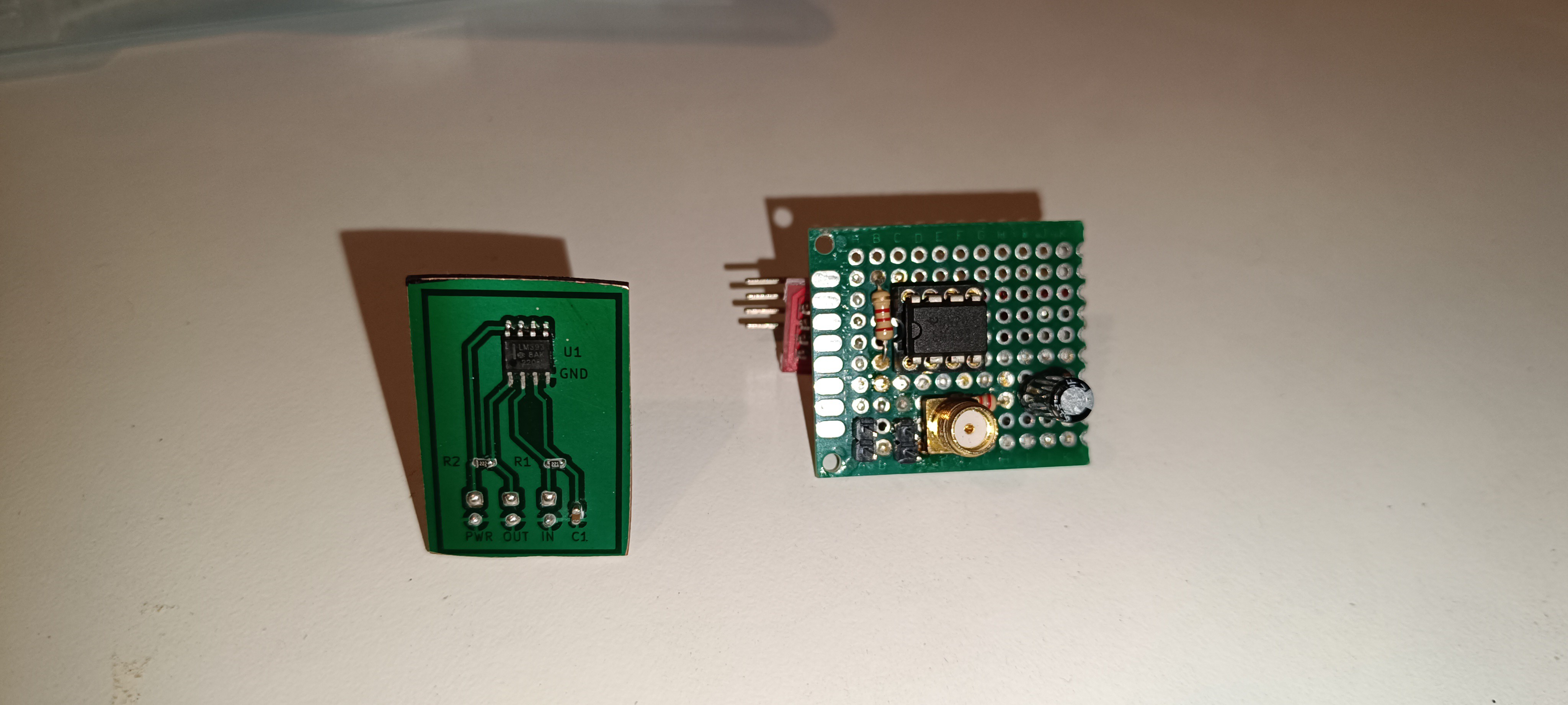
Until now, I always had to build circuits on perfboards and connect the components with solder wire. This was a lot of work and also looked ugly compared to the new design.
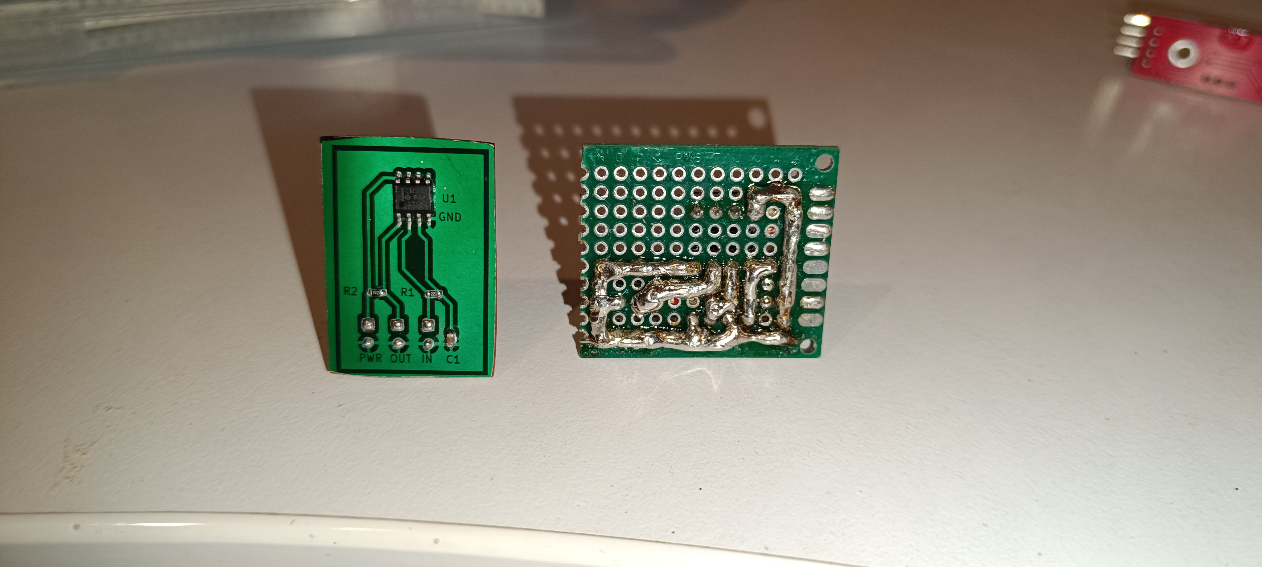
New Design VS Old Design (Front)
New Design VS Old Design (Back)
It's also an advantage that the circuit and PCB layout can be designed on PC for lasering it 1:1 onto the copper PCB.
This makes the process similar to 3D printing, which will make it easy to share the design with others and will ensure that each copy of it will be identical.
- I figured out a way of designing and manufacturing PCBs that works well for me so that it will be possible to build the needed circuits for the project as proper PCBs.
- I built a TL072-based amplifier by myself to replace the AD620 amplifier that I used so far, which never worked reliably. The new amplifier seems to work much better, while the amplification is currently very low.
- I built a test stand for the printhead, similar to the drop breakup test stand, but out of 2020 profiles and only 500mm high.
- I tried out many different resins for replacing the PVB and ended up using gum sandarac, which is plant-based and has better solubility, finish, and adhesion than the PVB.
- I added filters to the printer to keep the ink clean and prevent the lines and nozzle from clogging.
- I got a new oscilloscope that has 4 channels so that a trigger signal + the signals of the 2 new amplifiers can be displayed in the same timescale to verify that both work correctly.
Will try to write more buildlogs with text and footage of the work I did over the last months when I can find the time for it.
Future Plans:
I'm currently working on a time-of-flight counter for measuring the ink stream's velocity. This will ultimately be used for manual and later automatic pressure adjustments to compensate for changes in viscosity which appear when the machine is used after being off for some time.
Currently, the printer can measure a relative viscosity reading while heating/cooling the ink inside the printer to 25⁰C since the viscosity changes with temperature.
Hardware-wise, there is also a peristaltic pump installed for adding ethanol to the tank to compensate for evaporated ethanol and keep the viscosity steady.
While the feature is currently not activated, it would already be possible to use the viscosimeter reading for automatically adding ethanol.
The stream velocity reading + (auto) pressure adjustment will be used for a finer adjustment in addition to the viscosimeter which can bring the ink stream velocity to the right level immediately.
This, in combination with the viscosity regulation, the right piezo frequency, and the nozzle drive, will ensure that the stream breakup will always occur at the same position (inside the charge electrode).
Once a favorable piezo frequency, nozzle drive setting, and stream velocity are found, these settings can stay as they are since the TOF-based pressure compensation will keep the stream velocity constant at all times during operation and also when the machine is started again after being off for some time.
Even the older CIJ printer models use a TOF counter, so I think this will be a very important step in getting the machine running.
Once this is working, the next thing will be trying to get the phase test working again.
When I tried that last time, I had no way of knowing the ink stream velocity, so I worked with random conditions and only got random results.
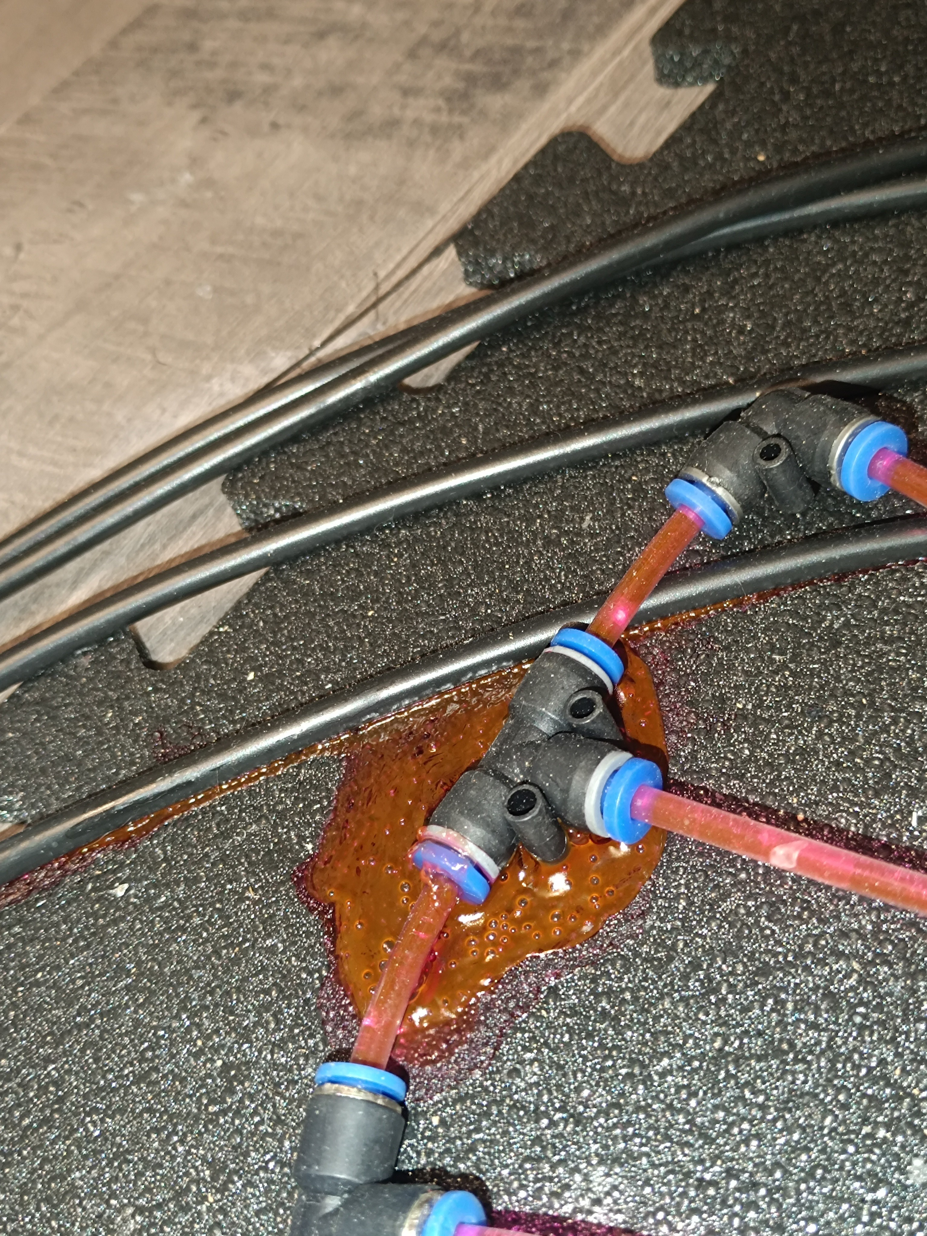
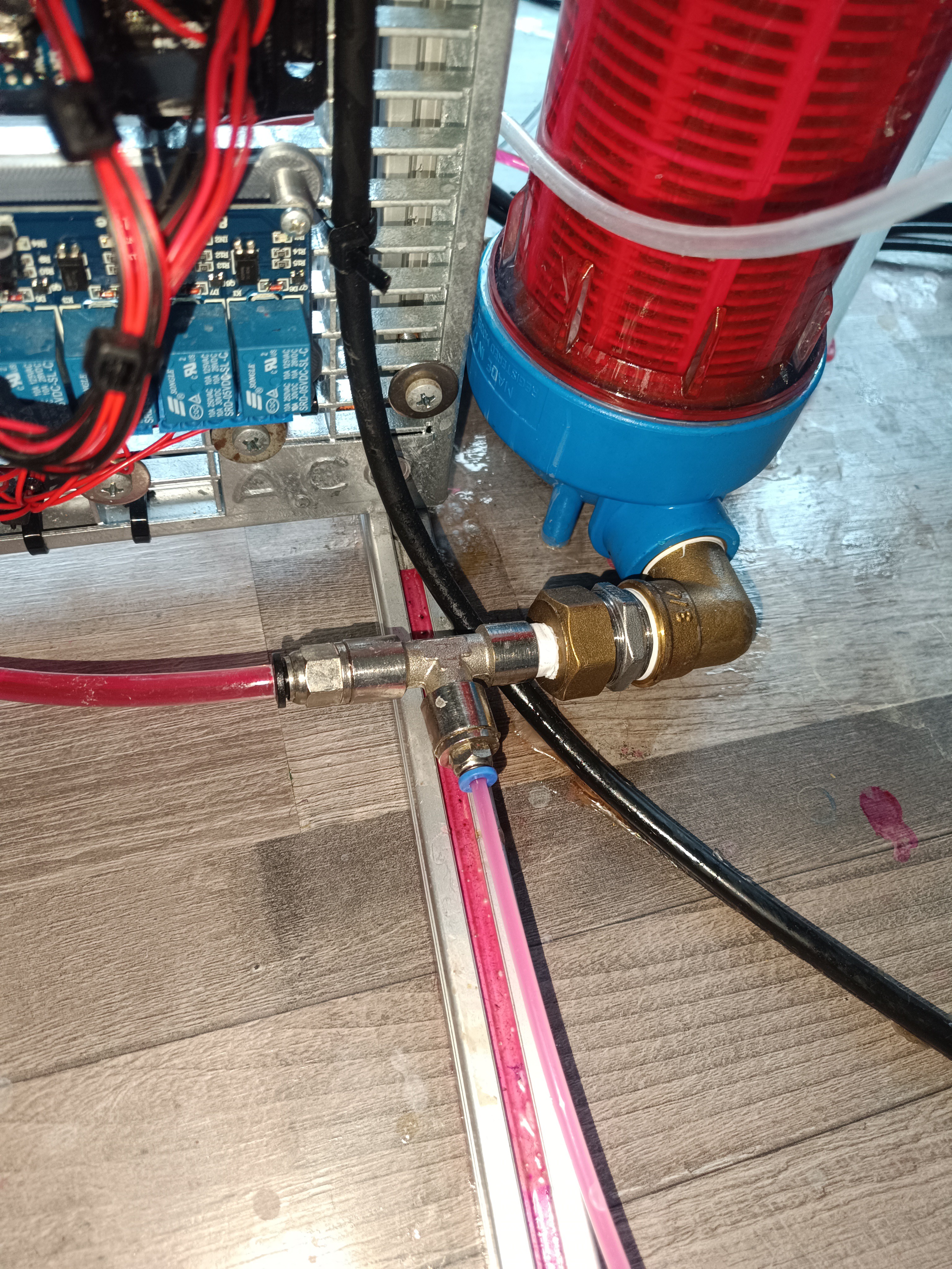
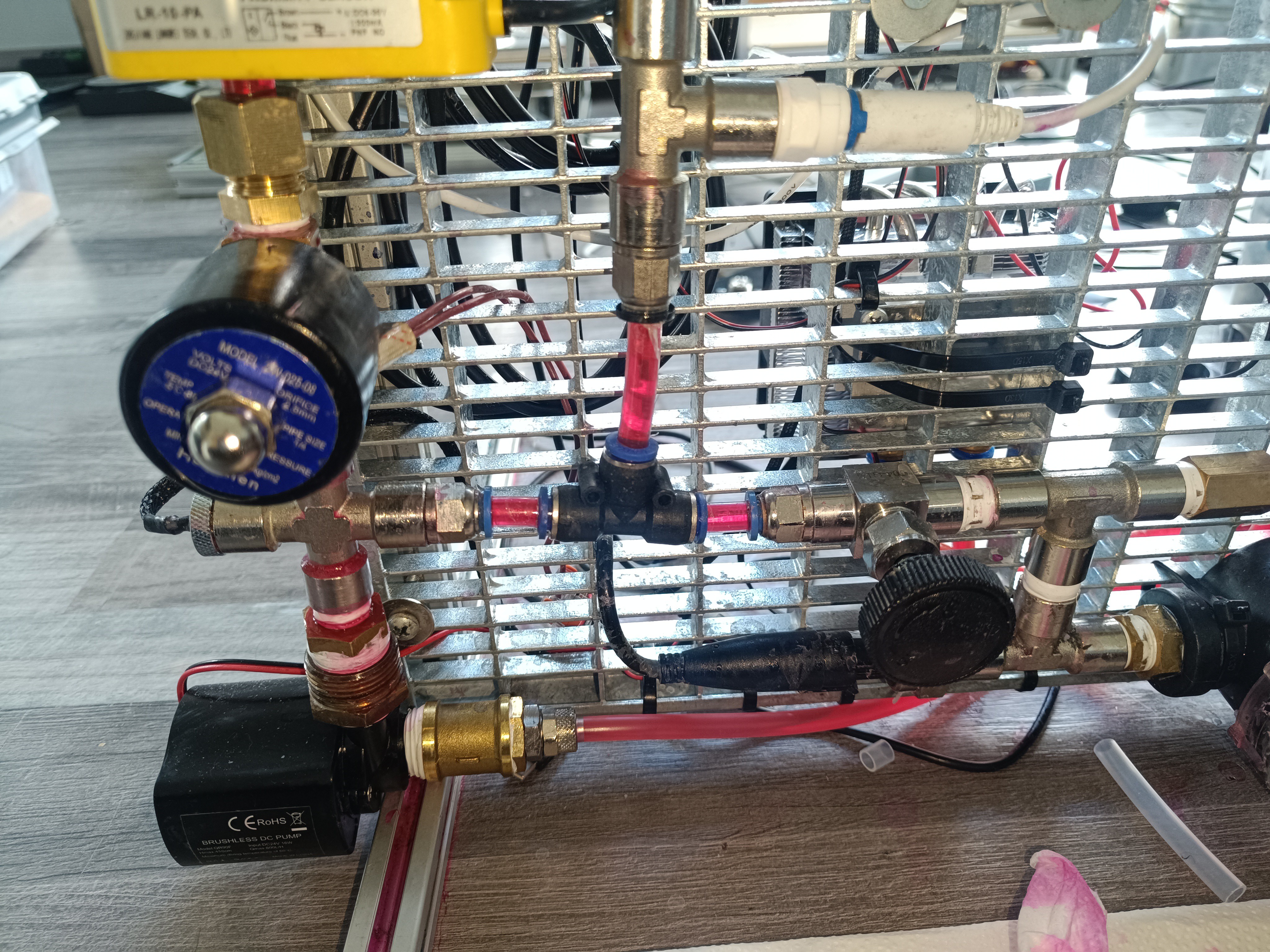
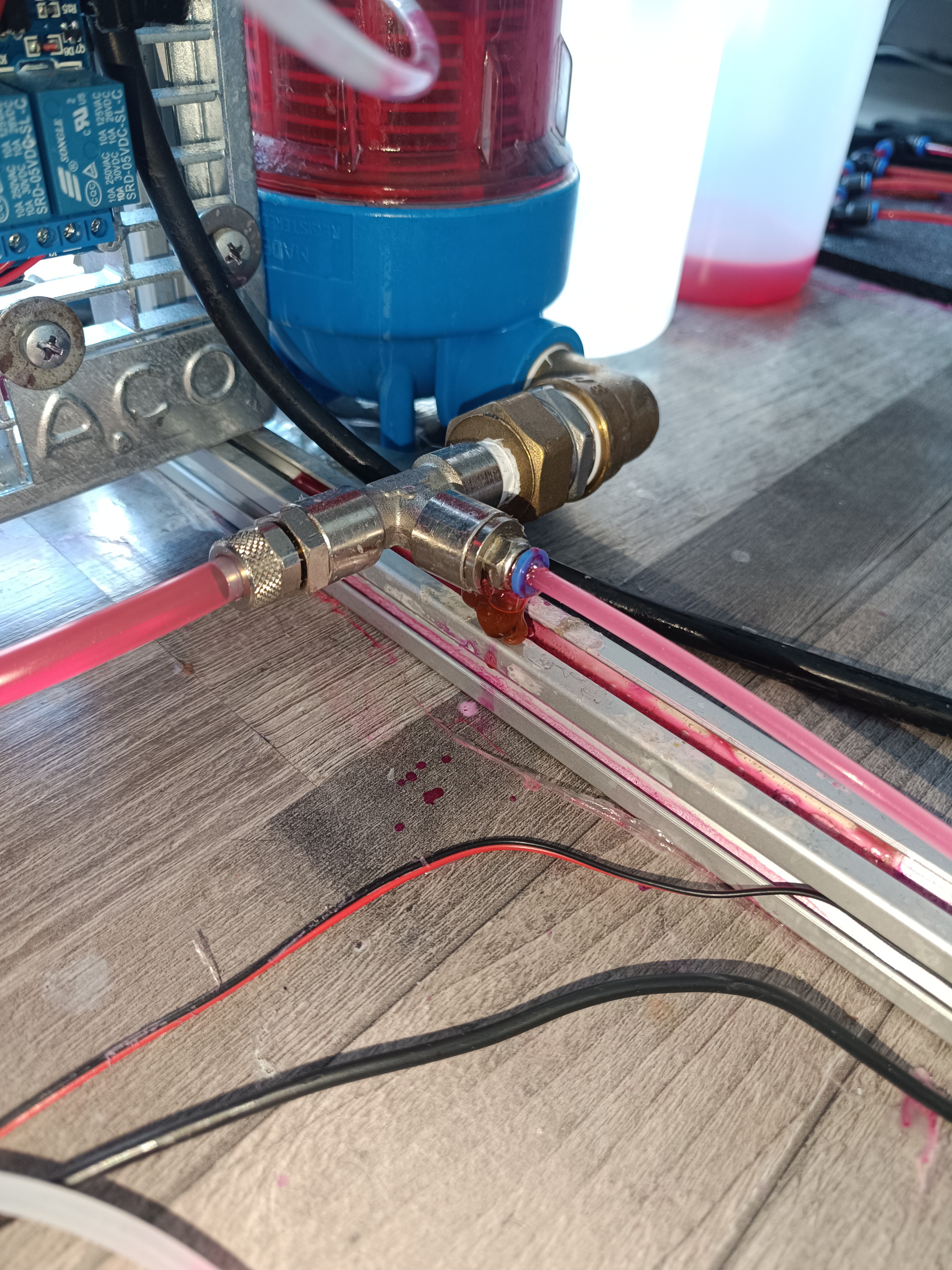
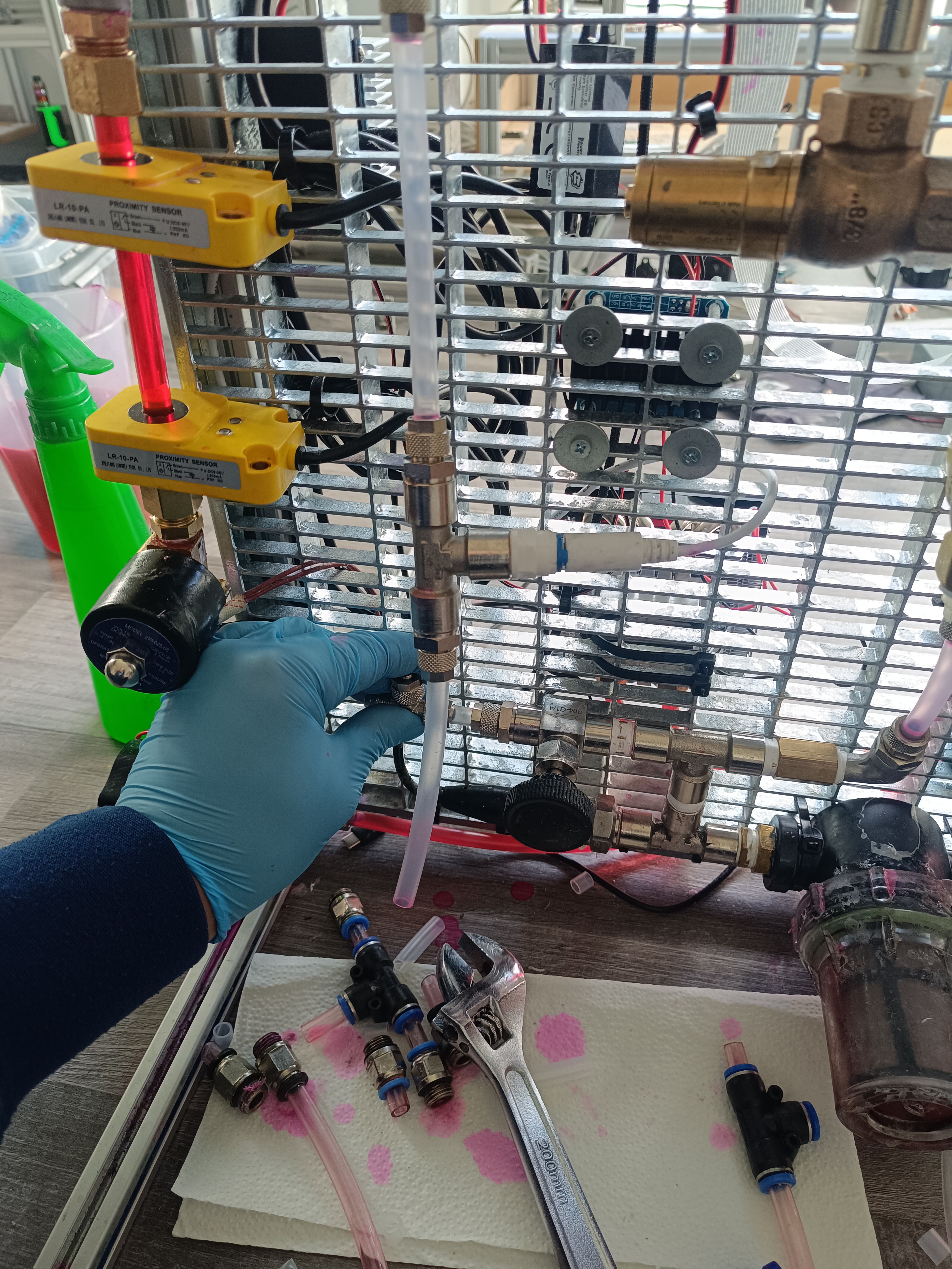
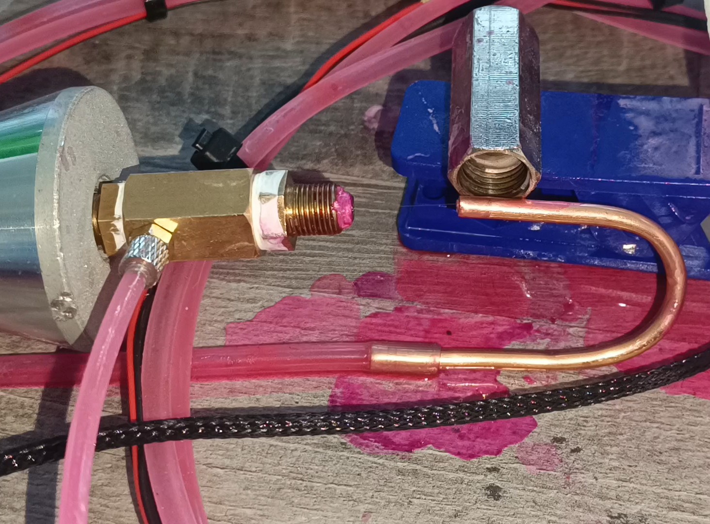
For the past months while working on the test stand and code for the ESP32, I did not use the printer prototype, and while it was standing there, some of the fittings got leaky.
Leaky T Fitting
Until now, it wasn't that big of a deal that the fitting's NBR seals got dissolved by the ethanol over time, because I changed the prototype's design over and over again, and with it the fittings, but after a lot of testing I thought that most parts of the current design were working reliable enough to keep them this way so that it was finally worth it to replace the push-in fittings with a more suitable type of fitting.
A better option than the pneumatic push-in fittings are CK fittings (sometimes also called rapid screw fittings), which don't have a seal that can get leaky but instead use the tube itself as the seal by clamping it between the two halves of the fitting.
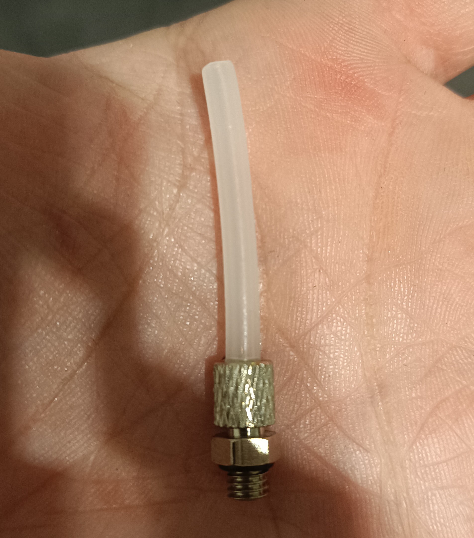
Since I had to replace every fitting connection on the printer, I also wanted to replace the currently used PU tubes with PE tubes, which in contrast to the PU tubes, are suitable for long-time exposure to ethanol because of their better chemical resistance.
CK Fitting with PE Tube
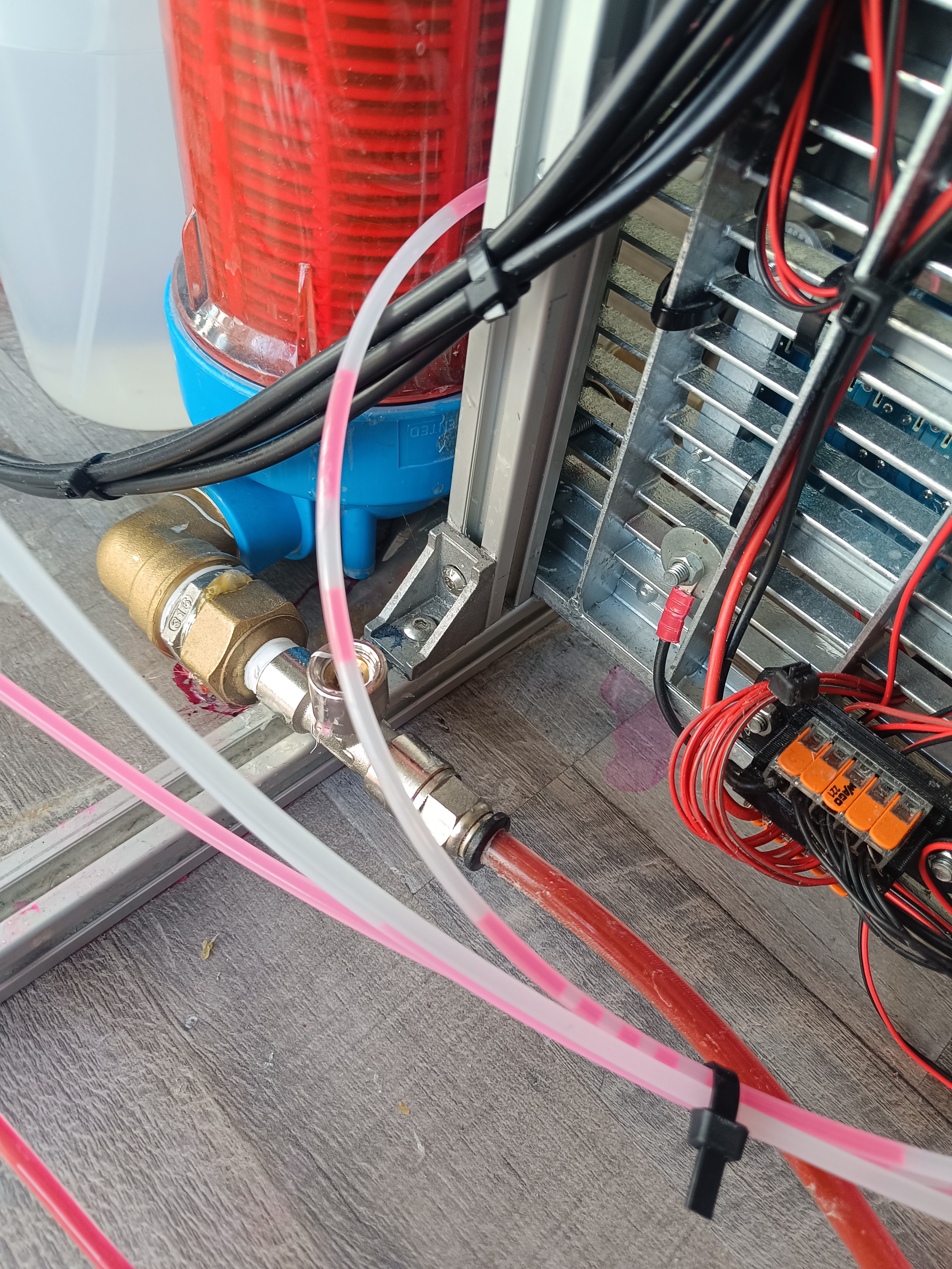
No more Watercooling
While I was replacing the fittings and tubes, I also thought about replacing the water cooler with an air cooler, so I could get rid of the water cooling pump, radiator, reservoir bottle, and tubes to end up with more space for other parts and less cost and complexity.
Until now, the water cooler was used to get rid of the heat of the Peltier module when it's used for cooling the ink.
The Peltier module can be used for heating or cooling the ink depending on the room temperature to always keep the ink on a reference temperature of around 25⁰C for viscosity measurement.
The ink's viscosity changes with temperature even if the ink mixture stays the same, so it's necessary to always measure the viscosity at the same temperature to be certain that changes in the viscosity reading also represent changes in the ink mixture.
To keep the viscosity constant during printing, the printer can add more ethanol to the mix to compensate for the evaporation of ethanol, which would otherwise lead to an increase in the ink's viscosity.
As long as the room temperature doesn't exceed 25⁰C by a lot there wouldn't be much heat to dissipate, so I think the cooling can be handled by an air cooler as well for the most time of the year.
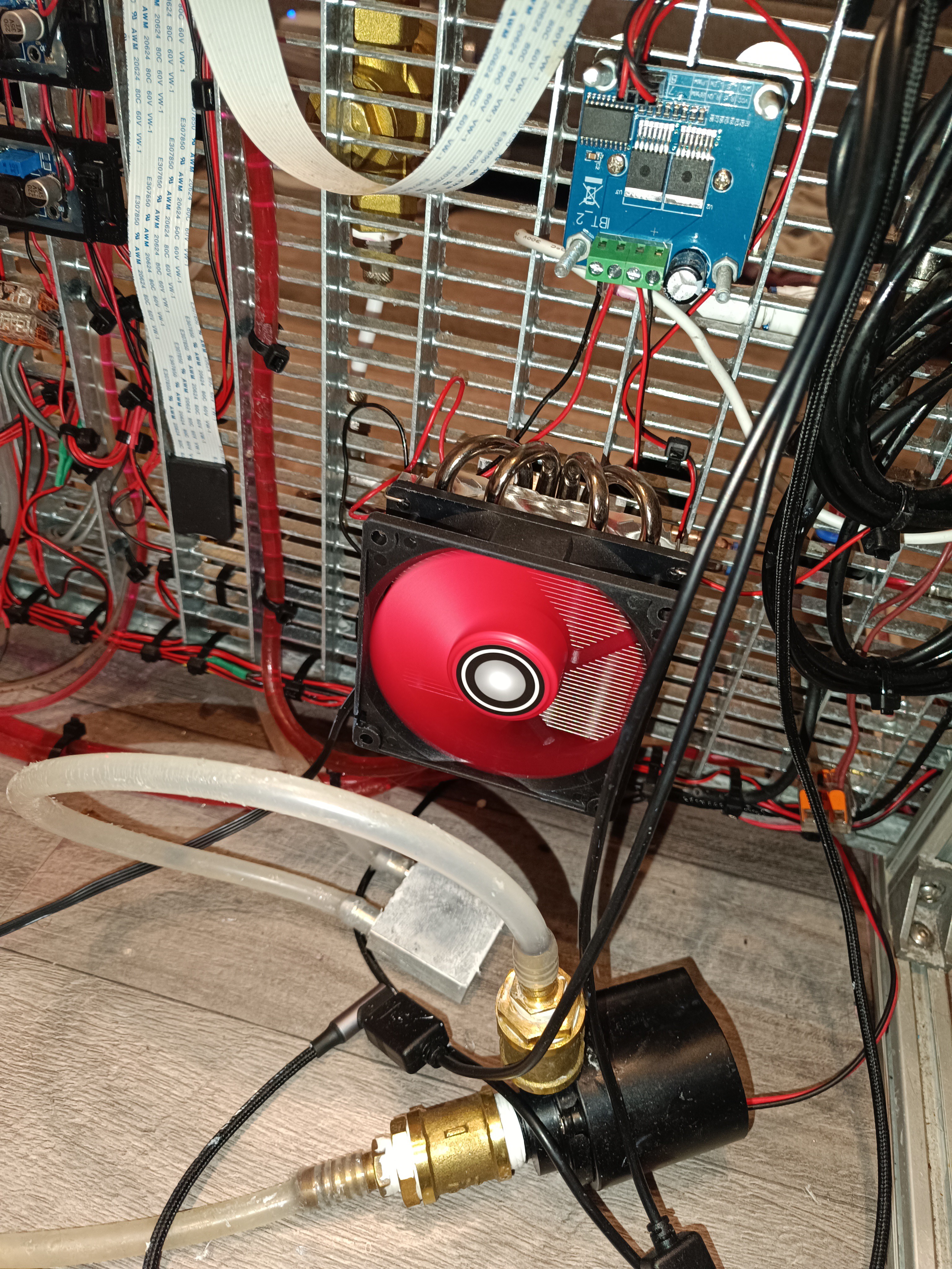
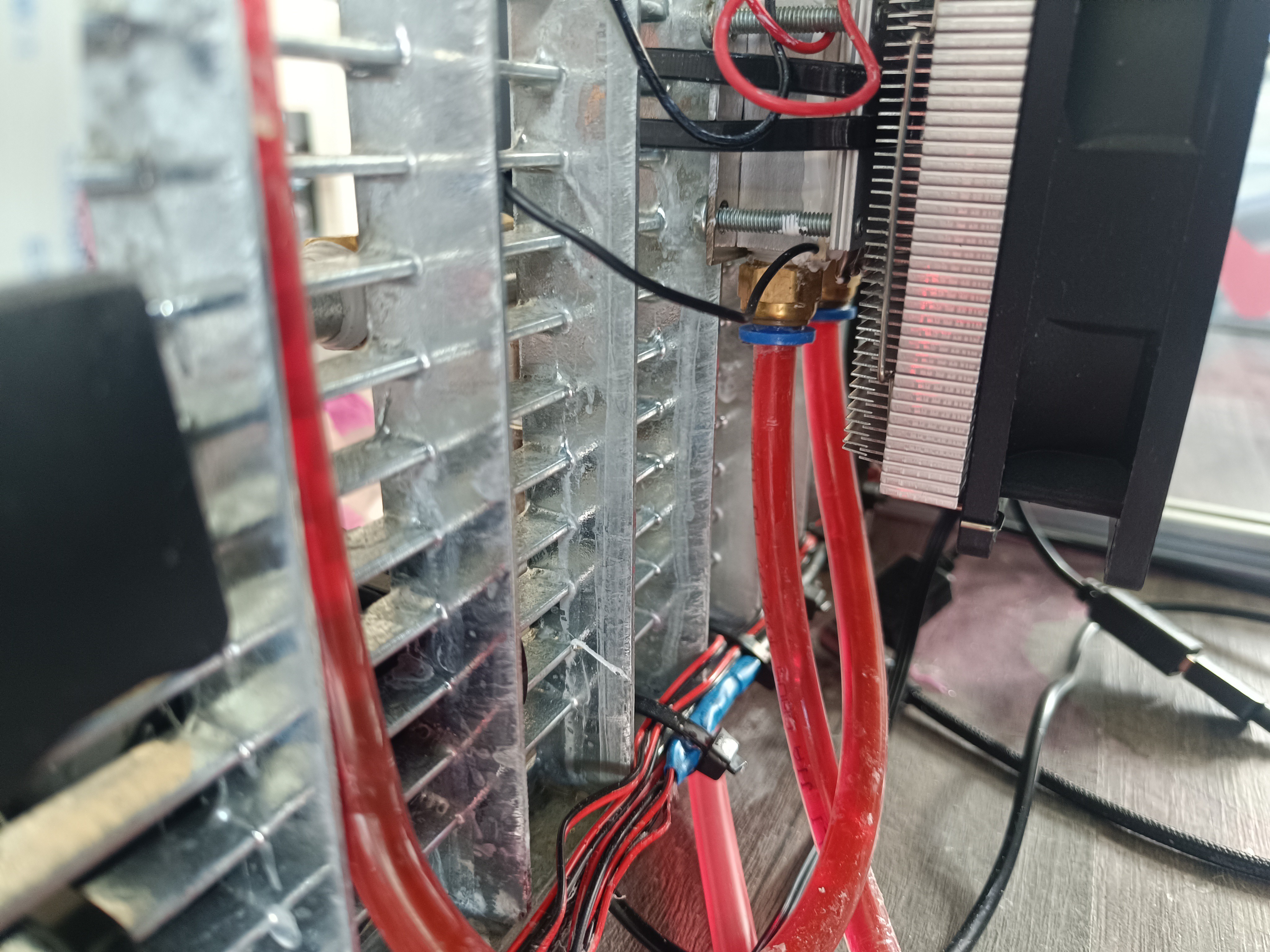
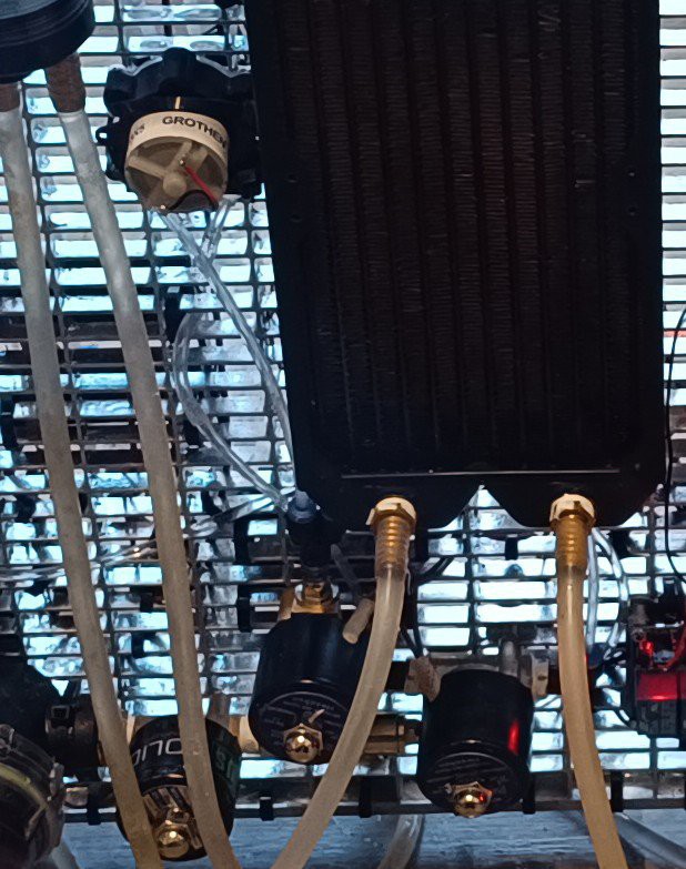
So, I replaced the water cooler with an air cooler.
Air Cooler, old Heat Exchanger, and old Pump
New Flushing Concept
A while ago I added a flush valve and flush line to the printhead that could be used for flushing the nozzle and gutter line with ink for cleaning.
Old Flush Valve and Flush Line
It turned out that this wasn't the best idea because the ink would harden inside the tubes when the printer is not used for some time and when I recently ended up with clogged lines that I had to replace, I decided to change the printer design in a way that makes it possible to draw all ink from the nozzle and gutter line via vacuum and then flush these lines with ethanol without adding unwanted ethanol to the ink tank.
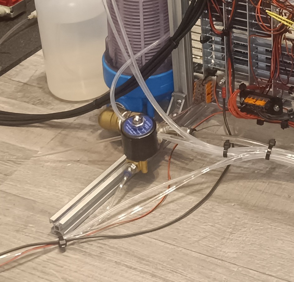
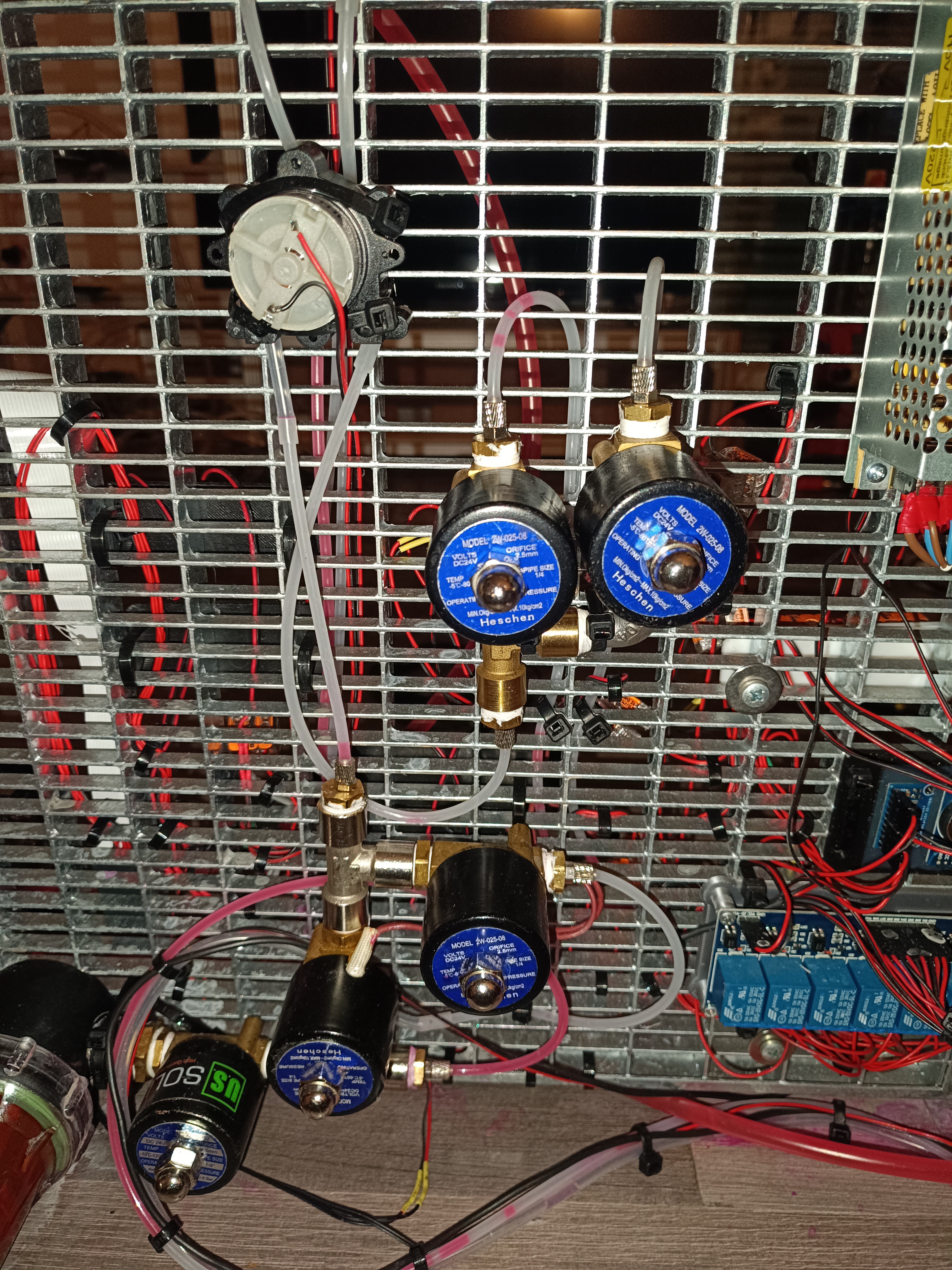
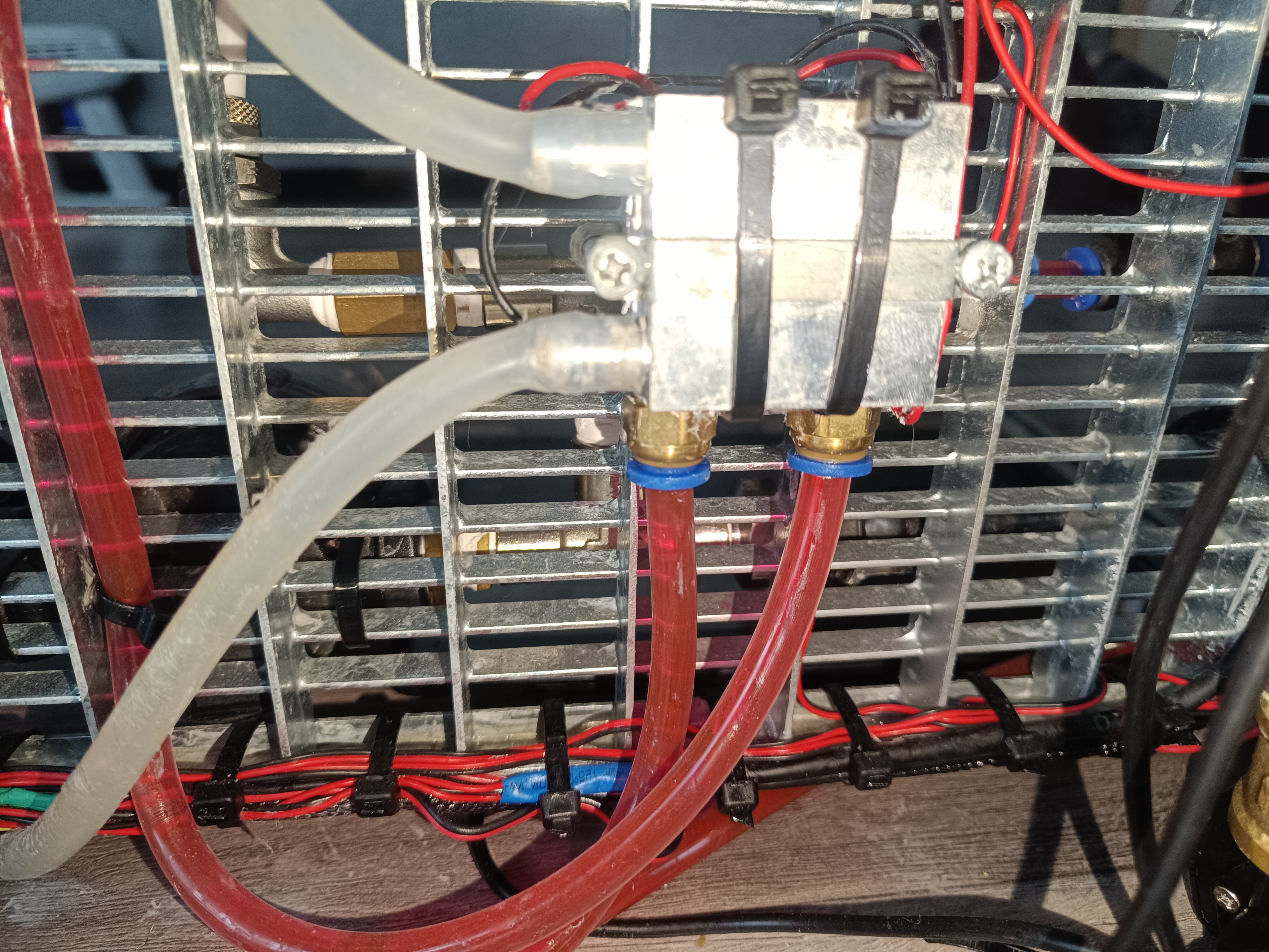
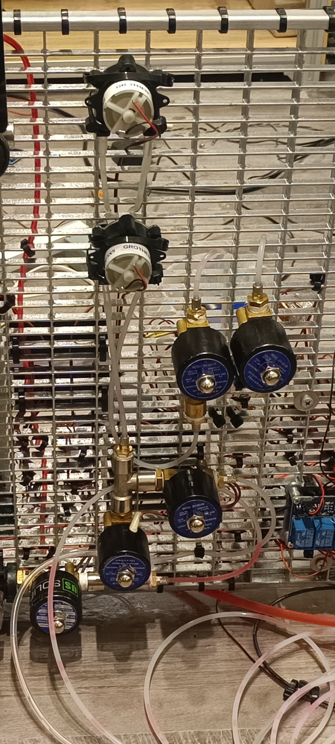
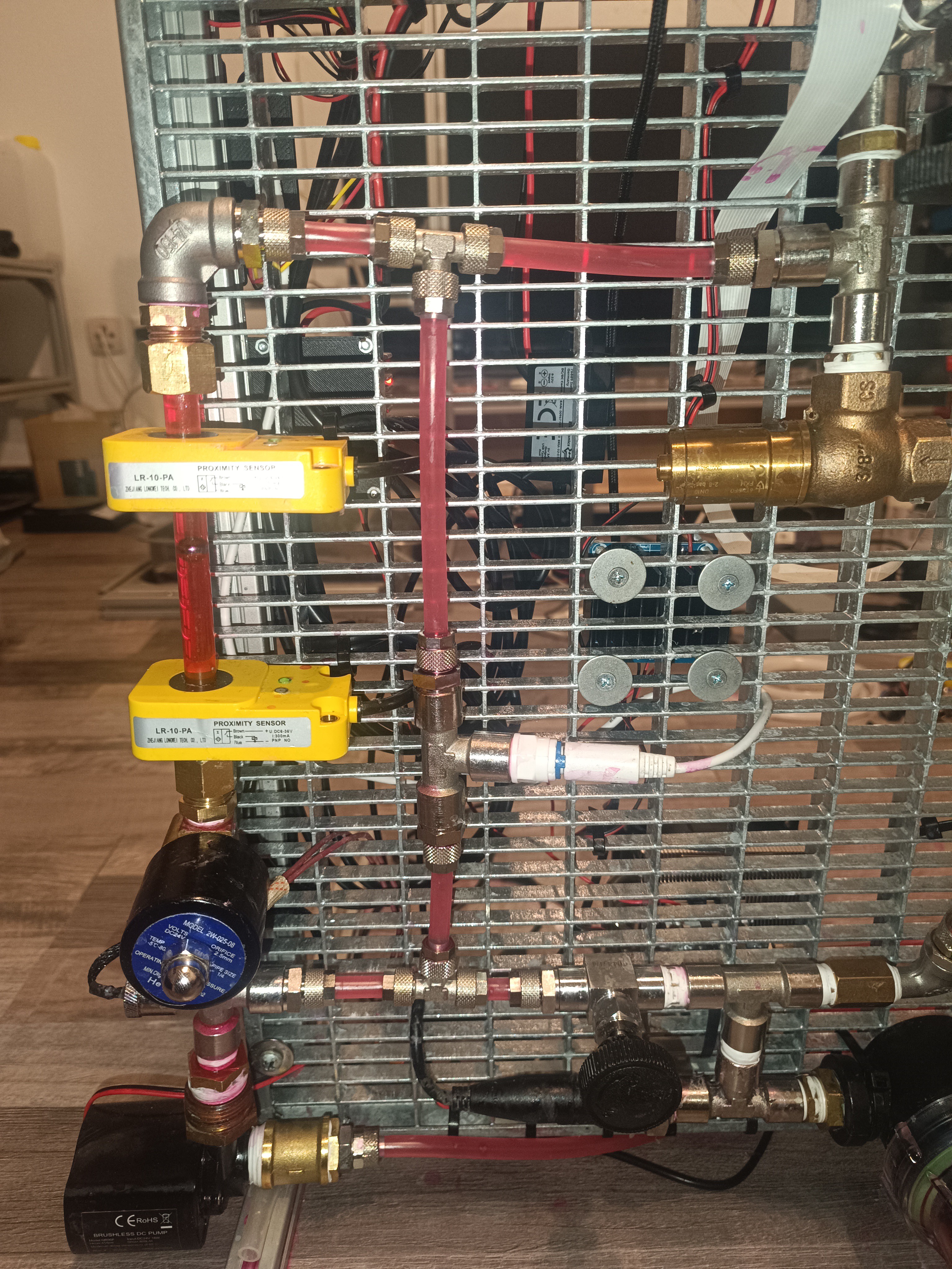
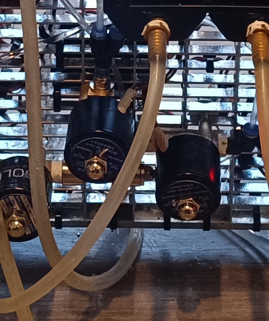
To do so, I added two valves to the output of the return pump, which are both switched with the same relay. The valve that leads to the ink tank is connected to the normally closed pin and the valve that leads to the flush bottle is connected to the normally open pin so that the ink flows into the ink tank until the flush line function is activated which switches the relay so that the ink tank valve closes and the flush bottle valve opens.
From Bottom to the Top: Nozzle Ink Valve, Nozzle Vacuum Valve, Gutter Valve, Ink Tank Valve, Flush Bottle Valve
With this change, it's possible to flush the gutter and nozzle line into the flush bottle to prevent clogged lines and too diluted ink in the future.
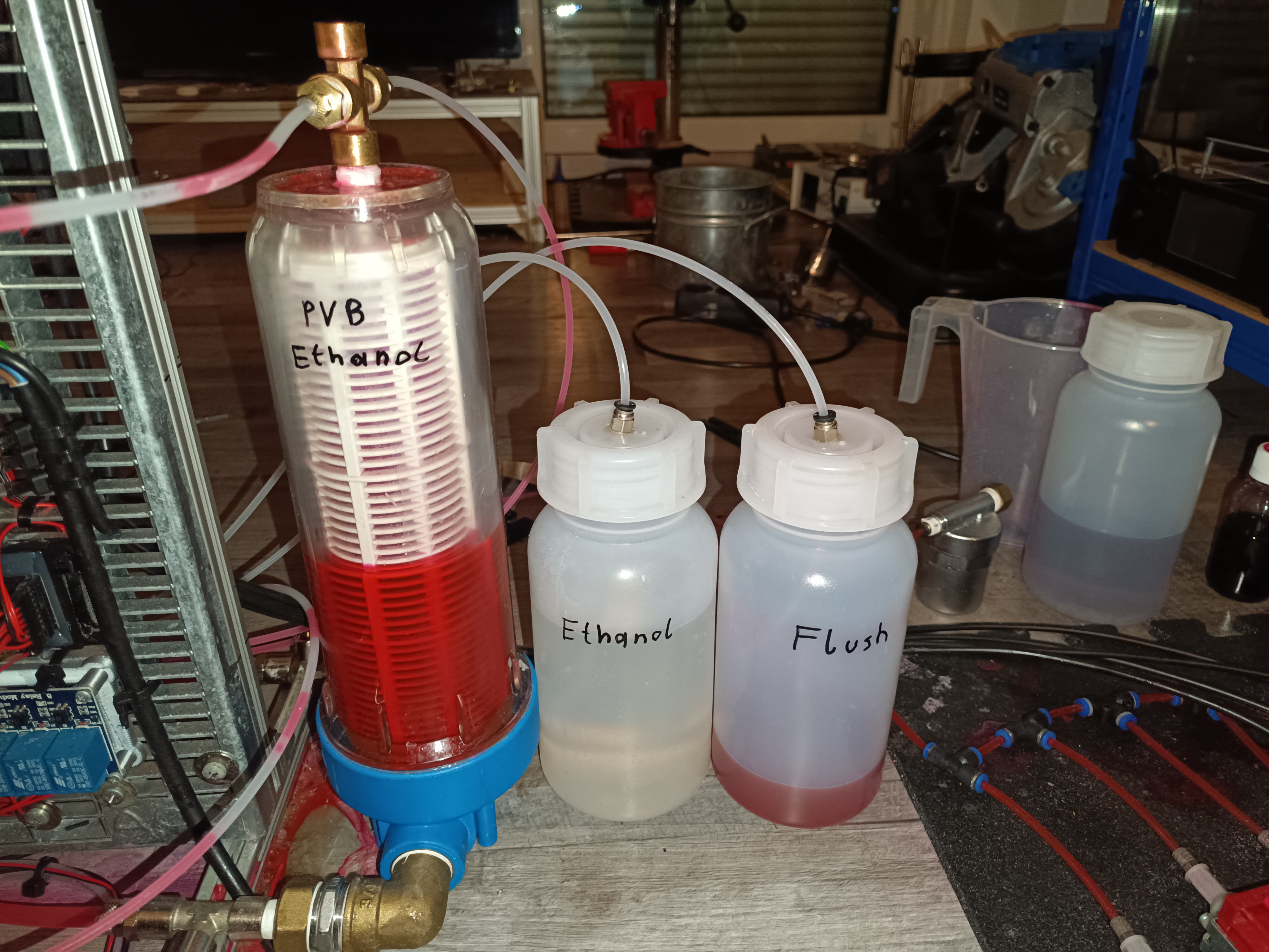
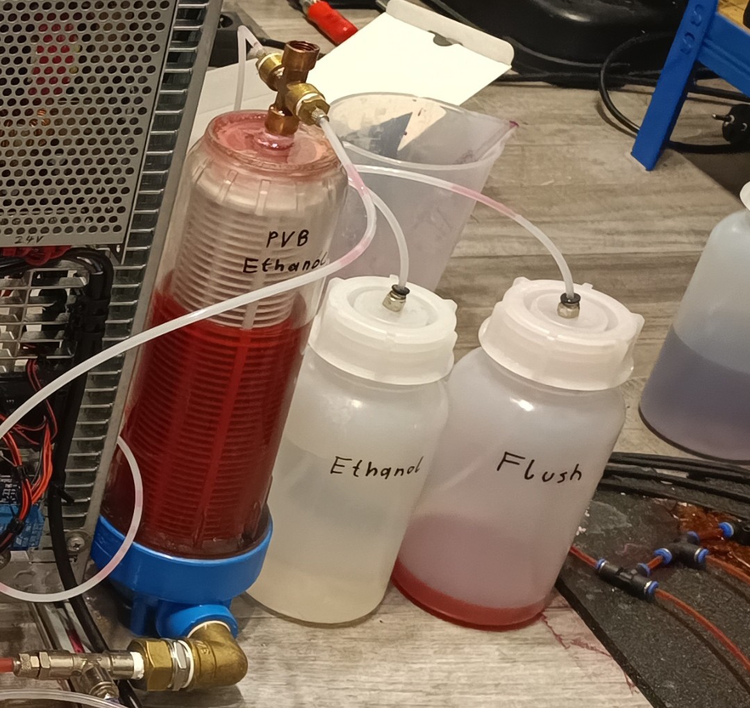
Ink Tank, Solvent Bottle, and Flush Bottle
Some Footage
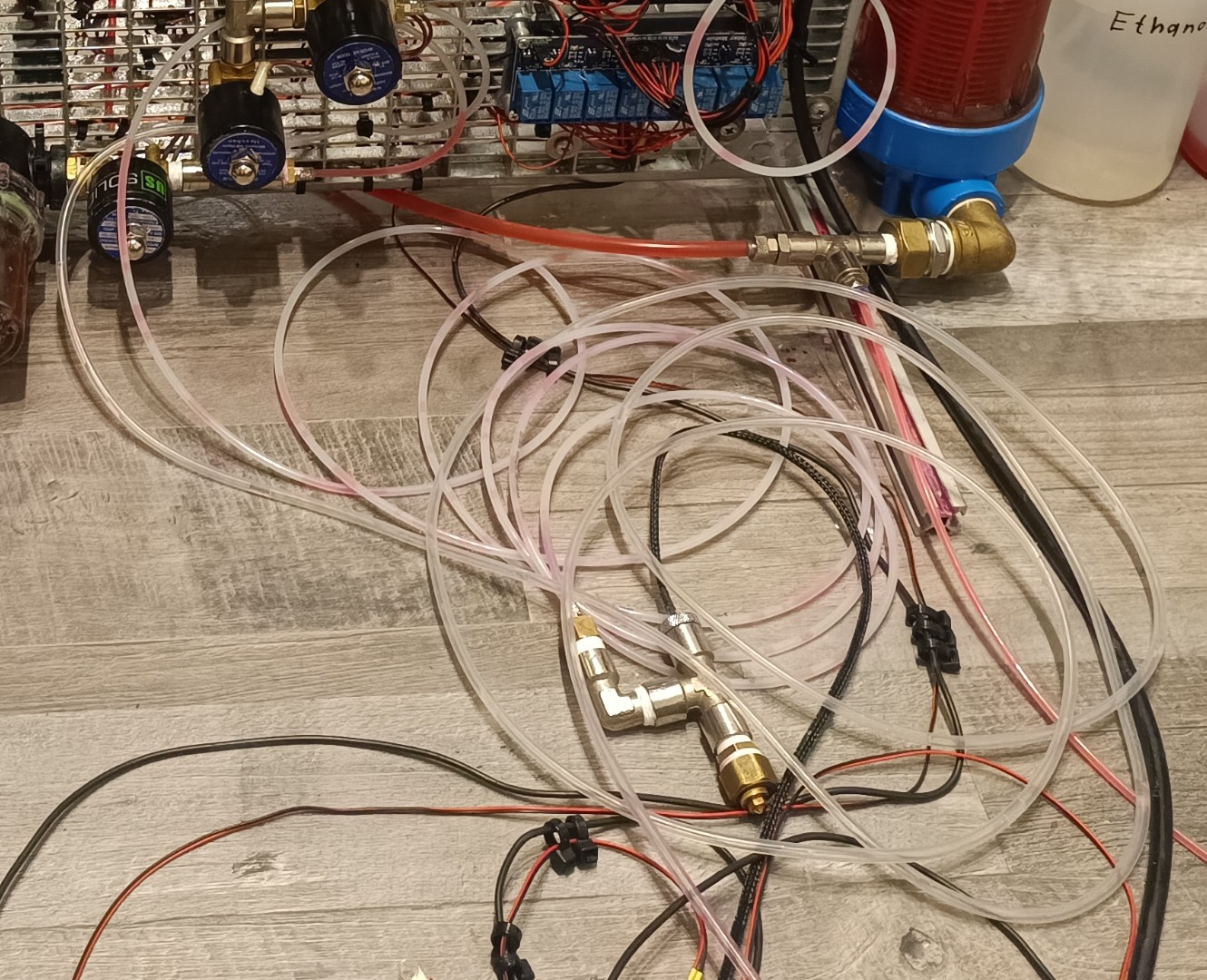
Here are some photos I took while replacing the fittings and tubes:
Printer with old Fittings, PU Tubes, and Water Cooler
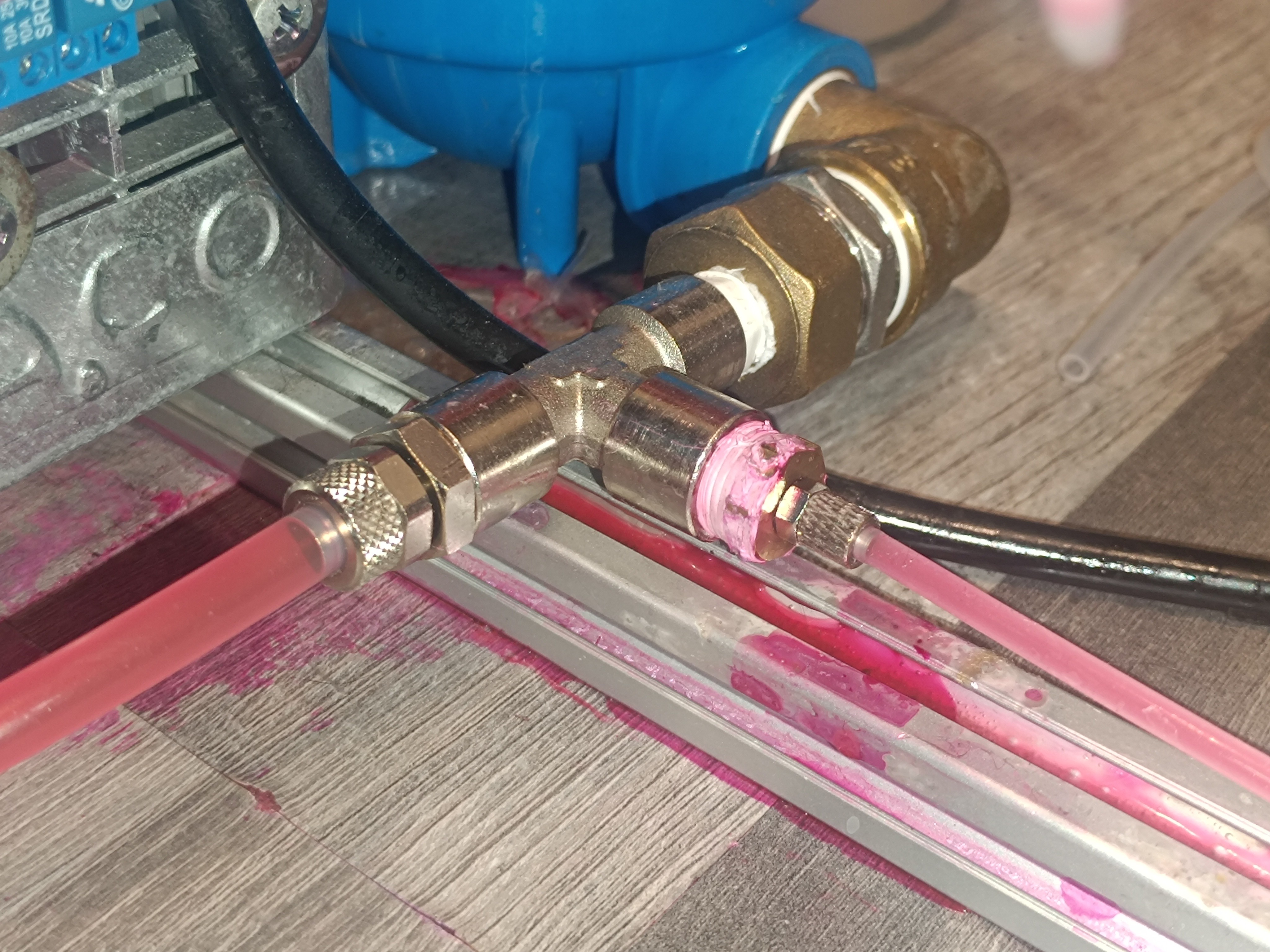
Leak on one of the Pressure Pump's T Fittings
Replaced the 4mm Tubes on the Bottom with a 1/4" T Piece
Added a Valve for taking Ink Samples
Gutter Valve Connected via T Fitting
Old Push In-Fittings
Old Flush Valve
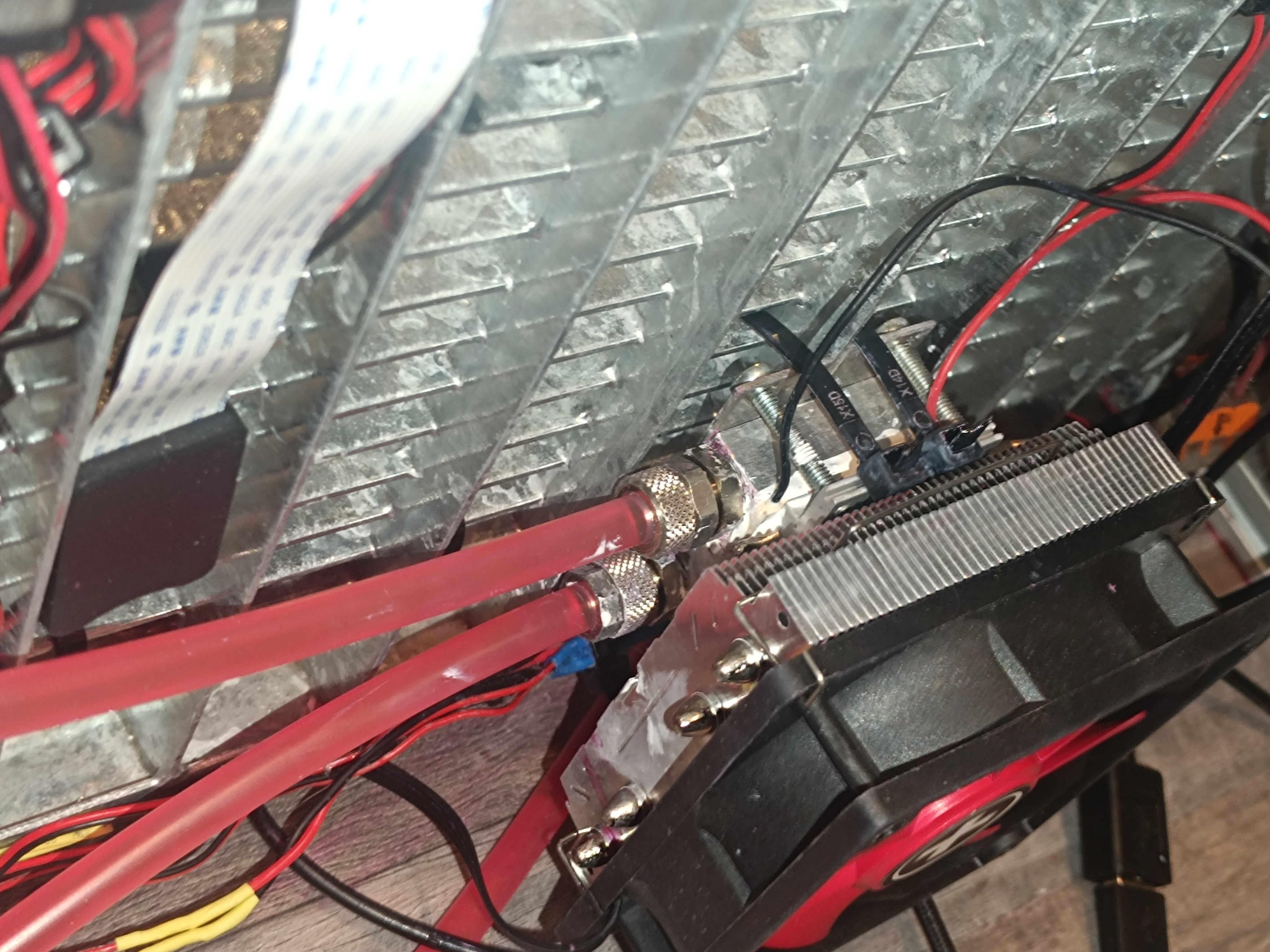
Watercooling Heat Exchanger and Ink Heat Exchanger with old Fittings
Viscosimeter Polycarbonate Pipe with Compression Fittings
New Air Cooler
Printer with Flush Bottle, new Valves and Aircooler
Pump with 8mm CK Fitting
4mm PU Tubes replaced with 4mm PE Tubes
Tubes connected with 4mm M5 CK Fittings
8mm CK Fitting on the Tank and 4mm PE Tubes
Ink Tank with 4mm CK Fittings
Circulation Line with CK T Piece and CK Fitting on the Conductivity Sensor's T Piece
Old 8mm Push In Fittings
New 8mm CK Fitting and old 4mm Push Fitting on the Ink Tank
T Piece with the old Flush Valve removed and old 8mm Fitting
Old 1/8" 8mm Push-In Fittings on the Ink Heat Exchanger
Replacing PU with PE Tube and Push-In Fittings with CK Fittings
All Push-In Fittings were replaced with CK Fittings
New CK Fittings on the Tank with 8mm going into the Circulation Pump and 4mm going into the Pressure Pumps
New 1/8" 8mm CK Fittings on the Heat Exchanger
Backside with the PU Tubes replaced by PE Tubes
Pressure Pump Lines were kept as they are because while they are working ok, this Part is still not perfect and will likely change at some Point
Printer with new Lines and Fittings
Working on a new Printhead
With the improved printer, it is now possible to focus on the printhead and charging component without the constant need to repair parts of the ink management component before every test.
New Printhead
I started building a new printhead, this time leaving the piezo transducer in one piece for using the piezo ring stack as it is intended to be used. My idea is that it could transfer the vibration better to the ink stream with the two piezo rings and the metal body. I think that with the last design, a lot of the vibration got dampened because of the more flexible plastic body. The new design will likely be more efficient, so it should be able to break the ink stream into drops even with a lower voltage since the piezo transducer is quite oversized for the task (Normally, the piezo rings used for that are much smaller, while using a higher voltage).
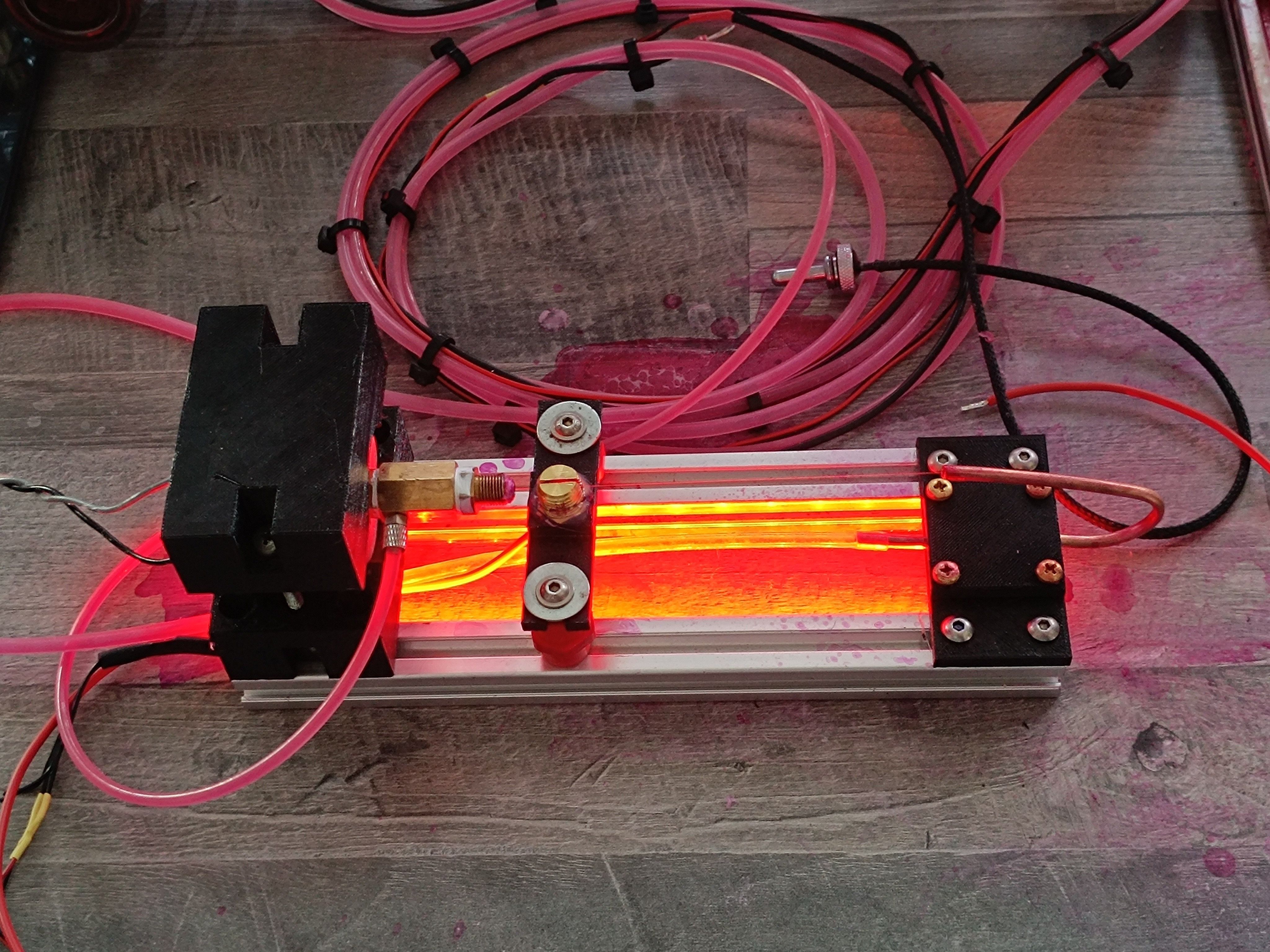
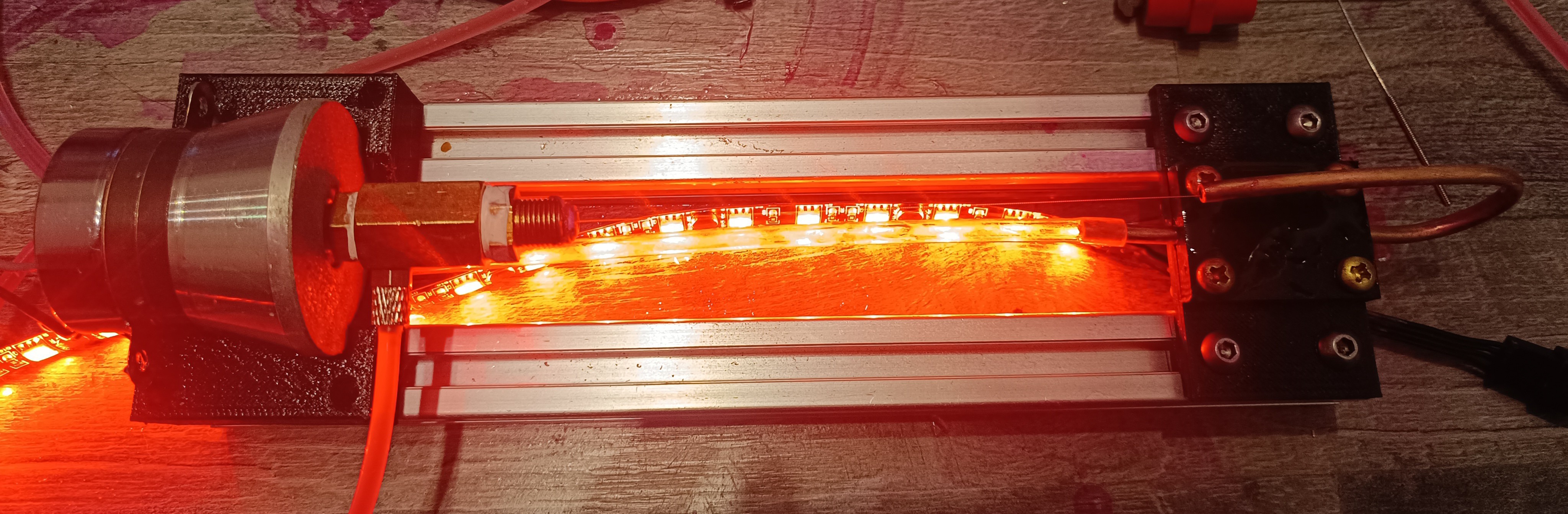
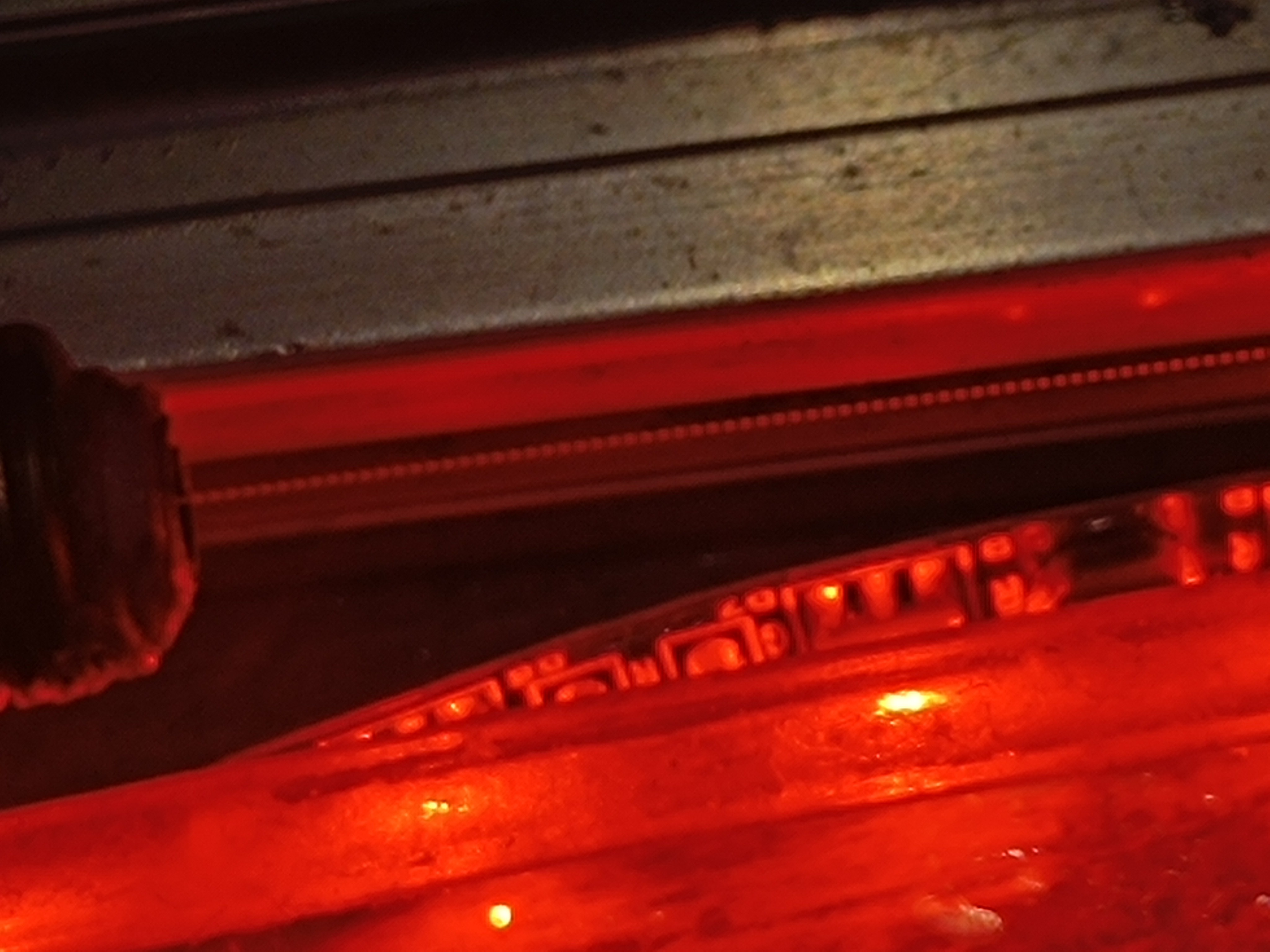
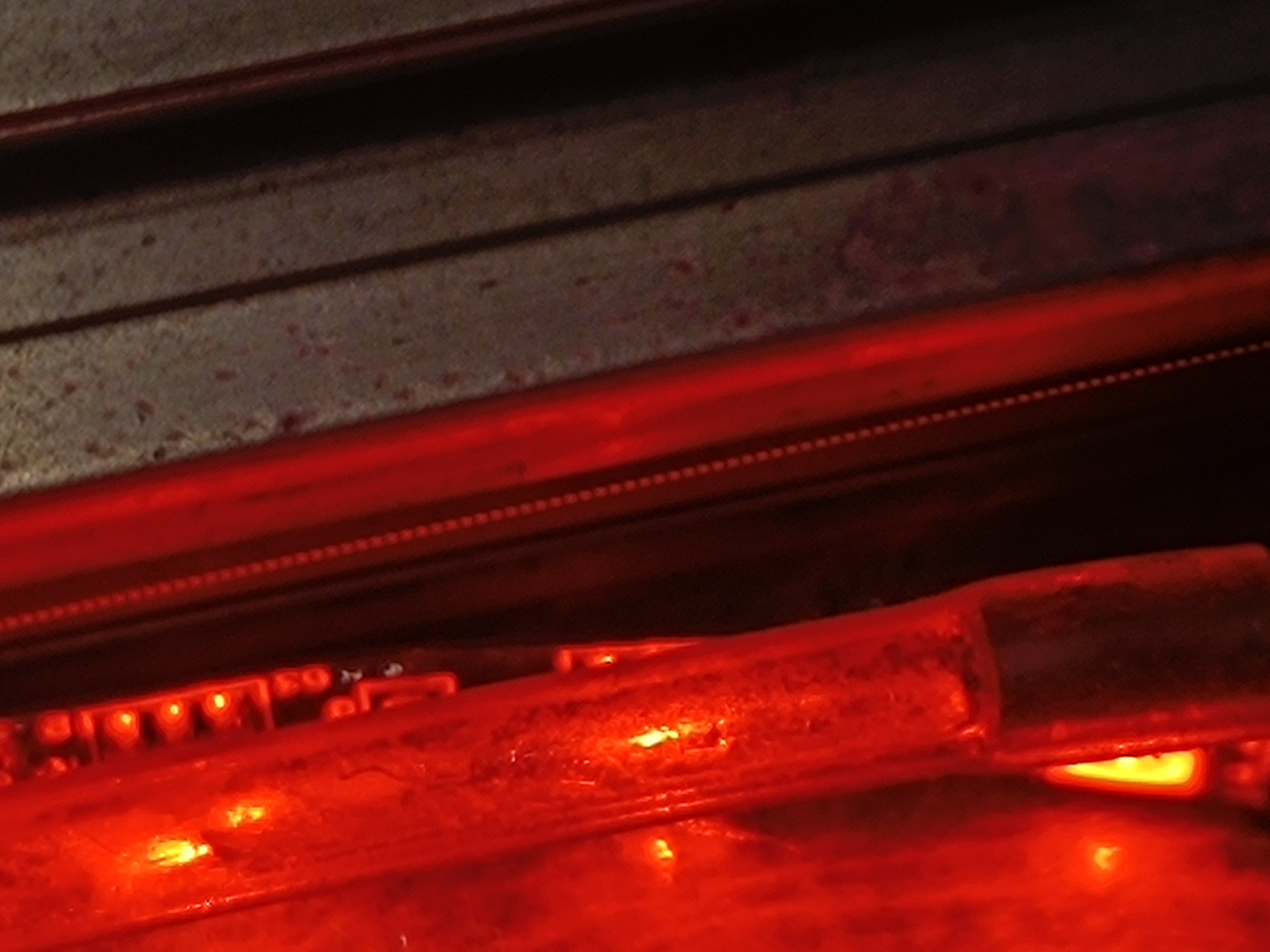
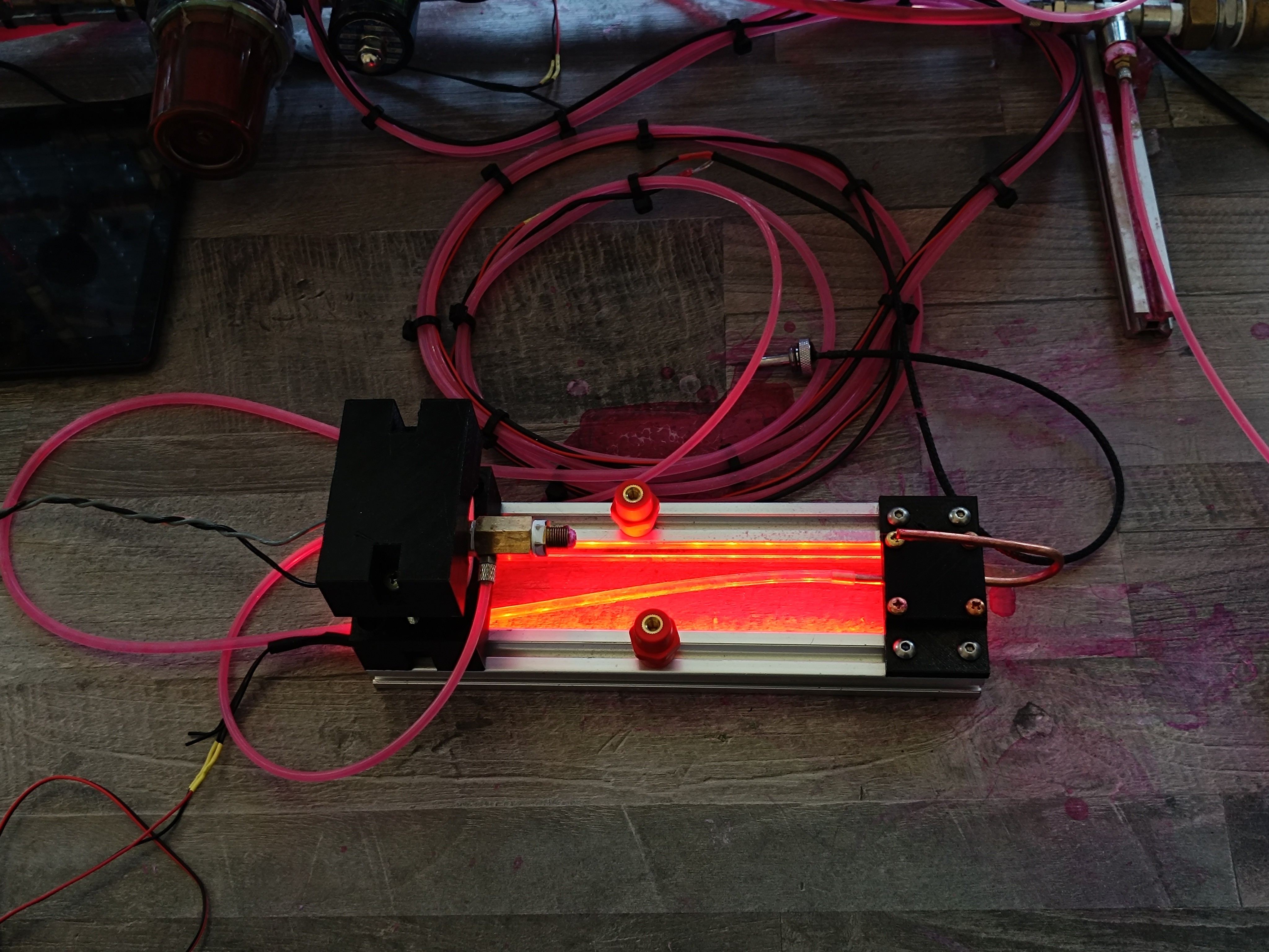
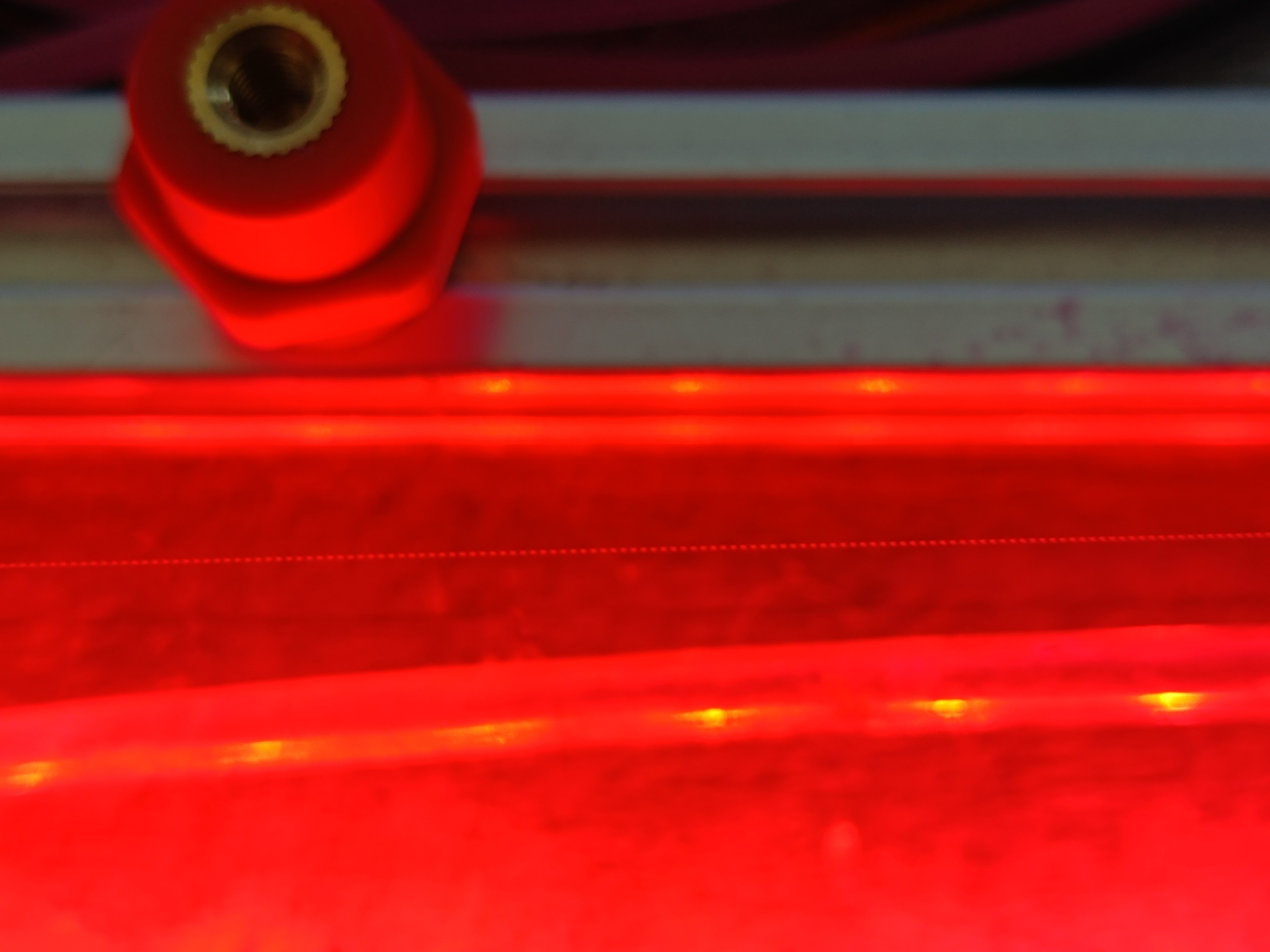
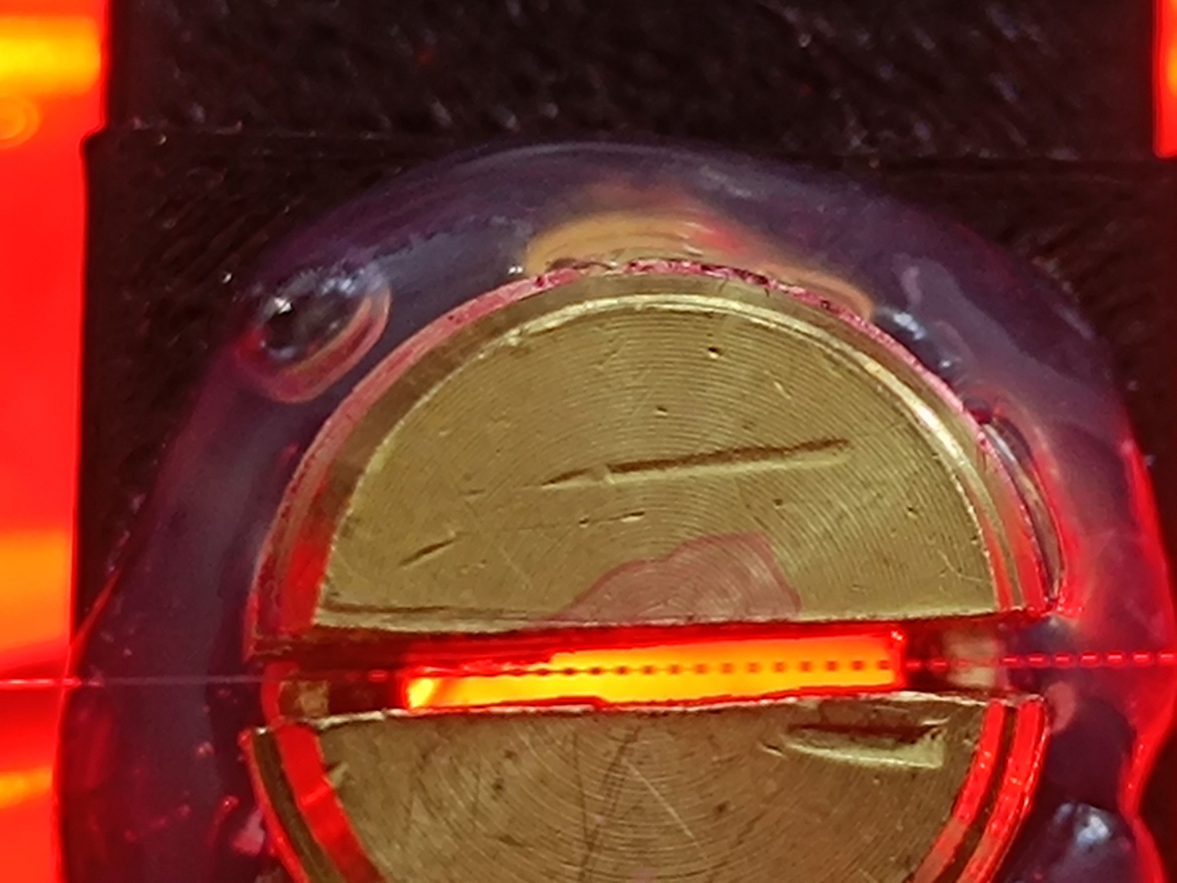
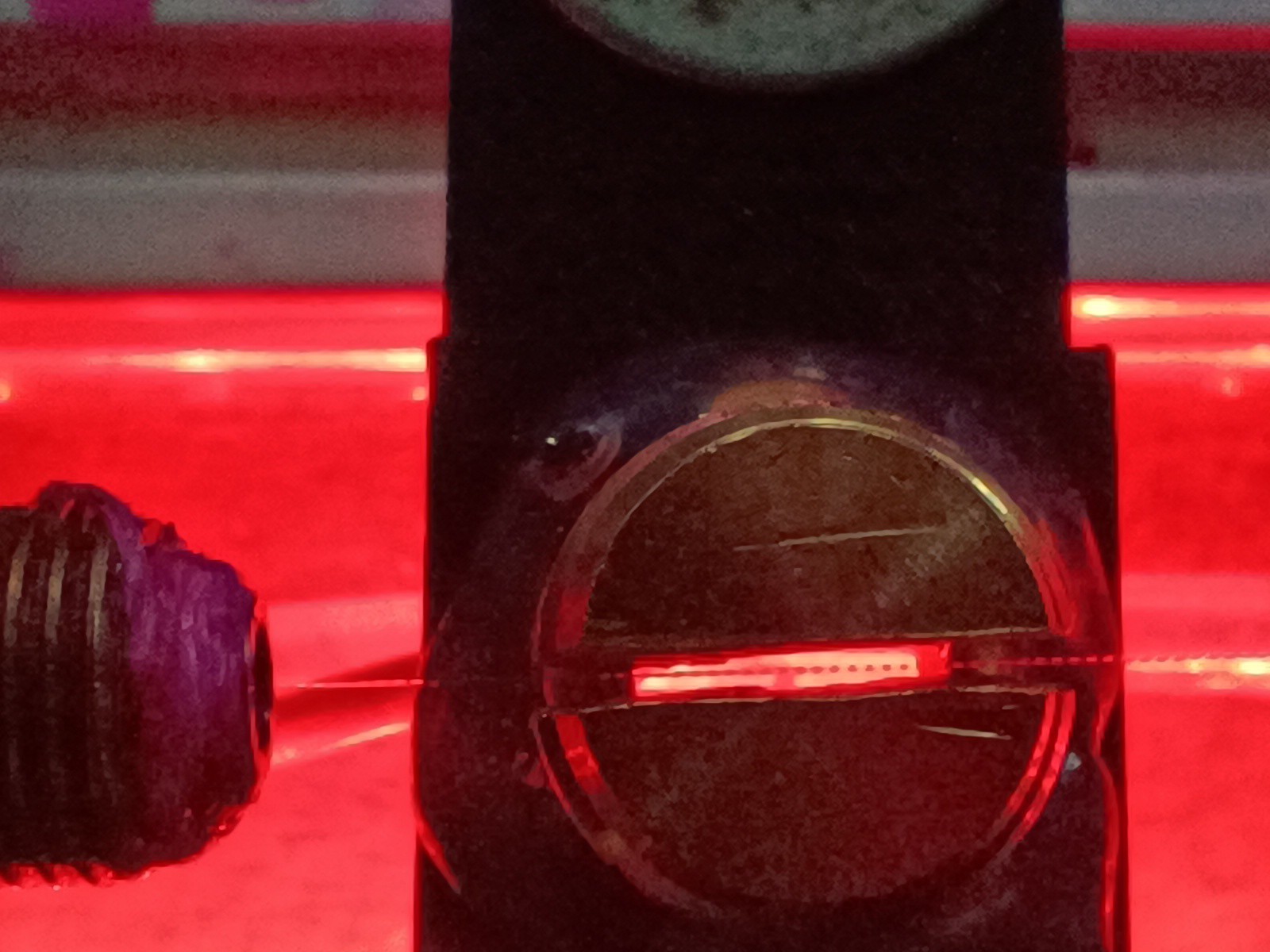
M10 Thread on the Ultrasonic Transducer, 1/8" on the Fitting with an inner M6 Thread. The 1/8" can be screwed into the M10 Fitting, because they have a similar Size. One Coupler Fitting and two 1/4" to 1/8" FittingsGround down 3D Printer Nozzles inside the rear and front Fitting, which act as Stoppes inside the Thread. The M6 Screws can be screwed against it to put pressure on the PTFE Tape that seals the Connection. The rear Fitting is sealed with a M6 Grub Screw and the front Fitting holds a 0.1mm M6 Sapphire Nozzle.0.1mm Sapphire Nozzle with M6 ThreadThe Sapphire Nozzle inside the Fitting4mm M5 CK Fitting for the Ink Line connected to the Coupling Fitting and bent 4mm Copper Pipe as Gutter TubeLED Strip as Strobe Light to make the Ink Drops visibleThe long LED Strip makes the Ink Drops visible across the whole Length of the PrintheadInk Drops visible up to the Gutter PipeLED Strip placed inside the Slot of the Aluminum ProfileInk Drops visiblePrinthead with Charge ElectrodeCharge Electrode made from a 1/4 Plug Fitting Breakup Point inside Charge Electrode
While testing to drive the piezo with a 40kHz sine wave at 12V with a small audio amplifier, I noticed that I had to reduce the amplification quite a lot to shift the breakup point away from the nozzle towards the charge electrode, so it seems like at least this part is working better, now.
With a way to make finer adjustments on the amplification and a way to control the amplification via software, it would be possible to move the breakup point back and forth over the distance between the nozzle and the gutter. This could be used to auto-tune the amplification to get the best charging result.
Currently, I'm doing this manually by changing the amplification while looking at the charge electrode to move the breakup point into the charge electrode.
After testing out how adjusting the piezo vibration strength changes the breakup distance, the next thing I want to test is how changing the piezo frequency changes the look of the stream breakup.
Ultimately, I want to find out how I can do a reliable Time of Flight test for measuring the ink stream velocity, which would be very useful since it depends on pressure, viscosity, and nozzle diameter and has to fit the used piezo frequency.
After taking a look at the charging and charge sensing, I also wanted to take a look at the drop formation. Both processes are crucial for building a working CIJ printer.
On many CIJ printers, a stack of 2 piezo rings is mounted on the nozzle to let it vibrate at a fixed frequency. Normally all parts are designed to work together within certain constraints:
The piezo frequency, stream/nozzle diameter, pressure, and viscosity need to fit well enough together to make a controlled breakup of the stream into equal-sized drops possible.
So much for the theory...
In reality, this seems to be a big challenge, and I'm constantly working to get it right at some point.
To learn more about the drop breakup, I was looking for a way to record it on camera.
Drops in Slow Motion
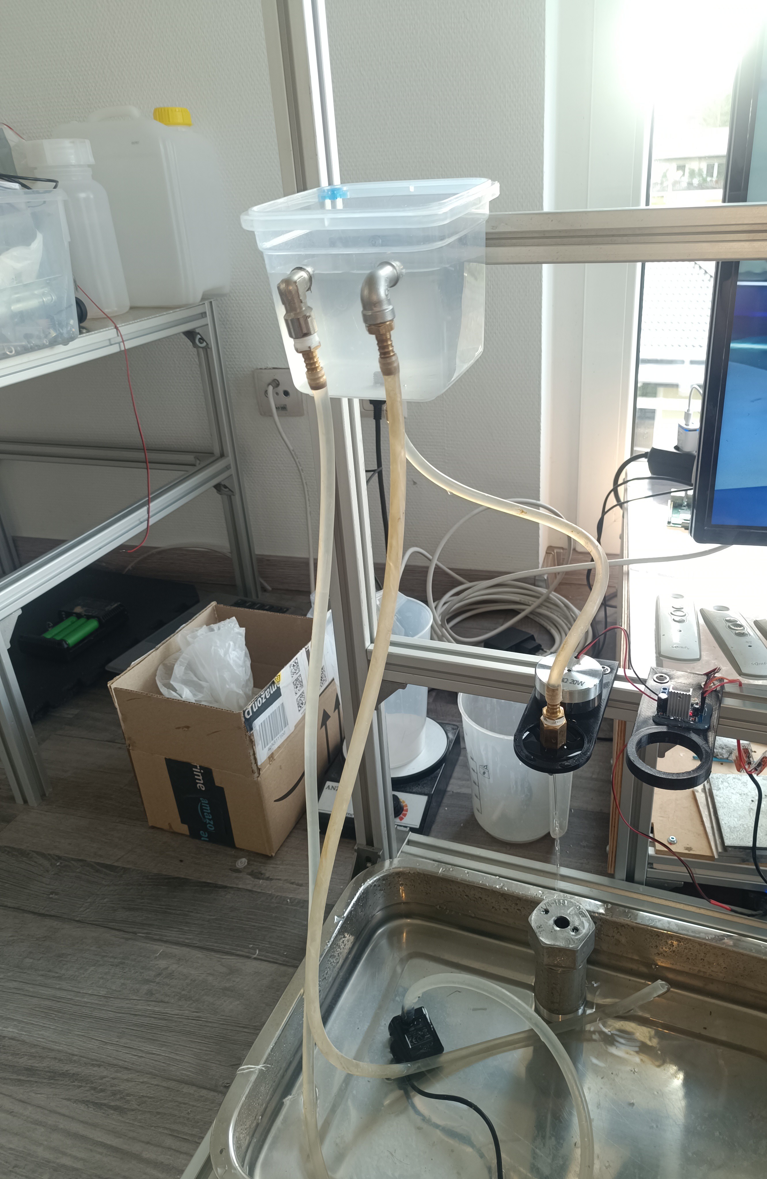
Changes to the previous Test Stand
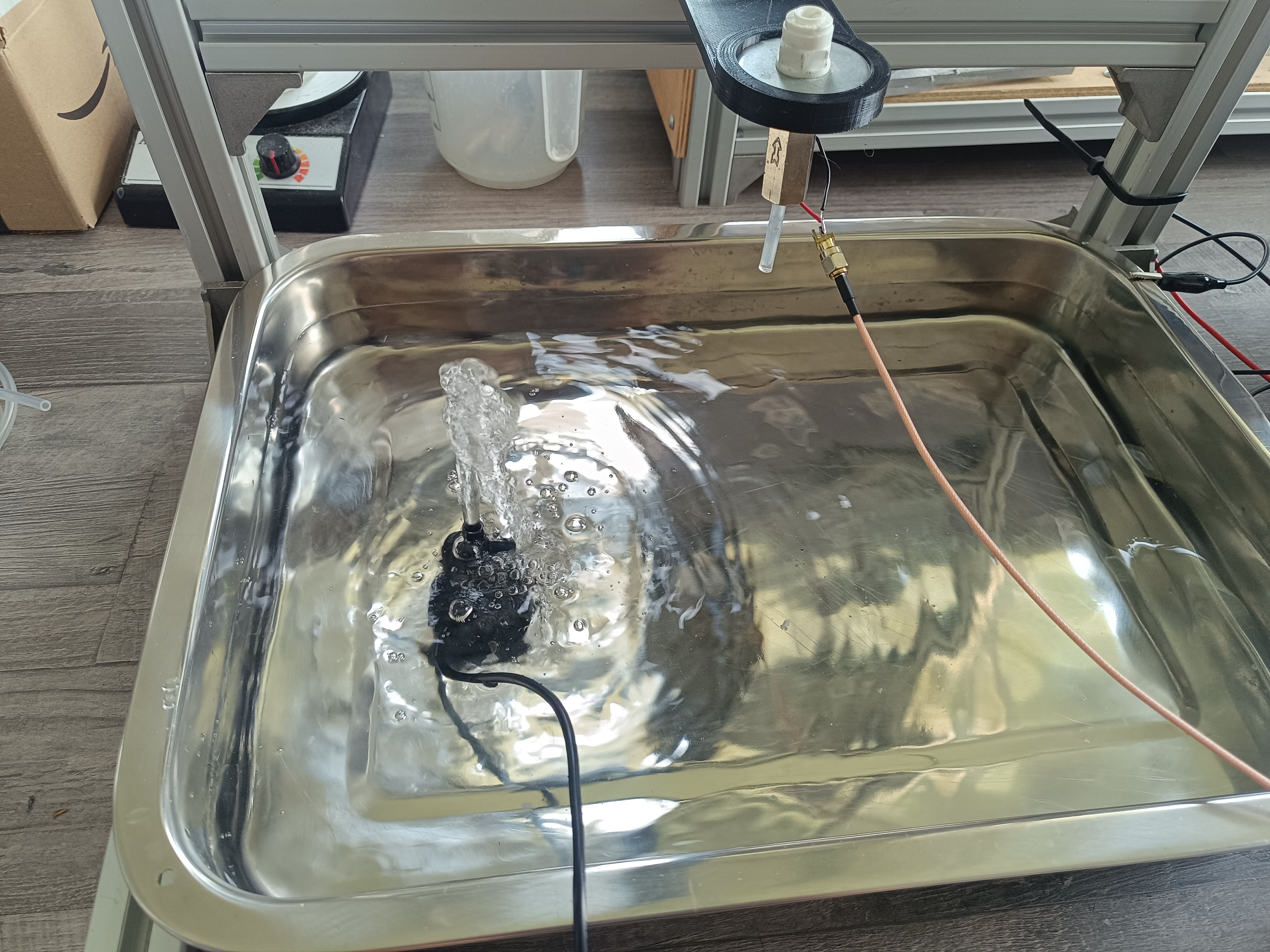
For recording the stream on camera, I replaced the 1 1/4 pipe tank with a pump to be able to record a continuous stream breaking into drops instead of drops dripping from a nozzle.
USB-powered Pump in Tap Water
The next step was to let the stream vibrate at a certain frequency to get an even, non-random breakup. To make recording easier, I wanted to use a larger stream so that no magnifying glass or microscope would be needed. Because of that, breaking the stream into droplets now requires a more powerful source of vibration.
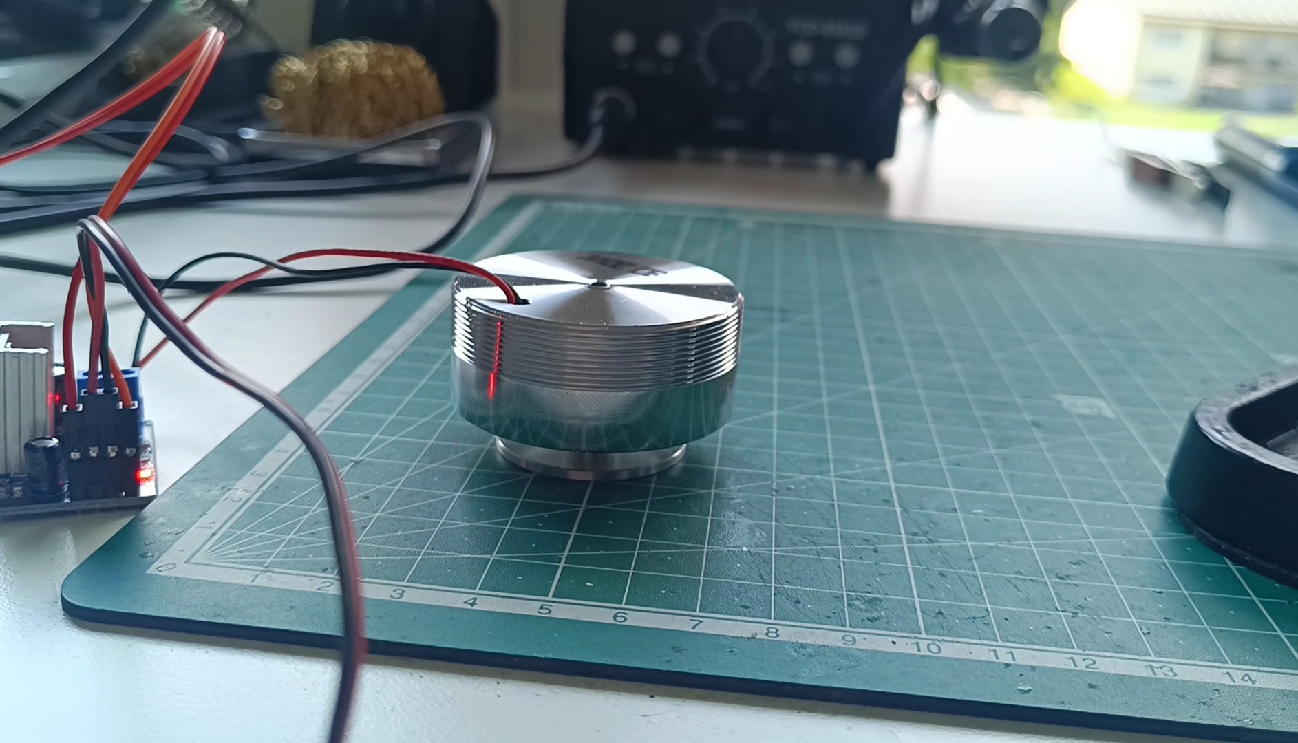
For this, I replaced the piezo with a vibration speaker, like the type of speaker that can play music via vibration when attached to the surface of a desk or wall.
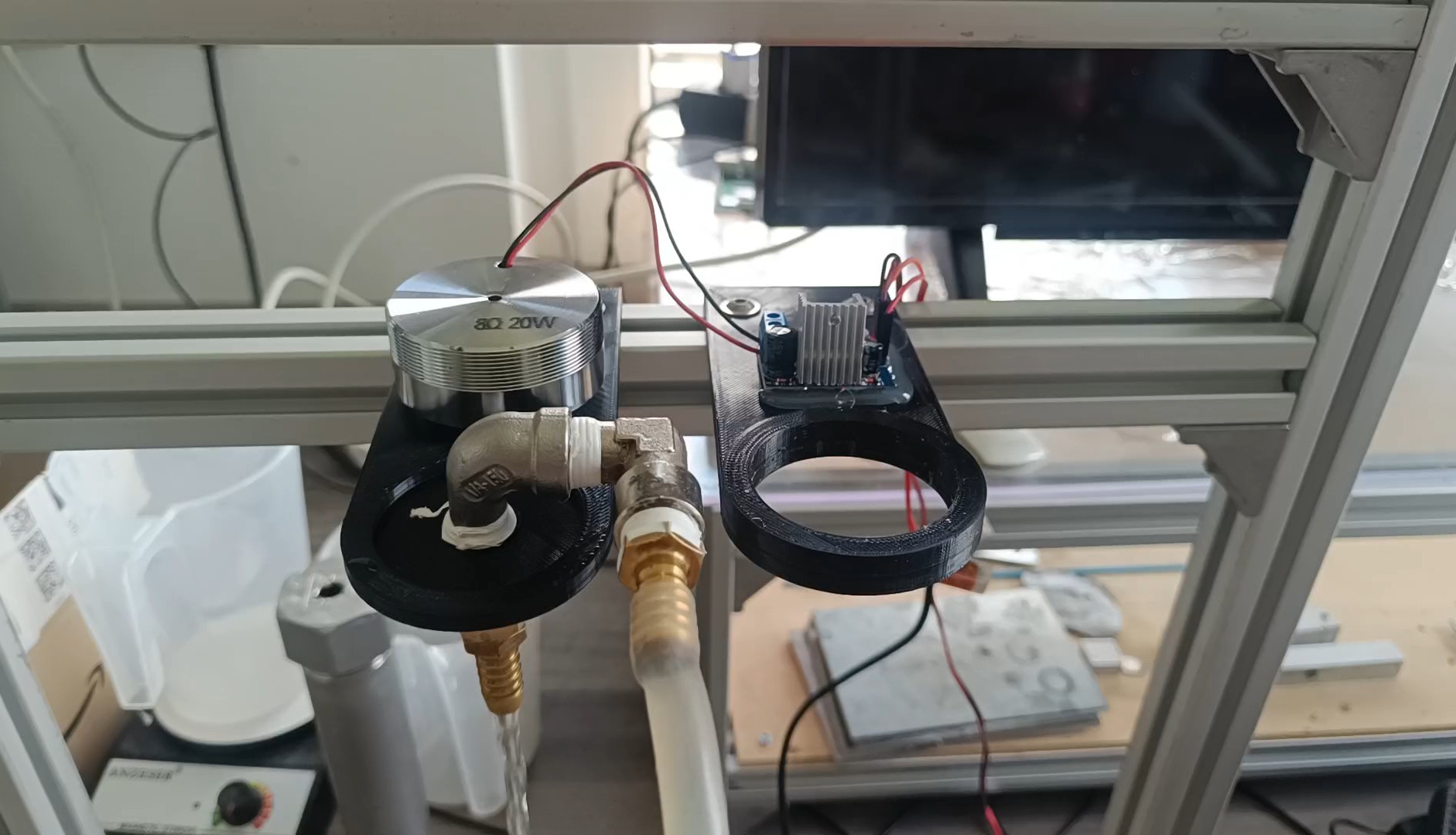
8R 20W Speaker and TDA2030 Amplifier
I got an 8R 20W vibration speaker and used a TDA2030 amplifier for driving it which I powered by 12V DC.
After verifying that the speaker could be used well for playing music through my desk, I attached it, together with the amplifier, to the test stand on which I also attached a 9mm hose fitting for using it as a nozzle, a silicone hose that was connected to the pump and some more fittings to hold everything in place.
Speaker and Amplifier mounted on the Test Stand
Now, I had two options for recording a slow-motion effect of the drop breakup:
- Using a strobe light matched with the speaker frequency.
- Matching the speaker frequency with the camera's shutter setting.
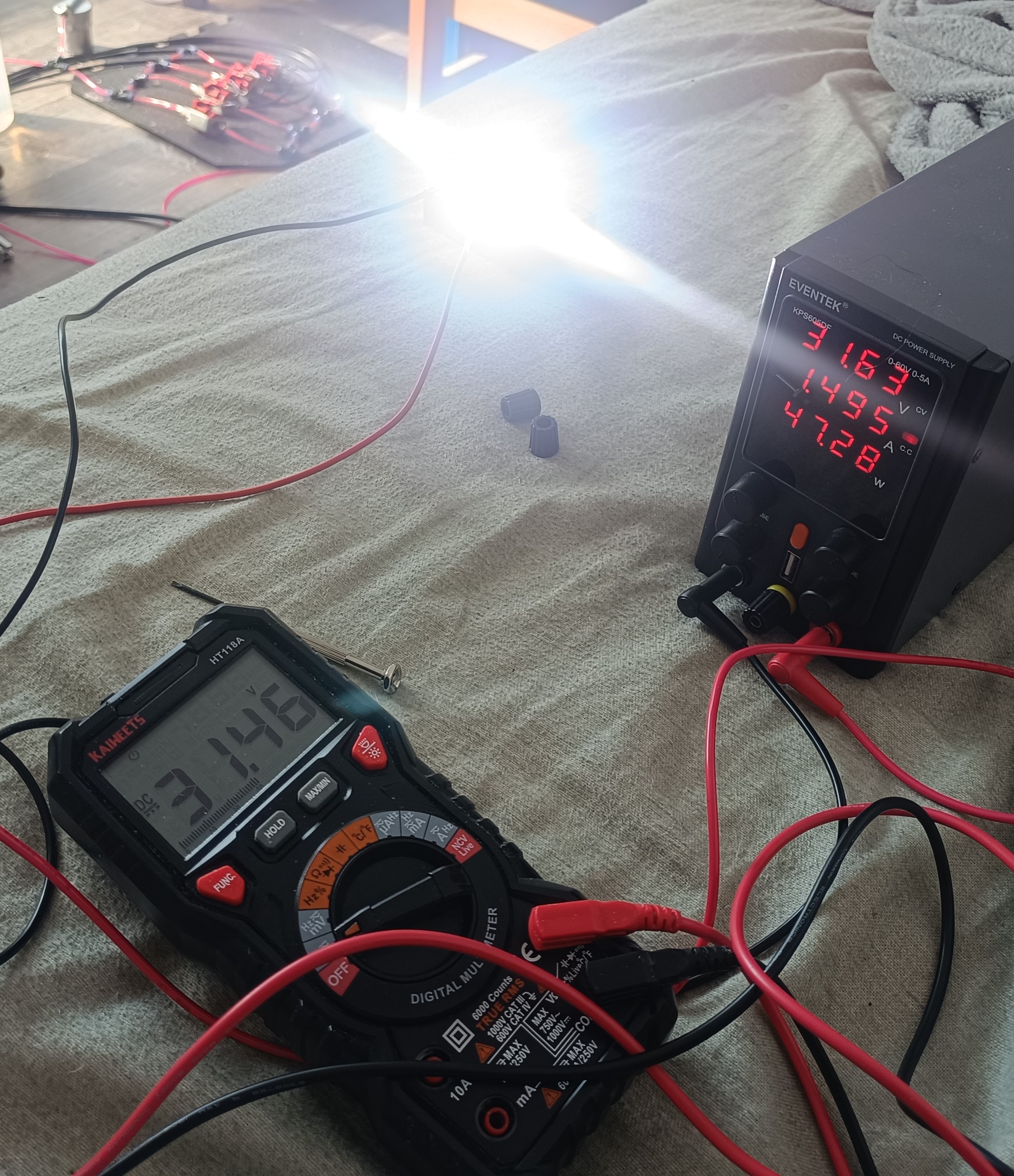
At first, I tried using the strobe light, so I got a 50W LED mounted on a heat sink and did a quick test run.
Then later, while waiting on the parts for building a strobe circuit, I also tested out using the other method and it worked well enough that I actually never tried using the strobe for recording.
50W LED on Heatsink
Maybe later, when a higher frequency is used again, the "camera shutter effect" will likely no longer work that well, and so a strobe light will be needed to make the breakup visible.
When I tested it at 50khz last year, I placed the stream in front of a 5mm LED which was also driven at 50khz.
So, it also was a strobe light - but just a small one.
50kHz Piezo Frequency and 50kHz LED Frequency
Testing with Water
First, I did a quick test where I set the speaker frequency just below 60Hz and the camera to 60fps, which made it look like the water would flow in reverse. The pipe with the cap in which the stream flows is used to reduce splatter.
Test with Water 58Hz and 60fps
Link to the video:
While there clearly was some effect visible it was not close to what I wanted.
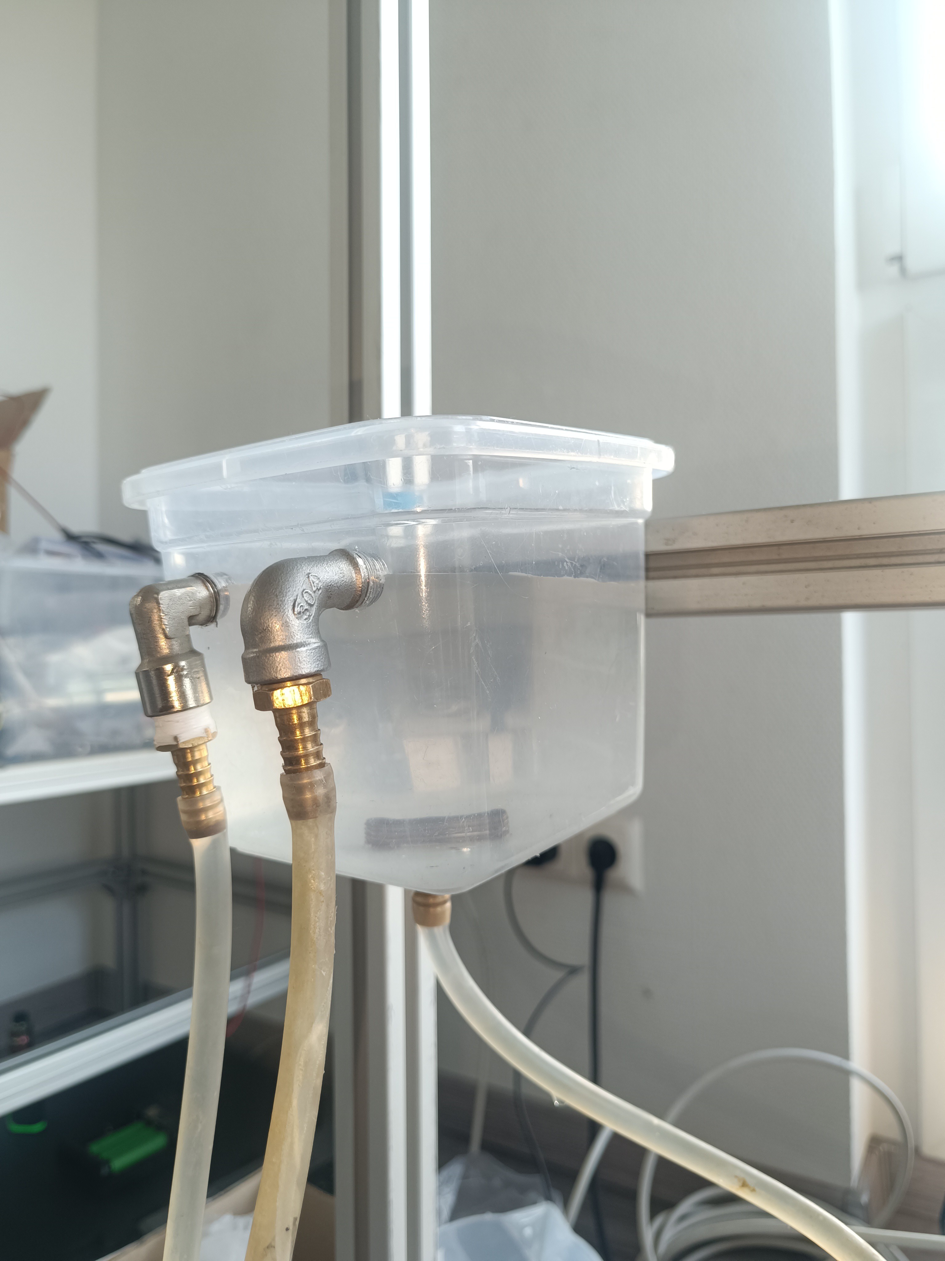
So, I tried using a container with an overflow hole to reduce possible vibration that the pump could transfer to the stream.
Overflow Box
This is how the test stand looked after the change:
Test Stand with Overflow Box
In addition to that, I also tried using a smaller nozzle (4mm OD / 2mm ID tube)
New Nozzle
With these changes, it started looking more like individual drops, but there was also a lot of splatter, and it seemed like there was a lot of water breaking out of the stream and falling not straight down.
A lot of Splatter
Link to the video:
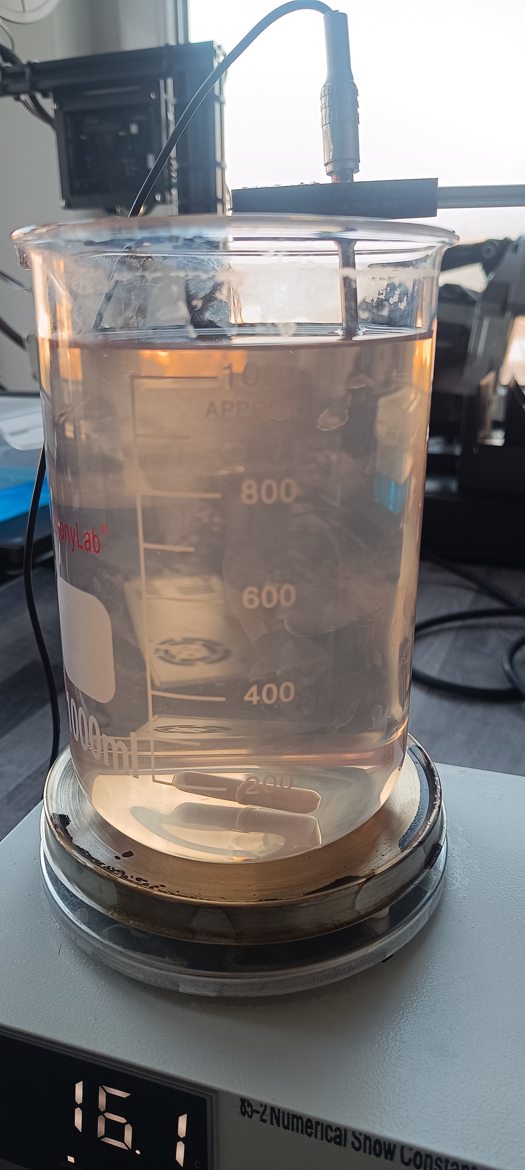
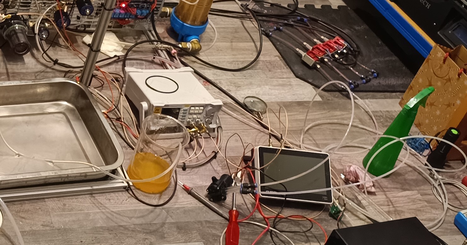
Testing with Glycerin
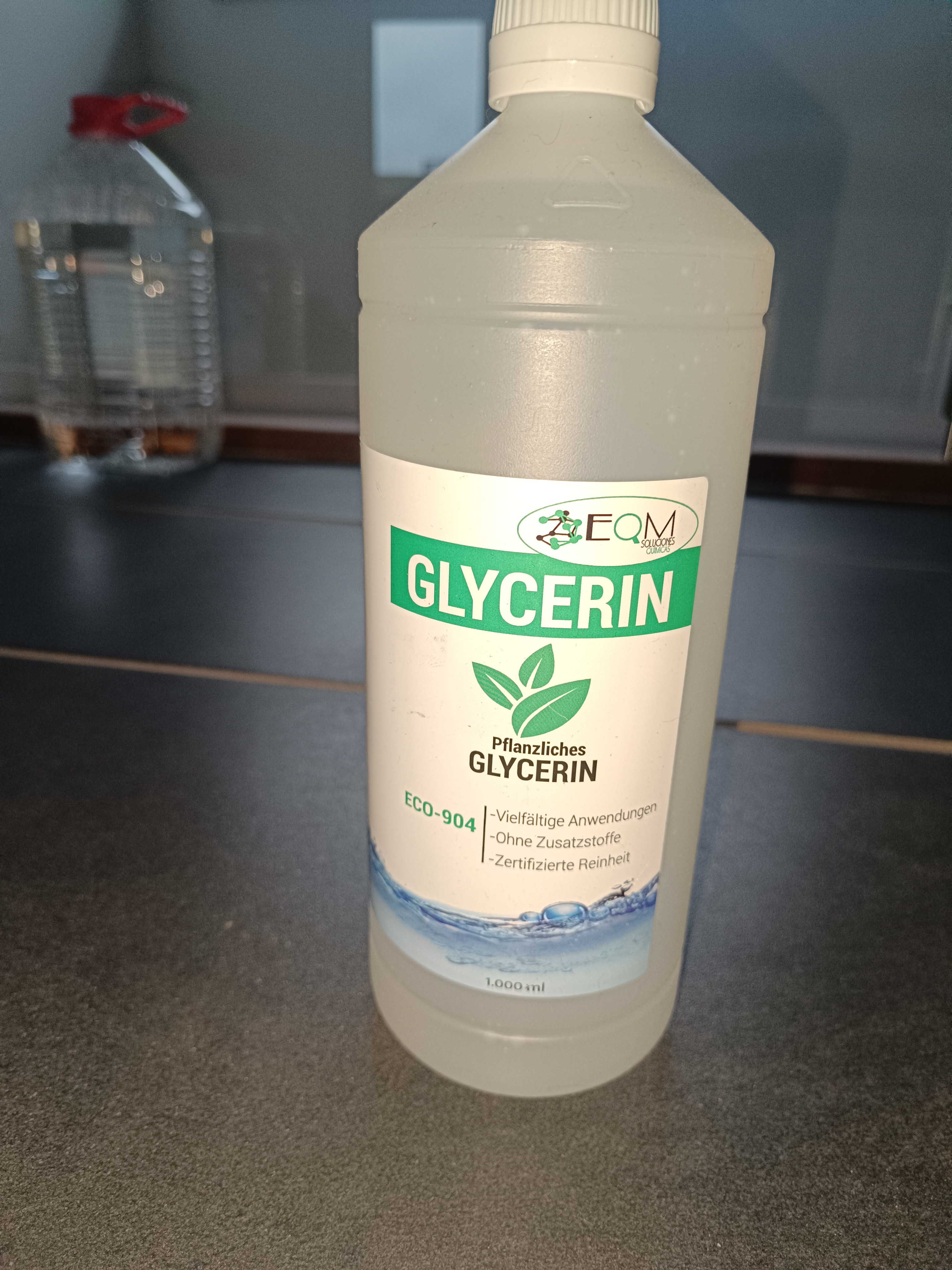
To get rid of the splattering, I wanted to try using a fluid with a higher viscosity so I ordered some bottles of glycerin.
Glycerin
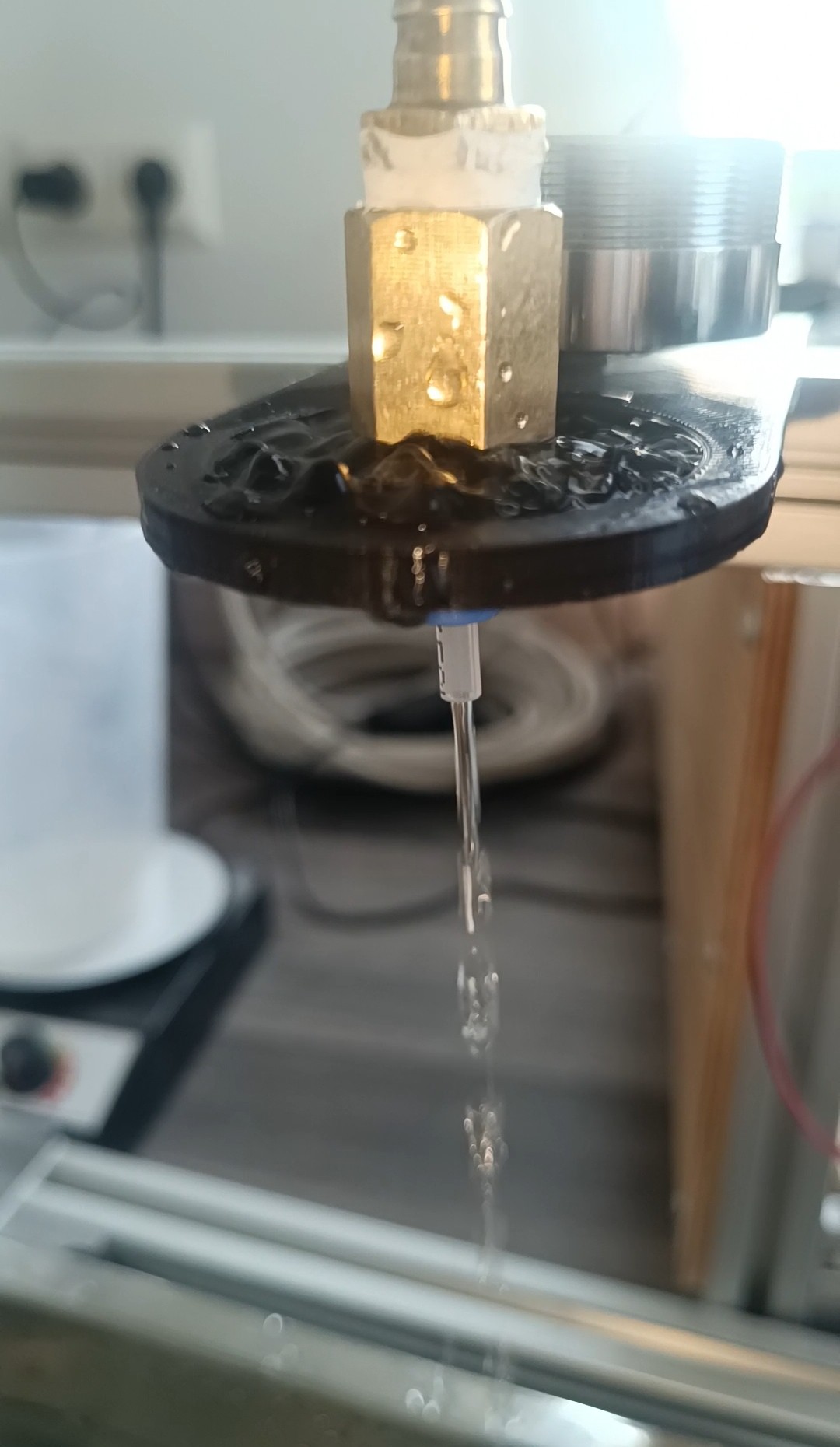
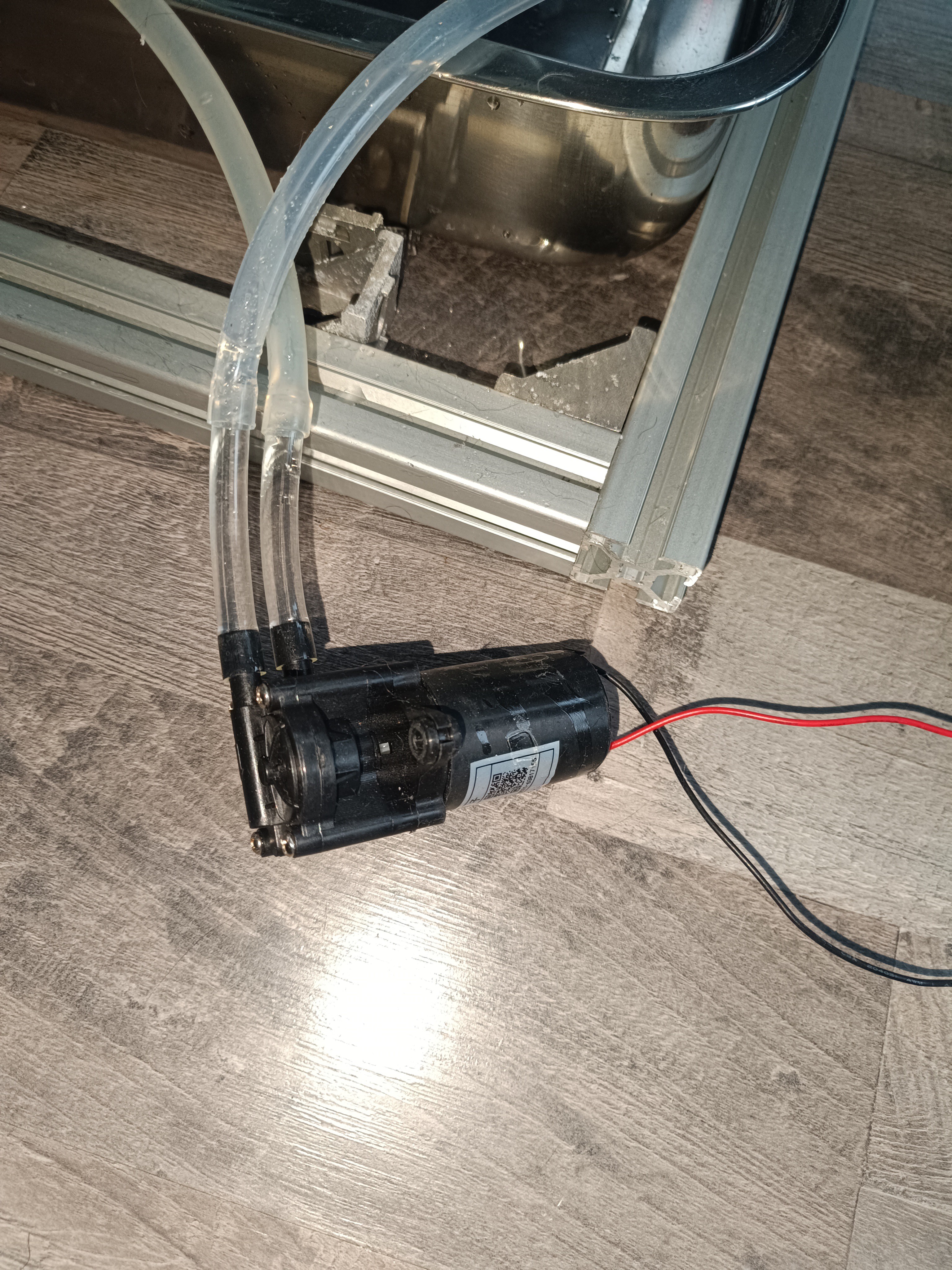
Because of a much higher viscosity than water, the brushless pump was no longer able to pump the fluid up to the overflow box so a gear pump was needed.
Gear Pump Glycerin
When using pure glycerin, the stream did not even break into droplets when it fell from the same height. l tried using a 5mm nozzle because there was no steady stream, but only drops with the 2mm nozzle.
5mm NozzlePure Glycerin doesn't break up into Drops when falling from the same Height
So, I tried adding some water and tried some mixtures. It turned out that the viscosity is better to control when adding water to glycerin instead of adding glycerin to water - the viscosity drops fast when a bit of water is added to glycerin.
By adding just a bit of water it was possible to use the 2mm nozzle again while the stream just started breaking into drops.
Glycerin with a Bit of Water
For the next test, I used a mixture ratio of Glycerin Water 2:1 and got a pretty nice result.
There was no more splattering from the stream and the "segments" looked much sharper and steady.
Glycerin Water 2:1
Link to the video:
Placing a lamp next to the stream made the individual segments even more visible.
Stream with Backlight
Individual Segments visible
Link to the video:
After that, I tried changing the exposure settings and was finally able to see individual drops falling down.
Drops
In the recordings, it is visible that the drops not only break up into one single drop but each drop is also followed by a smaller satellite droplet.
I often read that this could be problematic for the charging process, so I want to figure out what is causing it and how to deal with it in the future.
Satellite Droplets visible
Another recording with smaller satellite droplets:
Drop Breakup in Slow Motion
Some more videos:
Conclusion
It's relatively easy to make the drop breakup visible by using just a vibration speaker, amplifier, some backlight, a frequency generator app, and a phone camera set to 60fps in addition to the test stand.
The real challenge would be getting a perfect stable breakup on camera, that has no satellite drops.
I think the viscosity is a major factor here.
When I used pure water, the stream easily broke apart so that parts of the stream got deflected outwards and the separate drops were very wobbly.
When I used pure glycerin, the stream did not even break into drops.
When mixing both the breakup got much better, but not perfect since there were satellite drops visible.
Maybe, since viscosity is a fluid's resistance to flow, a higher viscosity makes it harder for the stream to break up, which prevents the stream from breaking up randomly so that it only breaks up to the vibration of the speaker when present.
The stream still breaks up on its own after some distance, but I think when the speaker's vibration is present, it is the major force that drives the breakup.
The "volume/power setting" of the speaker is also important. When set too low, the stream doesn't break up into drops; when set too high, the breakup starts getting unstable until it disappears. I tried setting the volume to 0 and started increasing it until I got a nice-looking breakup.
From what I have read, the Plateau - Rayleigh Instability is the effect that causes the stream to break up into drops:
So, I'm optimistic that reading more about the topic will help to understand what the key factors of the breakup are for ultimately getting a perfect stream breakup without satellite drops that can be charged and deflected for CIJ printing.
Update:
After reading a bit about the Plateau-Rayleigh Instability, I want to build a setup for measuring the jet velocity, next.
I'm also currently replacing the push in fittings and PU tube with CK fittings and PE tube, because the seals in the fittings get leaky over time and the PU tube seems to get dissolved slowly by the ethanol.
Great thanks to Robert who helps me a lot with this project and thank you for your interest :)
Proof of Concept: Over the past months, I worked on a few things, and I just found the time to write about them.
The first thing I worked on was a stand for charging drops and testing if I could sense the charge somehow to start the work on the charging system from scratch.
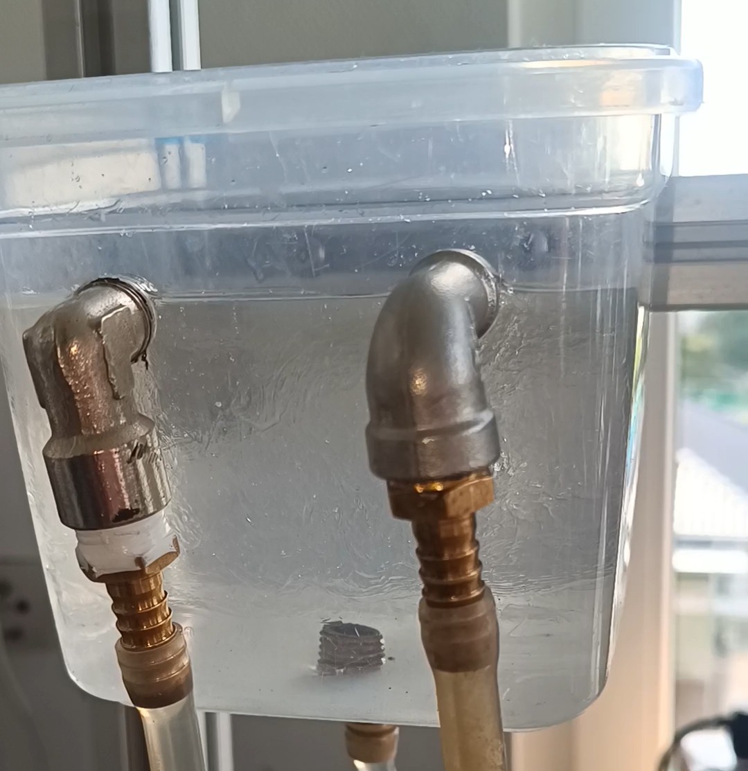
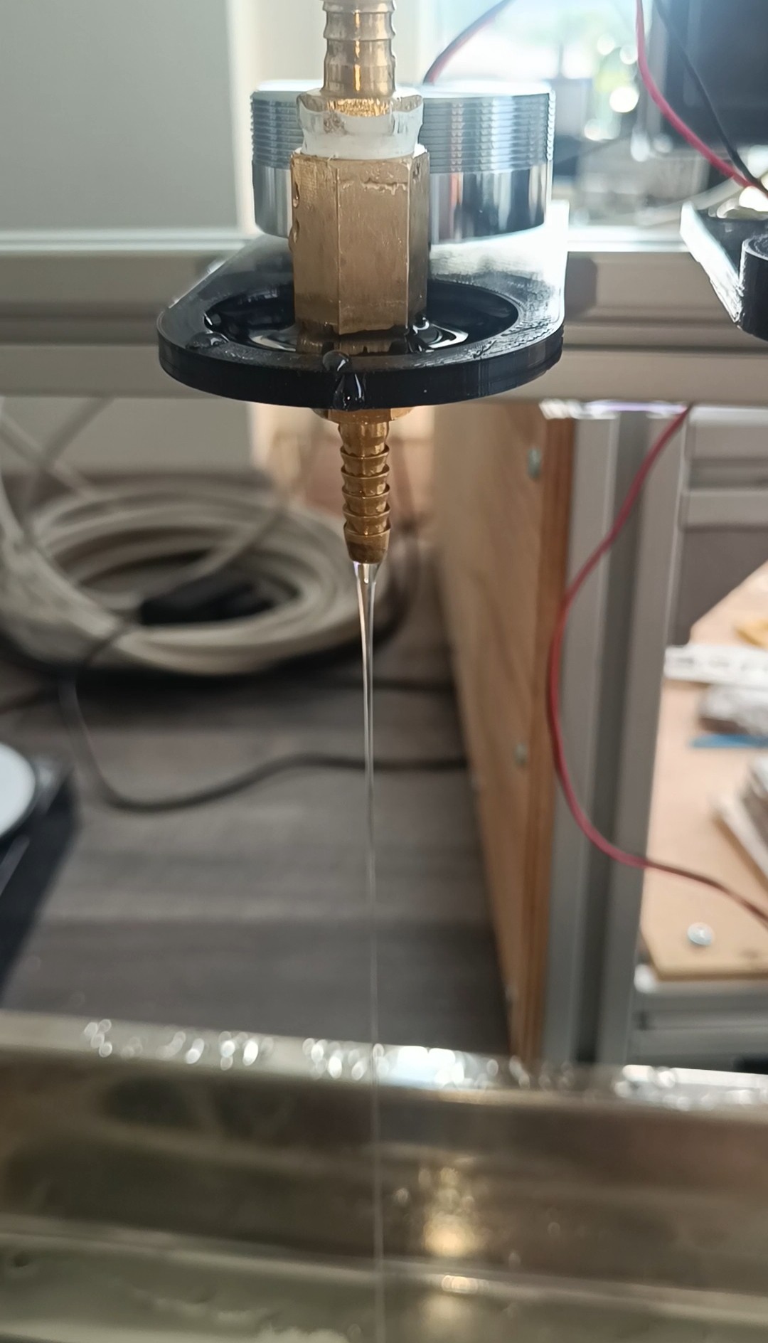
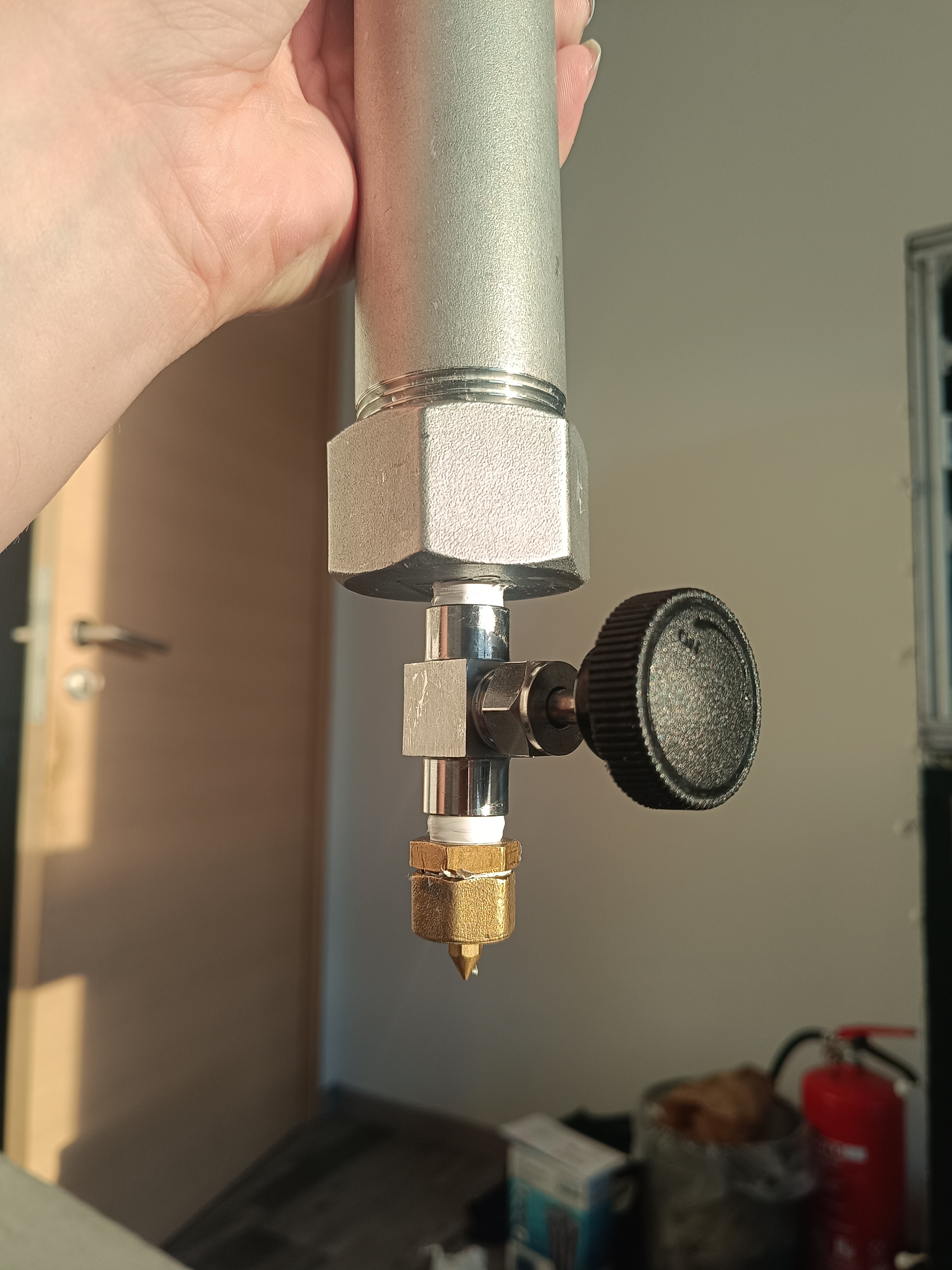
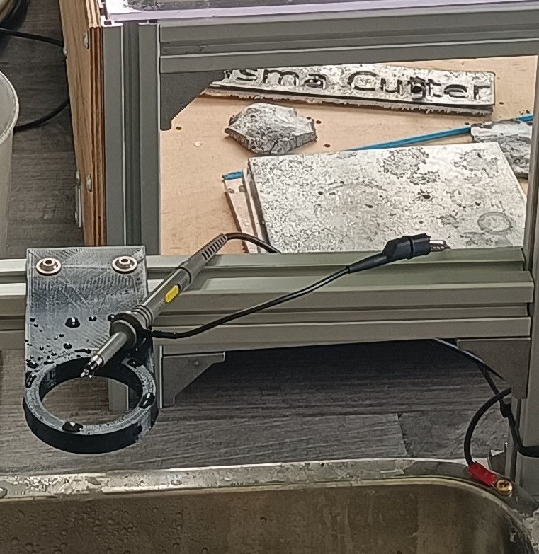
I started by building a pipe with a valve and a 1mm nozzle that I could fill with water, which I could let drop out slowly by slightly opening the valve.
1 1/4 Pipe with Valve and Nozzle
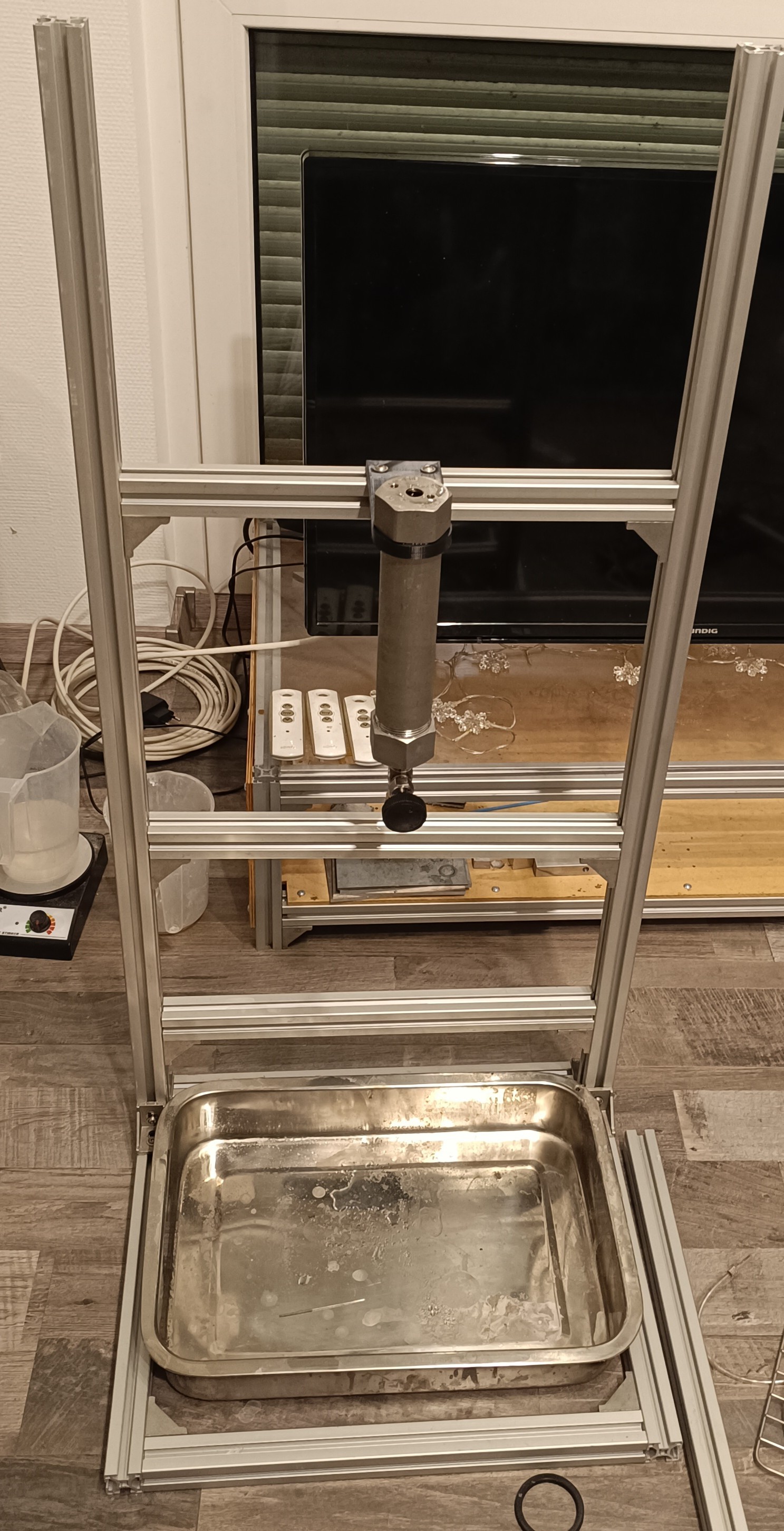
Then I built a test stand out of two 1m 3030 profiles and a few shorter pieces for attaching the pipe on it with 3D printed mounting brackets.
Test Stand with Drop Pipe
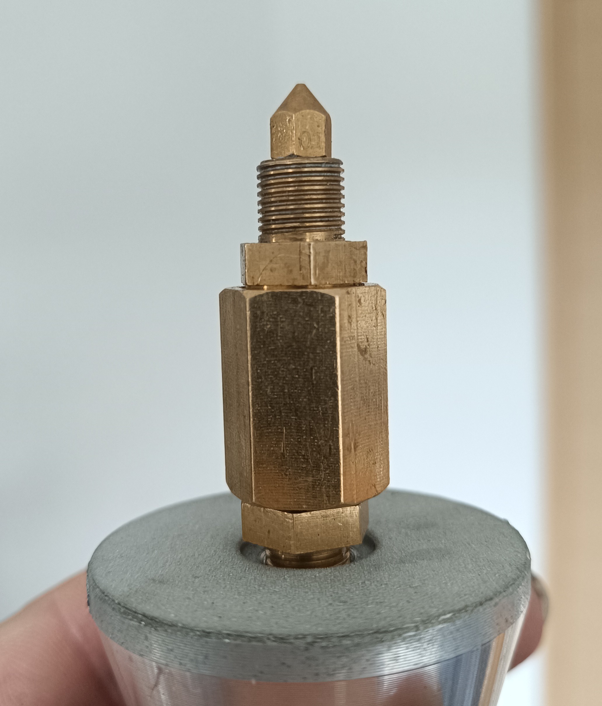
For charging the drops I soldered a 1.5mm² wire onto a 1/4 inch brass fitting and mounted the fitting on another 3D printed bracket.
Charge Fitting
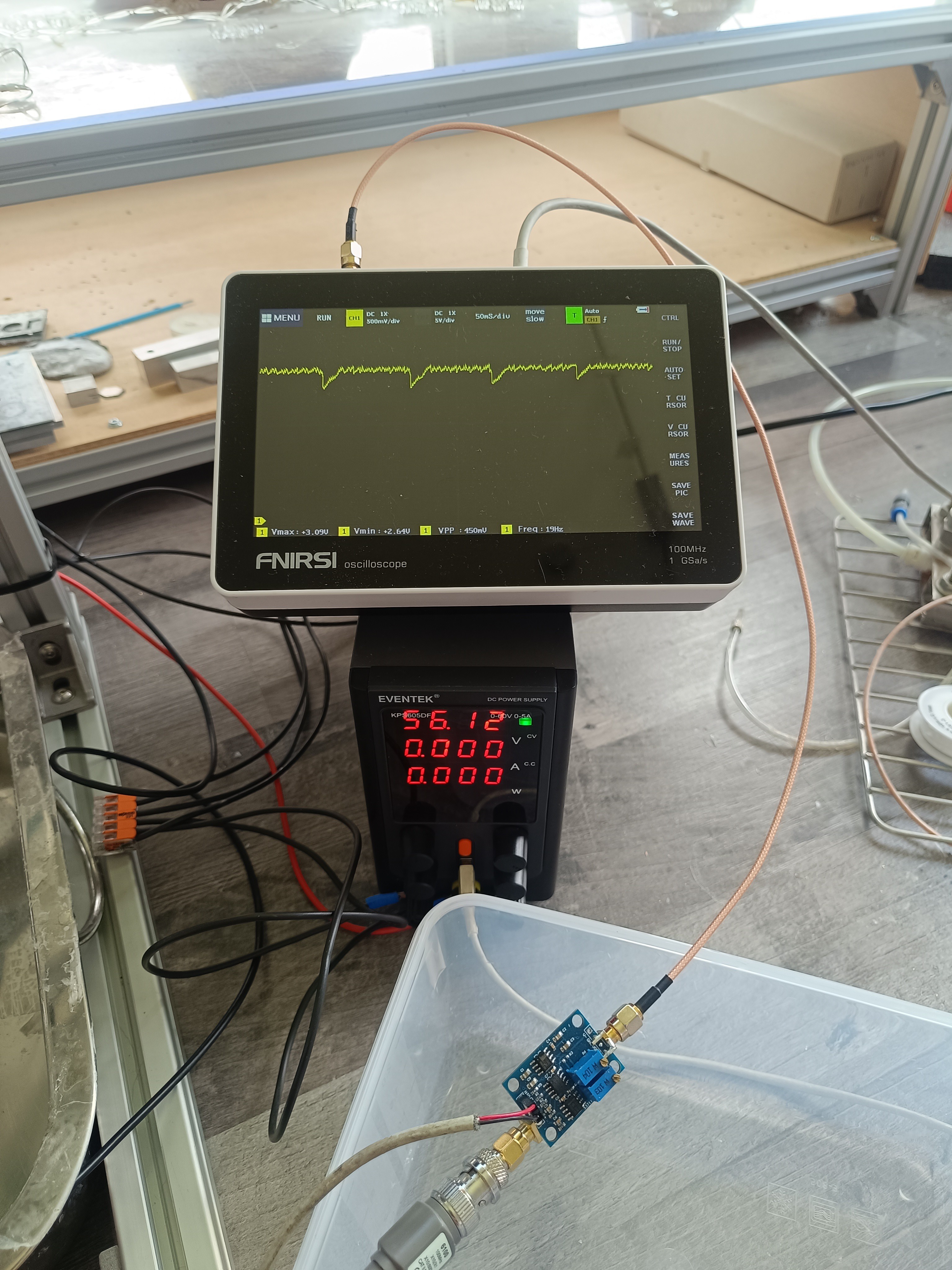
I used 56V DC for charging the drop while it passed through the fitting without touching it.
The drops get charged at the moment they break loose from the stream, so I placed the brass fitting closer to the nozzle.
Nozzle inside Charge Fitting
At first, I tried to sense the charge on the drop with a piece of copper mesh in a funnel connected to an oscilloscope probe which was connected to an amplifier, but because I could sense nothing but the 50Hz mains frequency with it, I tried using just the tip of the oscilloscope probe for sensing the drop.
Copper Mesh
I guess the mesh acted as an antenna and picked up noise from the environment.
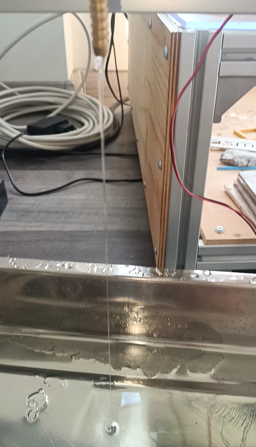
Drops falling on Oscilloscope Probe
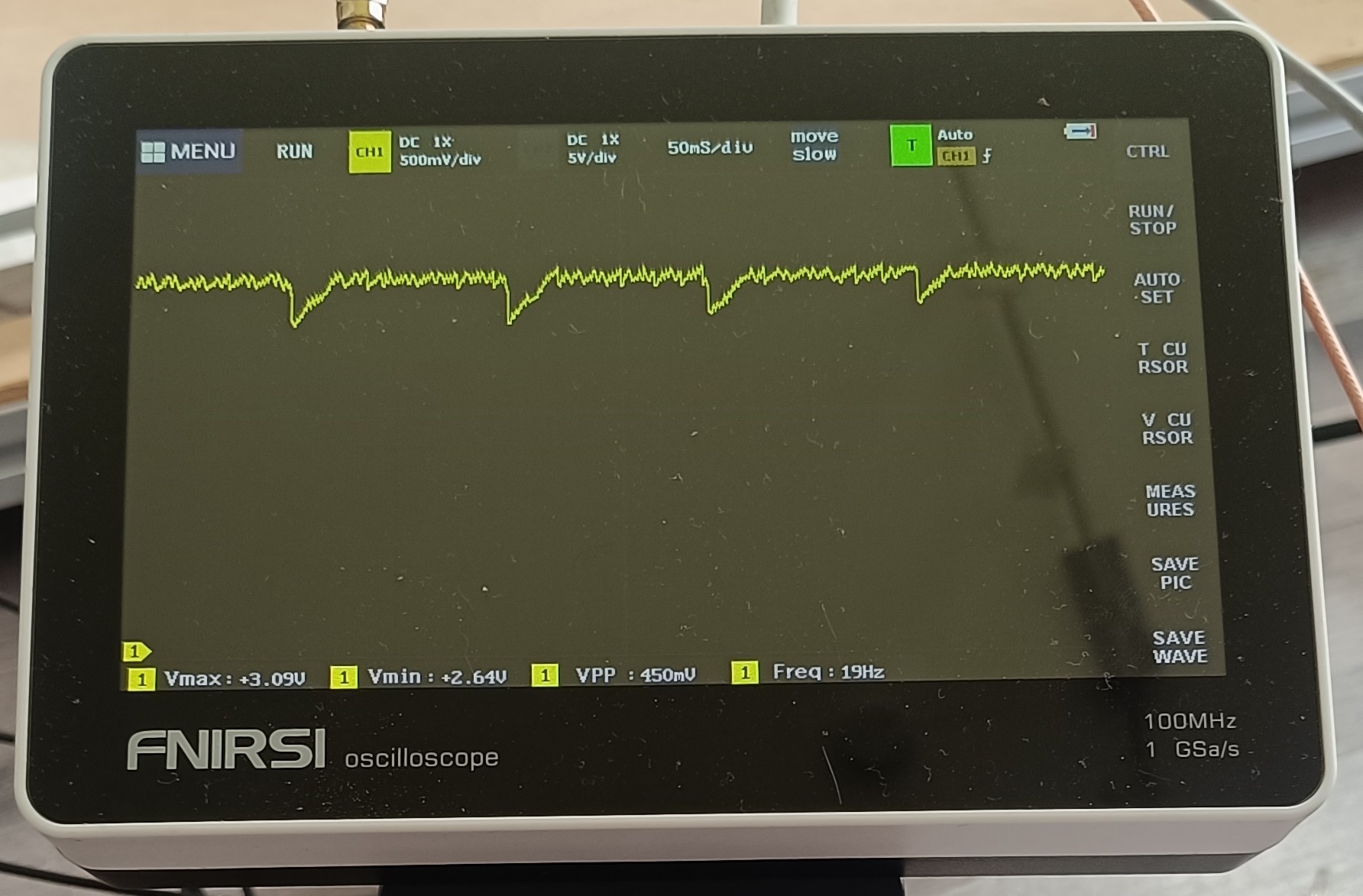
With the probe connected to the amplifier and oscilloscope, it was possible to sense the charged drops when they hit the probe's tip.
Drops visible on Oscilloscope
It was also possible to sense the frequency at which the drops hit the probe.
Sensed Voltage and Frequency
Here is a picture of the setup.
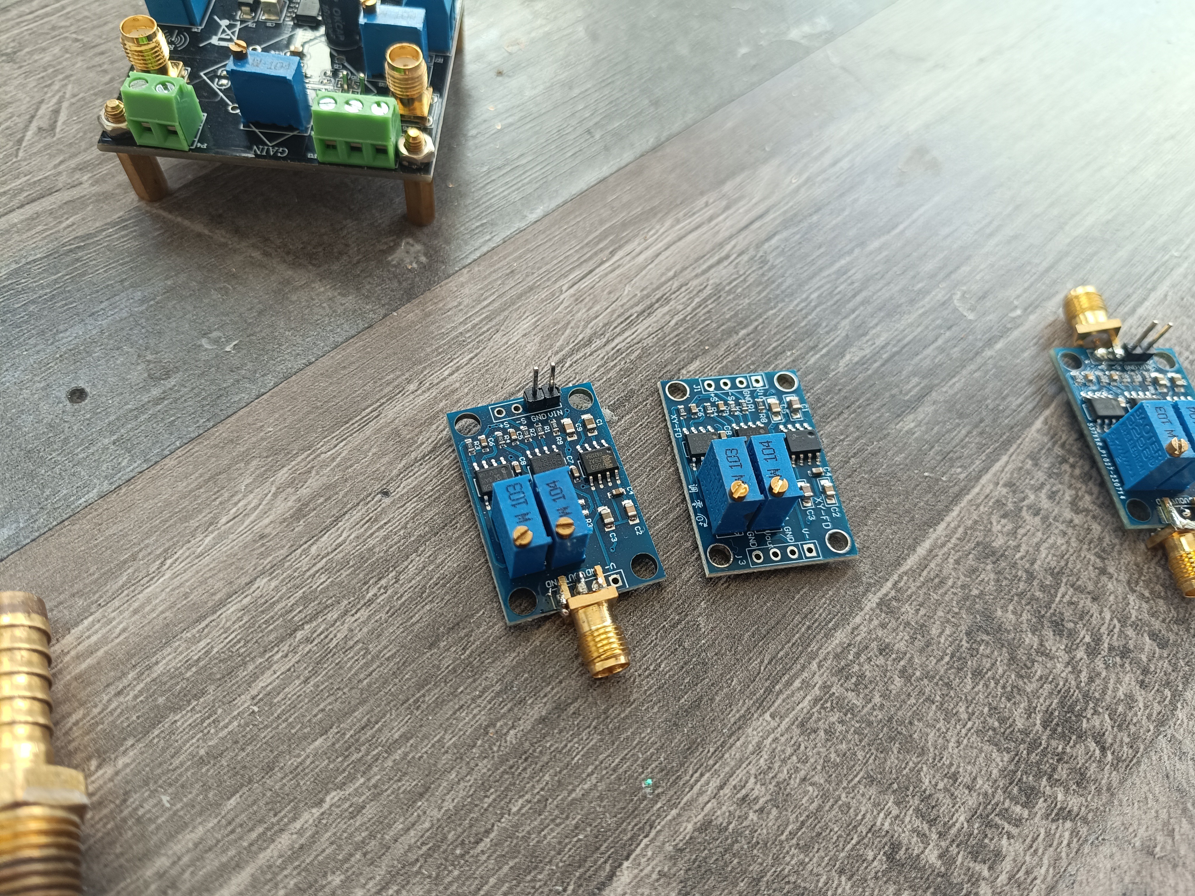
I used the AD620 instrumental amplifier module for testing. It was needed to connect the S- input to GND to get a reading out of it.
Oscilloscope, Power Supply and Amplifier
The power supply's ground was connected to the ground clip of the oscilloscope probe, the 1 1/4 pipe, the drip tray, and the frame of the stand.
Probe connected to Power Supply Ground
Based on the test result, it seemed like it would work to sense charged water drops with it, and to prove that it wasn't just luck, I tested 5 of the same amplifiers in the same configuration.
I also tried turning the power supply off and reducing the charging voltage, which was visible on the oscilloscope. Without a voltage, there was nothing sensed when the drop hit the probe, and a lower charging voltage resulted in a lower amplitude of the sensed signal.
When the tip of the probe was connected to the ground of the probe by water, there was also no reading visible on the oscilloscope.
AD620 Amplifier ModulesThe result was the same on all 5 AD620 amplifiers I tested.
5 Amplifier Modules - All of them worked
A picture of the whole setup
Test Stand
After finding out that it was possible to sense charged water drops, I wanted to try building a proper sense electrode to replace the oscilloscope probe.
Building a Sense Electrode:
What I want to build here is the gutter sensor of a CIJ Printer.
Many CIJ Printers have such a sensor, and while some models also have a senseless phase detection sensor (sometimes in addition to the gutter sensor), I want to focus on the type of sensor that is located in the gutter for now.
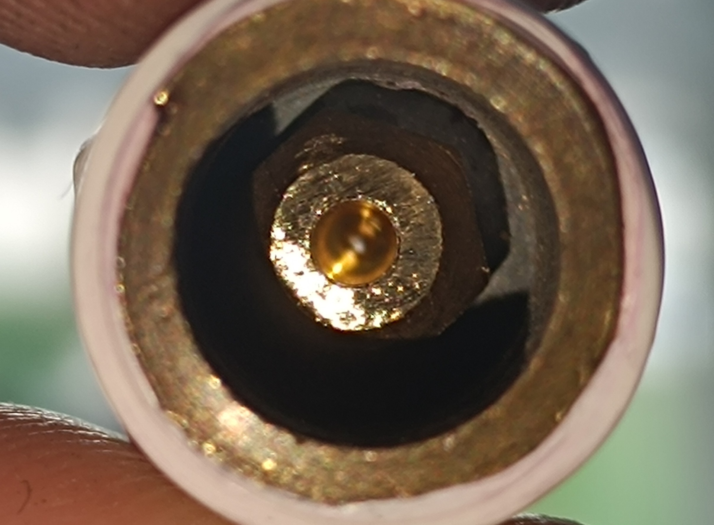
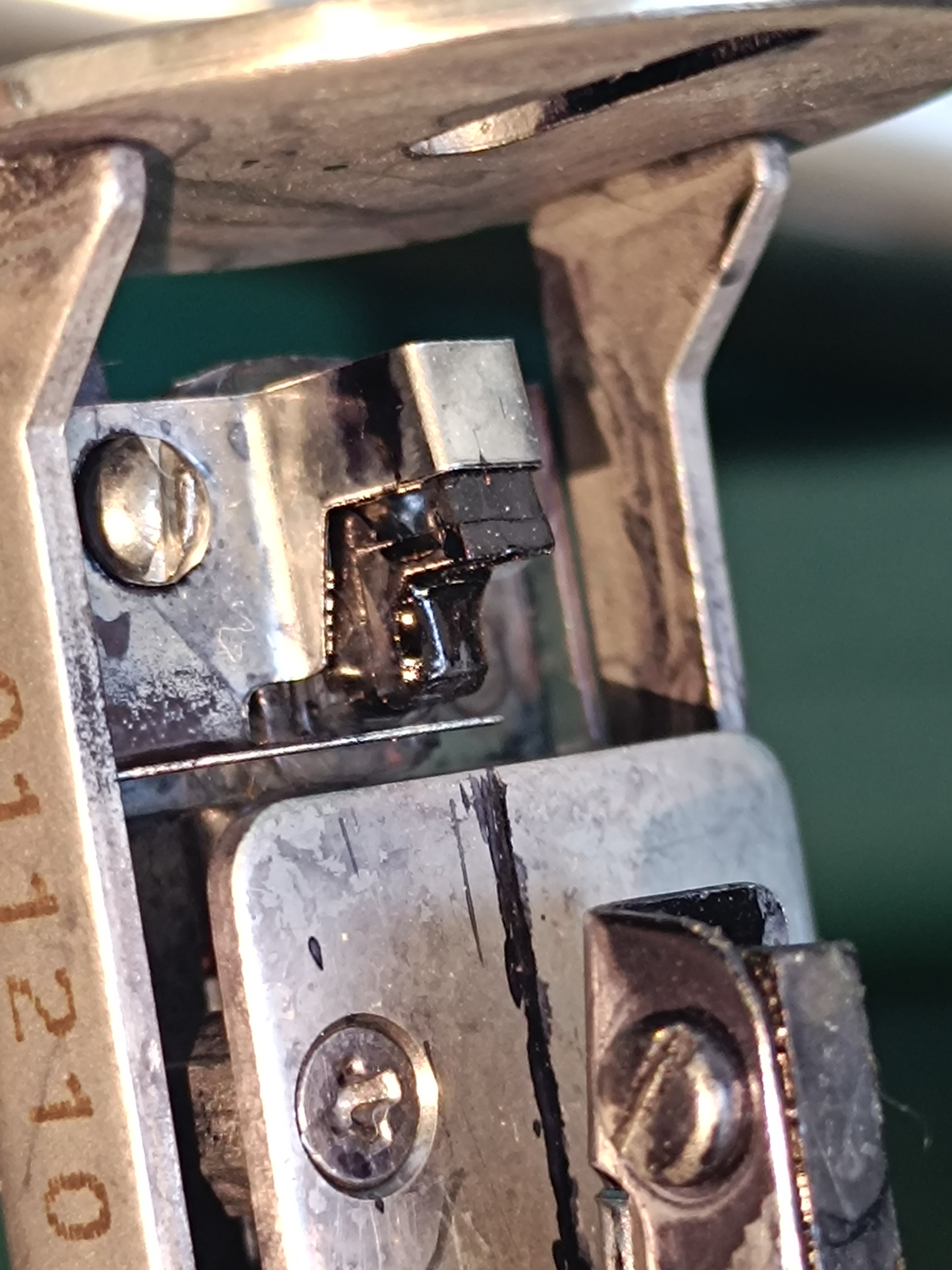
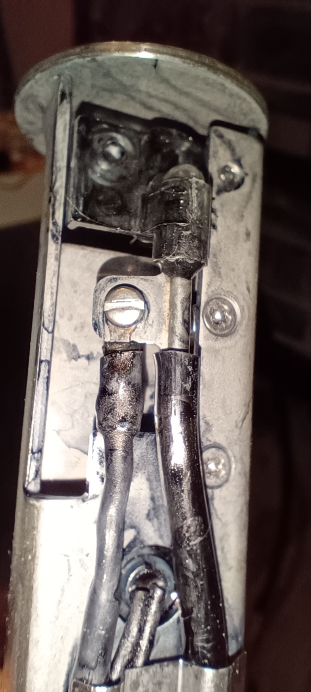
On the printhead of an older CIJ printer model, the gutter sensor looks like this from the top:
Shielded Ink Return Block
The metal on the upper part is connected to the printhead ground and covers the plastic block from the top and sides.
Shielded Ink Return Block
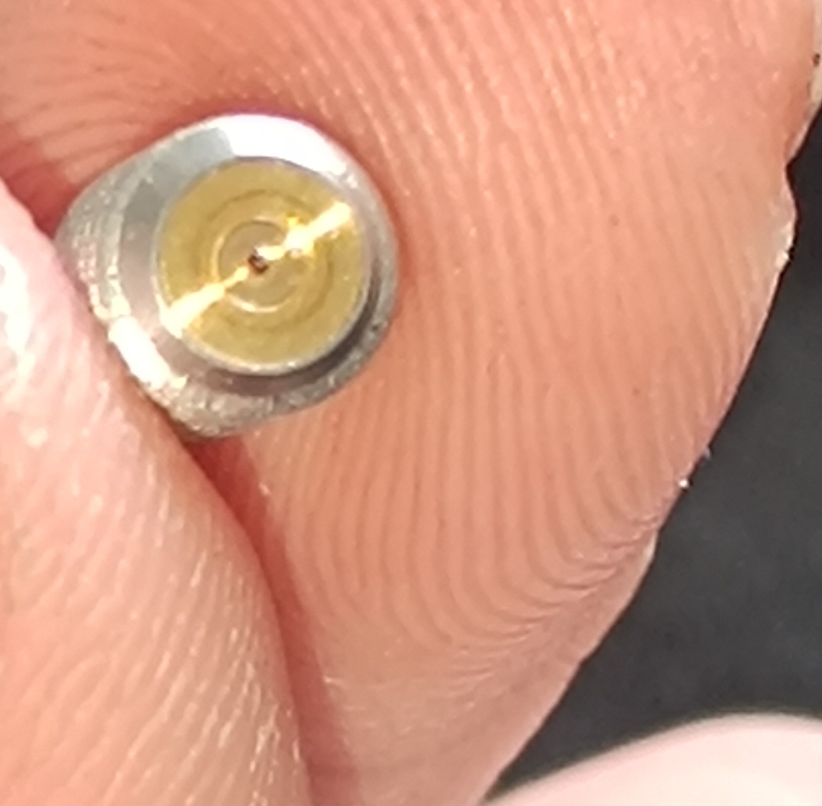
From the bottom, it looks like this:
A small metal pipe with a wire connected is attached to the plastic block.
Sense Pipe and Shielded Cable
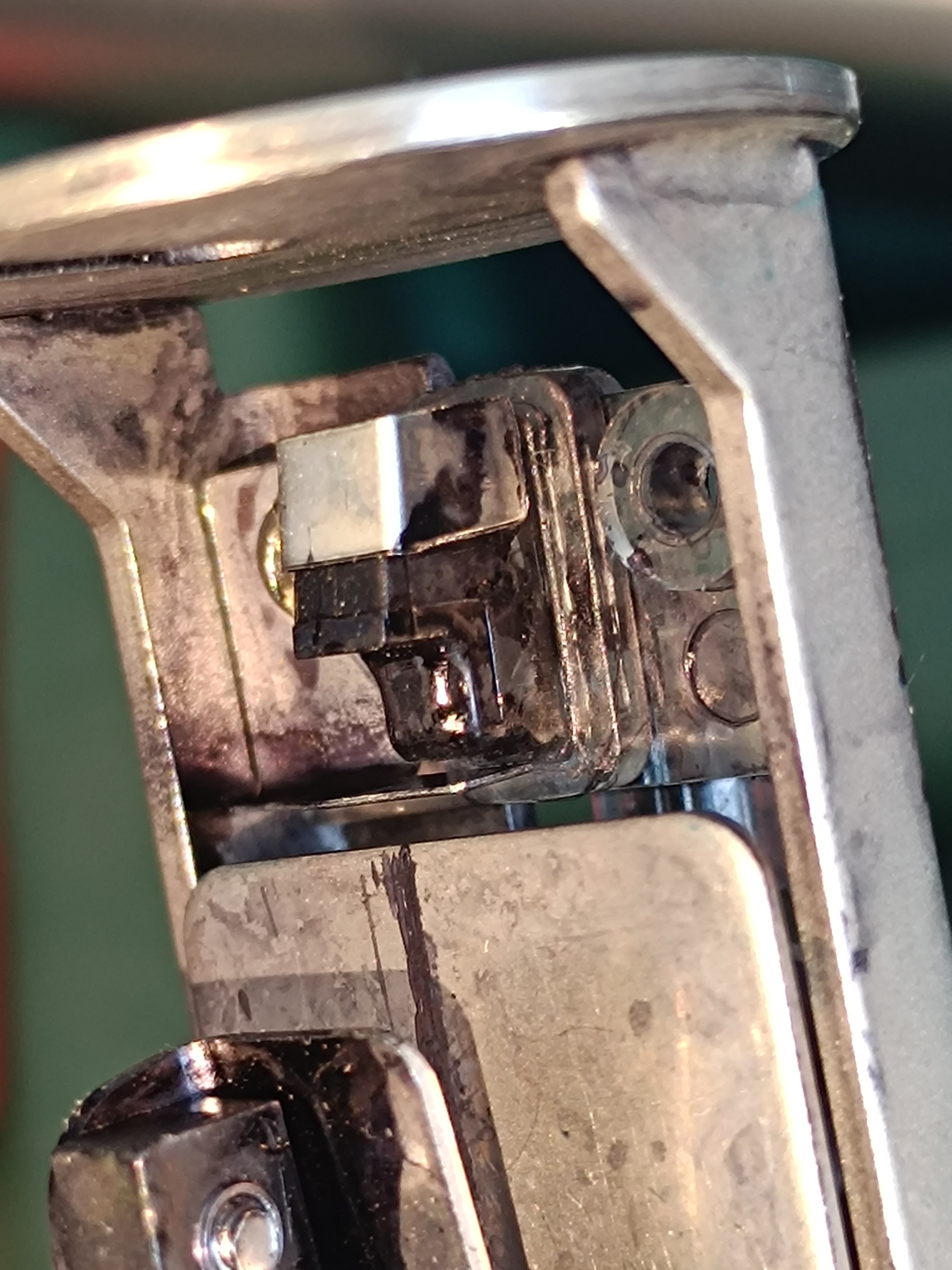
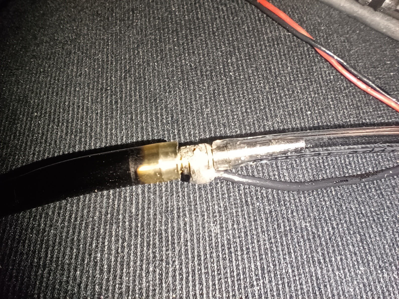
Further down the tube, there is a small metal pipe which also has a wire connected to it. Here is a picture of it with the shrink tubing removed while I was replacing the return line:
Pipe Connection to Reference Ground
The cable that goes to the gutter sensor and about 10cm further down to the small pipe is a 3-core cable.
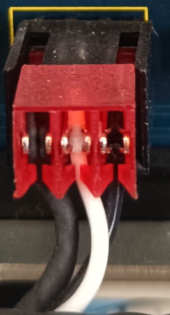
Here is the connection of the cable on the printer's control board:
On the left, there is the shield connection; in the middle, there is the sense connection, and on the right, there is a ground connection.
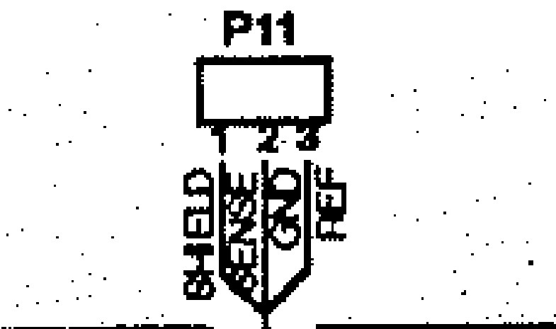
On the wiring plan, it looks like this:
As far as I can tell, the shield is only connected to the control board and has no connection to the printhead.
The purpose of the sensor on this printer is to do two tests:
- Detecting if an ink stream is present
- Finding out which of the possible four phase shift settings that can be applied to the charge signal give the best feedback signal.
At the moment of writing this, I'm not completely sure why the ground reference is connected to the small pipe in the return line.
My guess would be that it needs a ground reference as close to the return block as possible which is not directly connected to the frame of the printhead.
Normally, there is a vacuum applied to the return line, which sucks the ink back into the printer when the ink stream hits the return block.
When I did my tests with the oscilloscope probe, I couldn't get any reading when the tip was shorted to the ground by water, but maybe the vacuum helps to prevent the buildup of a conductive path from the ground to the sensing pipe or it isn't a problem for the sense circuit used on this printer.
I will keep this in mind for building my own amplifier.
Without further ado, I tried building something by myself with the parts I had lying around:
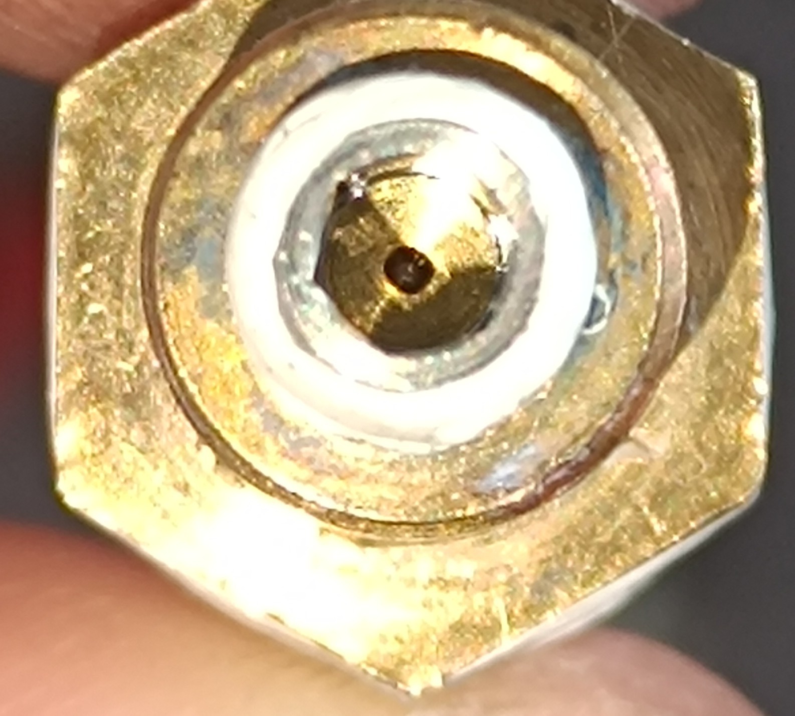
For that, I sanded down the pins on two SMA PCB connectors and soldered them together. Then, I soldered a wire to a nut that was part of another SMA connector. After that, I screwed the two soldered-together SMA connectors into a 1/4-inch plastic fitting and screwed the nut onto the SMA connector's thread, which I secured with a screw locking ring. Finally, I pushed the plastic insulation of the SMA connector out with a screwdriver so that it could be used as a conductive tube and connected a silicone tube to its end.
Sensor built from SMA Connector
To shield it from noise, I soldered a wire to a 1/4 brass fitting which I screwed on the plastic fitting with a washer in between to attach it to the 3D printed part.
I then soldered a shorter SMA connector to the wires to connect it to an SMA cable, which I connected to the amplifier.
Shield for Sensor
While this definitely isn't the best design, it still worked.
Drops hitting the Sensor
To get a reading out of it, it was important to connect the oscilloscope to the power supply's ground.
While in theory the SMA connectors which I soldered onto the AD620 amplifier module should connect the oscilloscope to the ground of the module, in reality that wasn't the case, so I had to connect it separately.
Maybe it had something to do with the bridge between S- and ground on the input side.
Ground Connection on the OscilloscopeWith everything connected, it was possible to see a reading on the oscilloscope when the charged drop hit the sense electrode.
Charged Drops visible on the Oscilloscope
And with that, the first charging test was completed sucessfully.
Conclusion:
- It is possible to charge water drops and read when charged drops hit the sensor.
- Shielding seems to be important to not read noise like the mains frequency or noise from power supplies.
- An amplifier is needed to amplify the small voltage from the drop's charge so that it can be read.
- There is more research needed regarding the ground connection of the amplifiers.
- It would be the best to build a custom amplifier for amplifying the charge to learn more about this topic.
- In the future, a better DIY gutter sensor design is needed.
I think it's useful to do such experiments to verify that something works by yourself instead of only relying on informations you have read online. This way you also get something you can base your next experiments on.
For the last month, I tried out different ways to log and monitor the data that the sensors on the machine collect to get a graphical way to watch the operation of the machine over time.
This way it is possible to verify that everything is working as expected and to find problems that would be otherwise hard to detect.
It's also just nice to see your machine's sensor readings on a dashboard :)
I tried out:
- saving the data on my router's FTP server
- saving the data on Google Sheets
- saving the data on InfluxDB
Finally, I ended up saving the data on a MYSQL database that I set up on a Raspberry Pi, which appeared to me as the most independent/universal solution.
In addition to that I installed Grafana on the Raspberry Pi to get a nice way to display the sensor data.
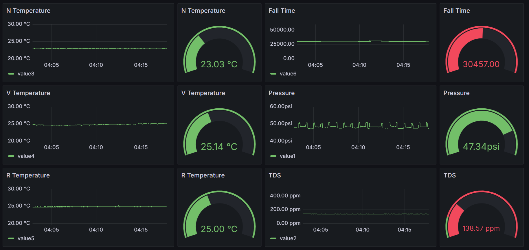
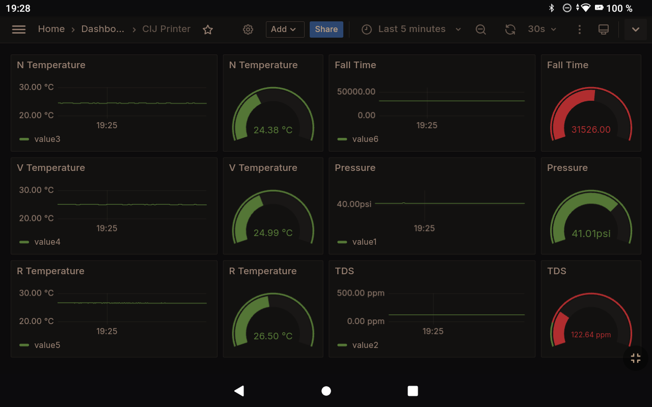
Sensor Reading over 15 Minutes of Operation
In the current picture, all values besides the pressure are as expected, so I still have to find a way to get a stable pressure.
The readings I currently get from the machine are:
- The room temperature
- The nozzle temperature
- The viscosimeter temperature
- The conductivity
- The fall time (the time an 8mm steel ball needs to drop around 100mm in a 10mm PC tube at 25⁰C - equal to the current dynamic viscosity)
- The pressure
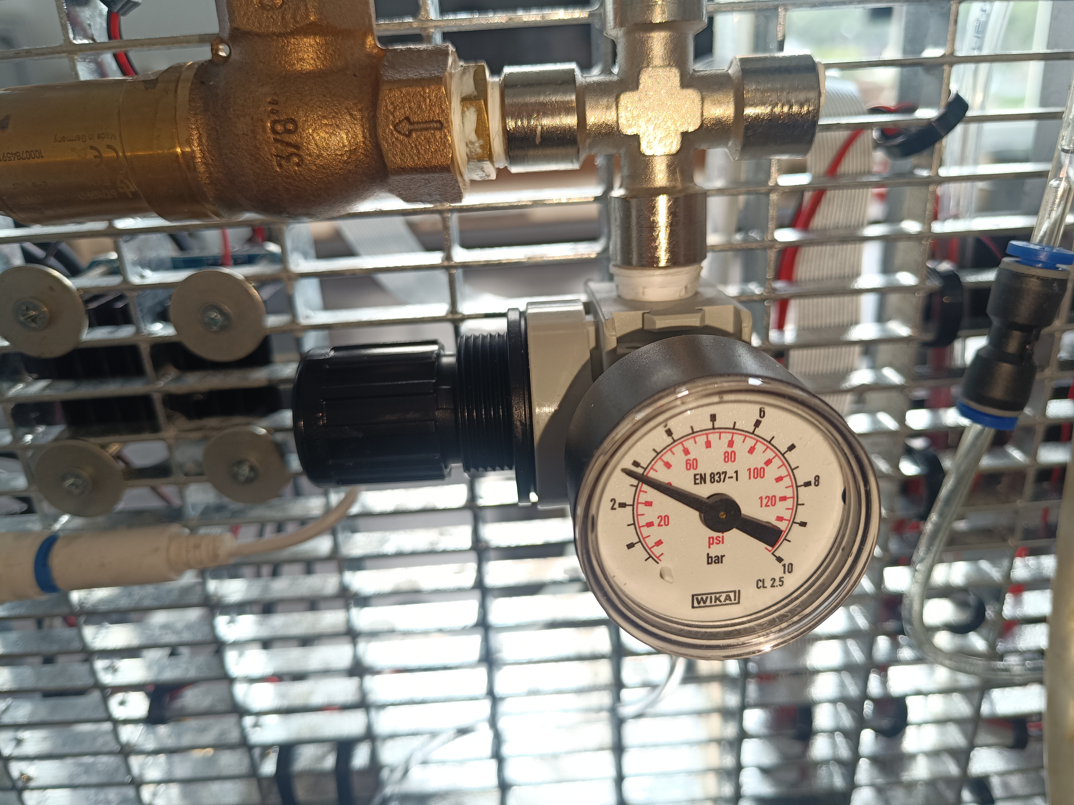
Update:
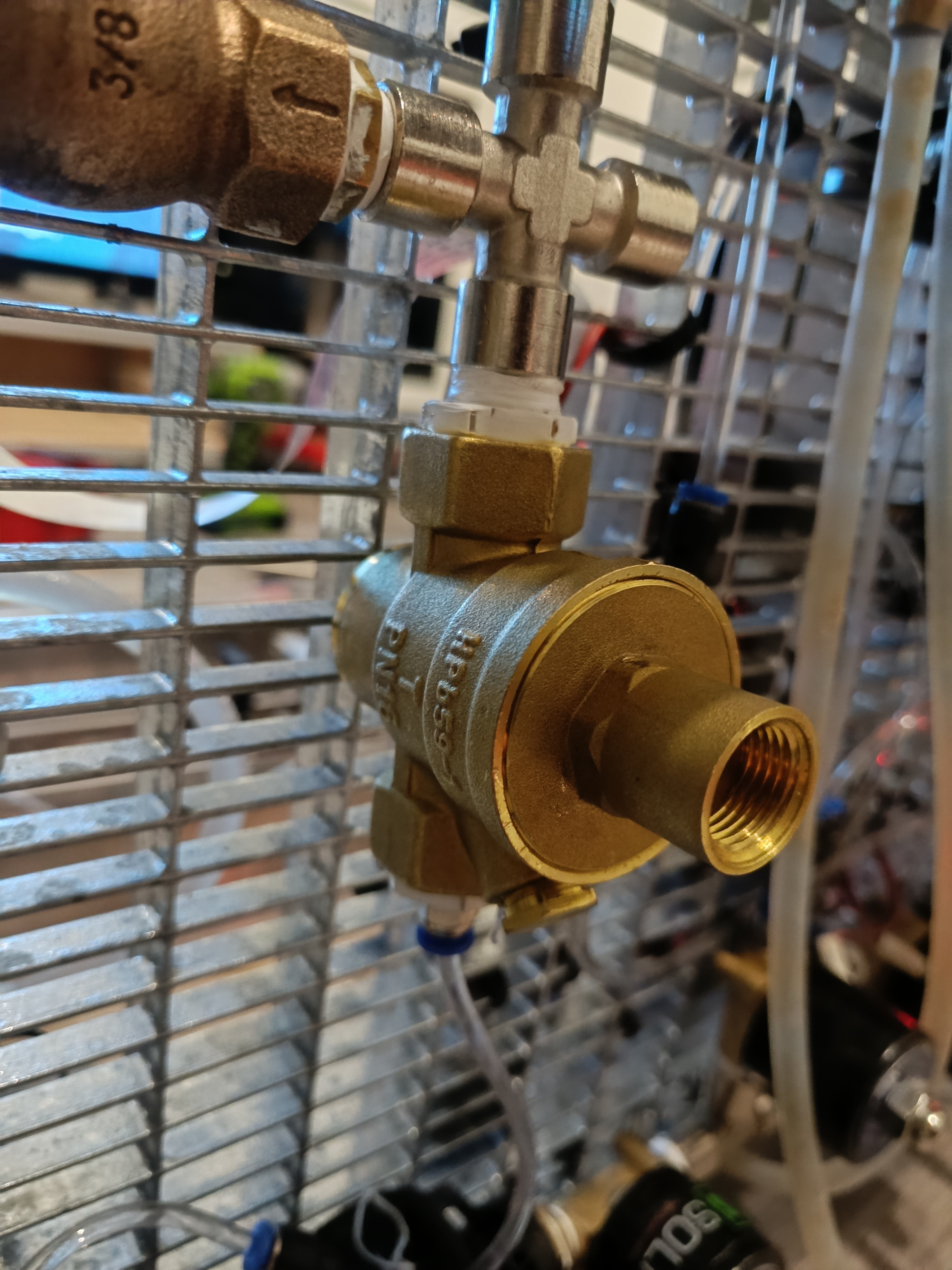
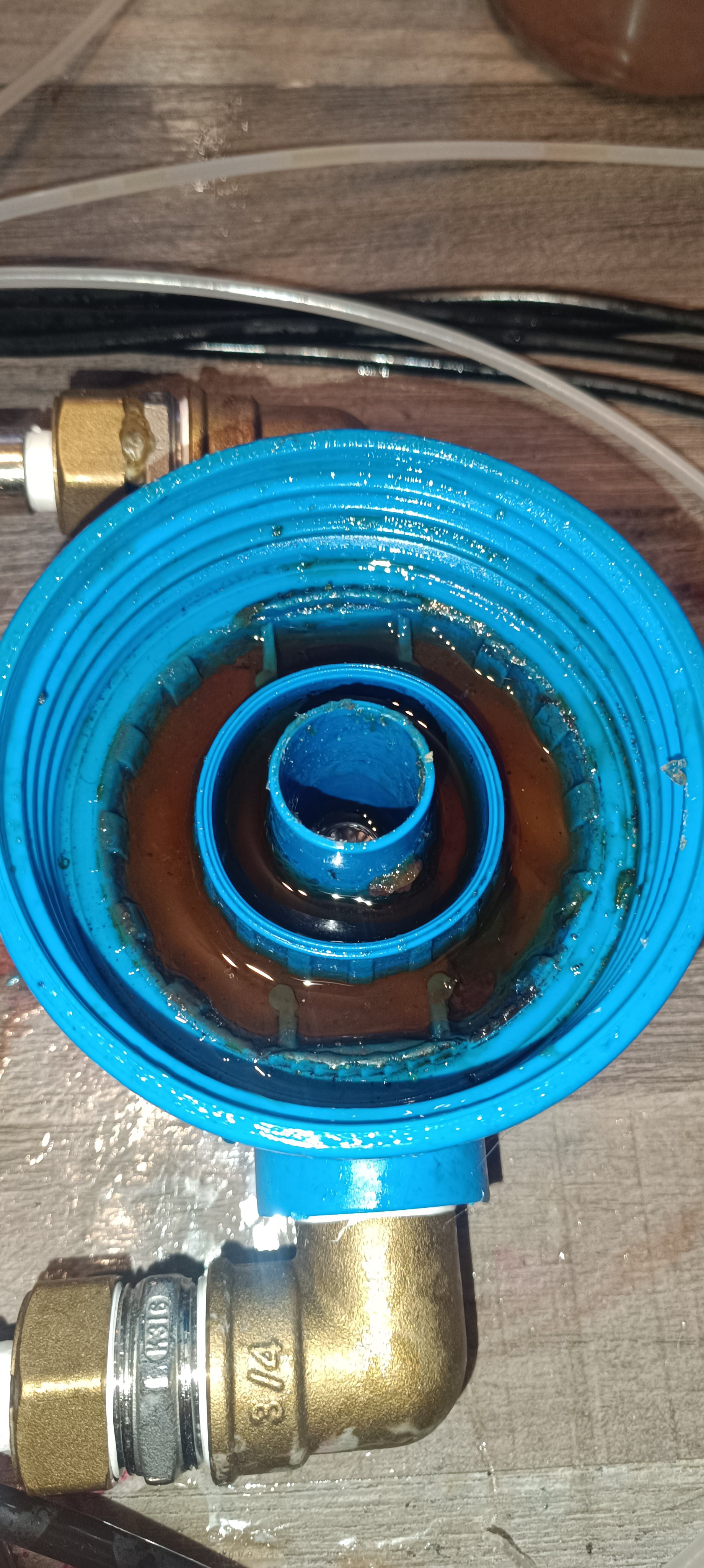
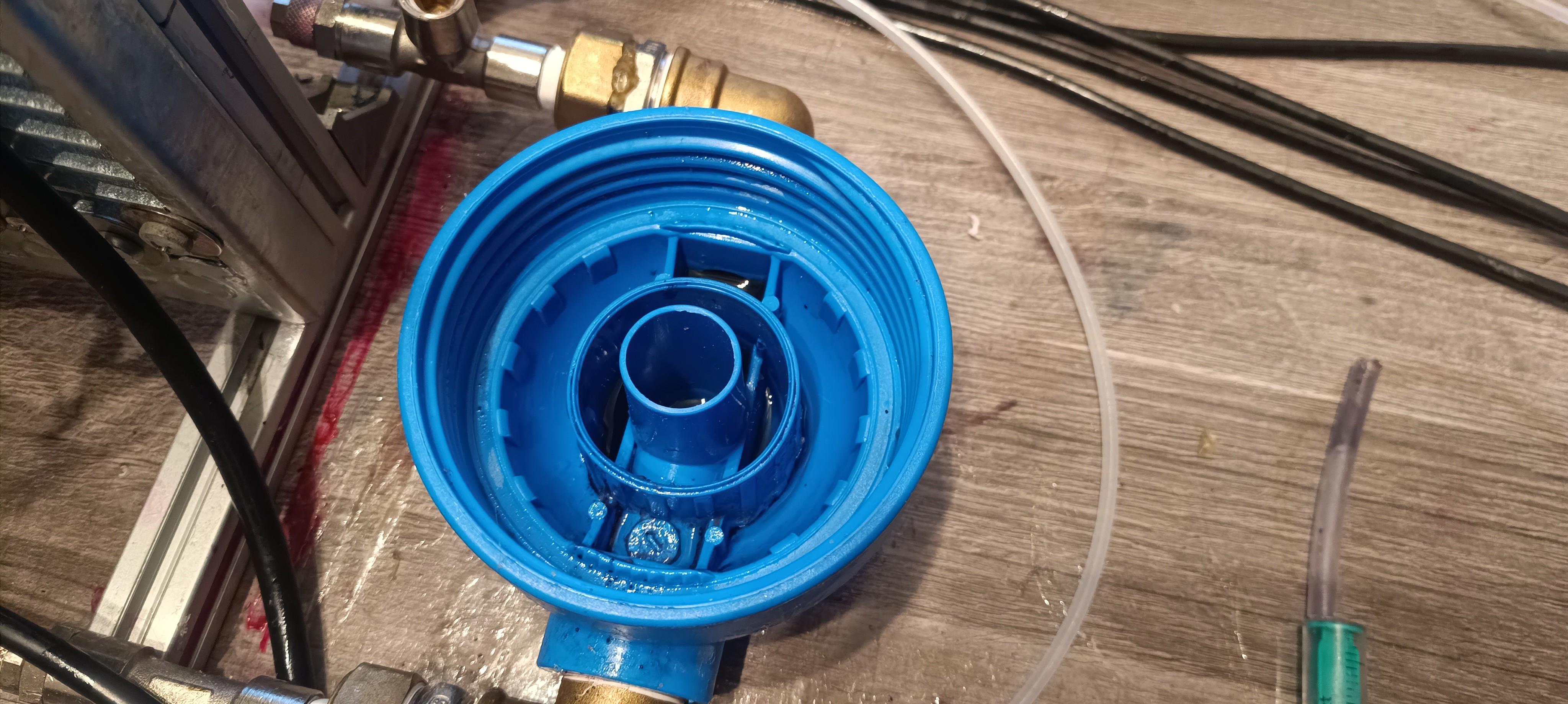
Today, I installed a new pressure regulator which finally outputs a stable pressure.
New Ink Pressure Regulator
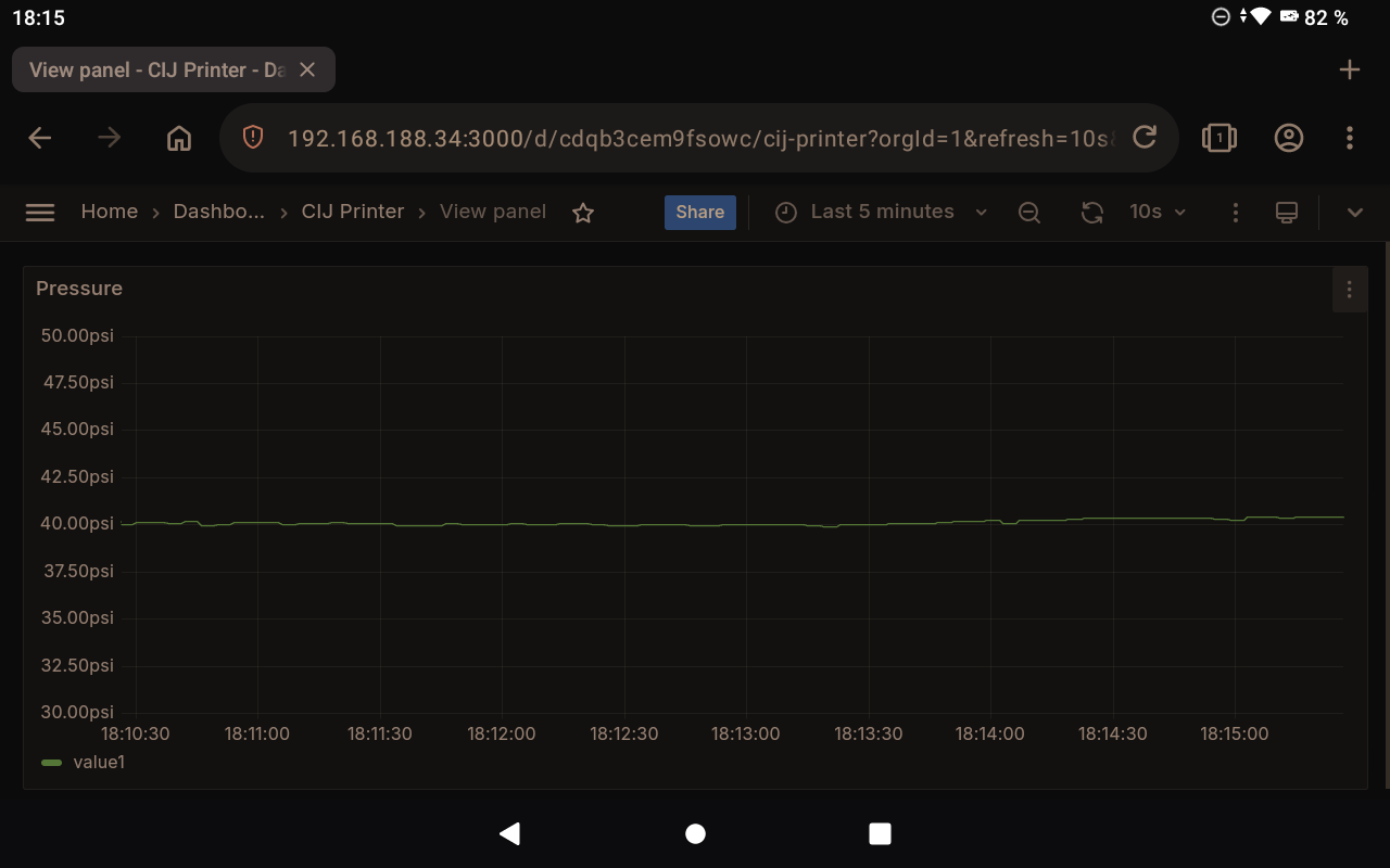
It's also visible in the readings:
Pressure ReadingSensor Dashboard
Now, that all sensor readings are stable the work on the fluid management system is finished until new problems appear and I can finally continue working on the printhead design.
Update:
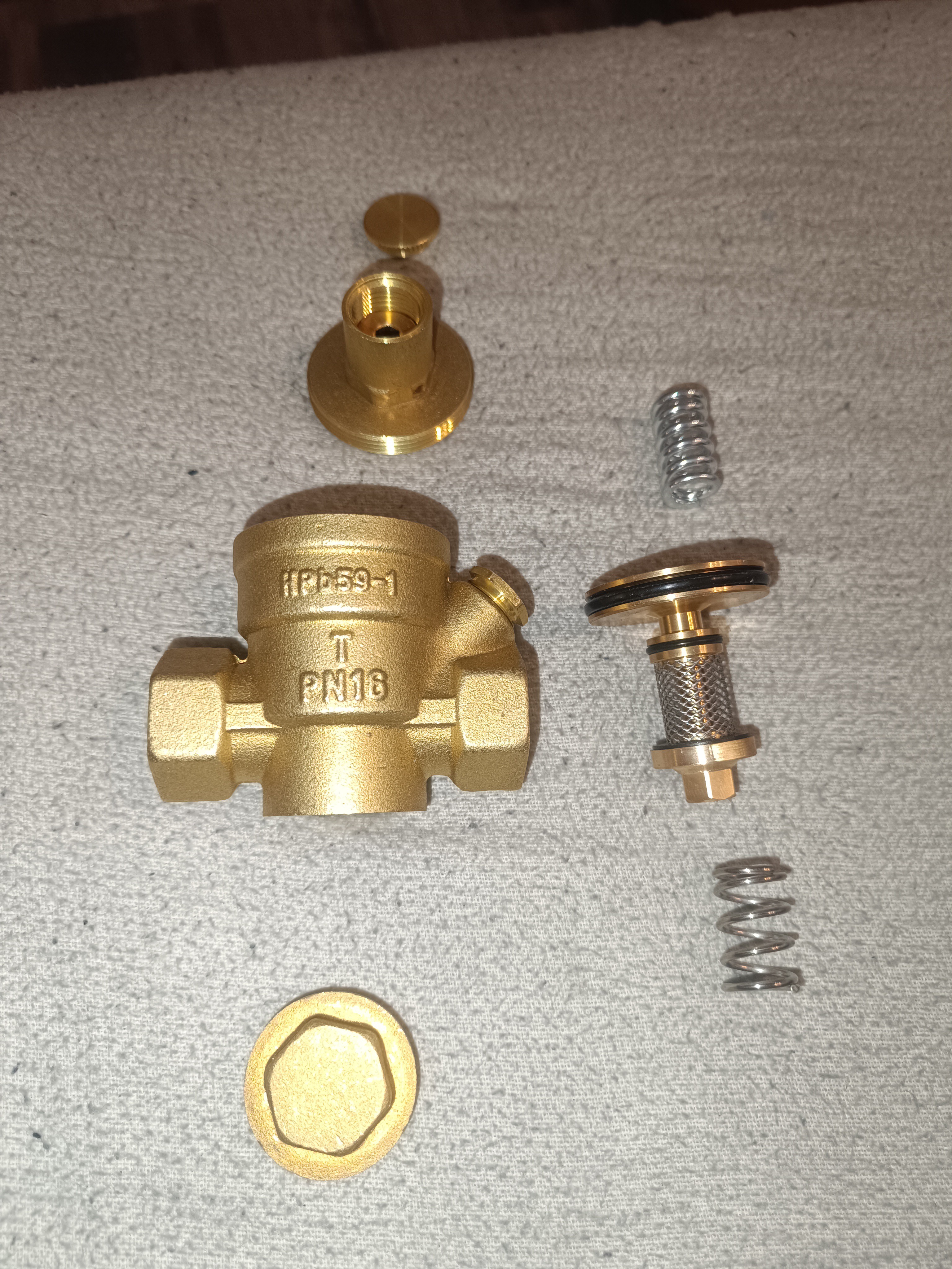
I just found out what caused the pressure regulator to fail:
The pin inside the pressure regulator got stuck, because the used PVB/Ethanol mix is quite sticky. Maybe in the future I can find a pressure regulator with a different design that also works for adhesives or sticky fluids. At least it's no general problem of the system. Until then it's needed to clean and "unstick" the pin of the pressure regulator before running the system.
Another Update:
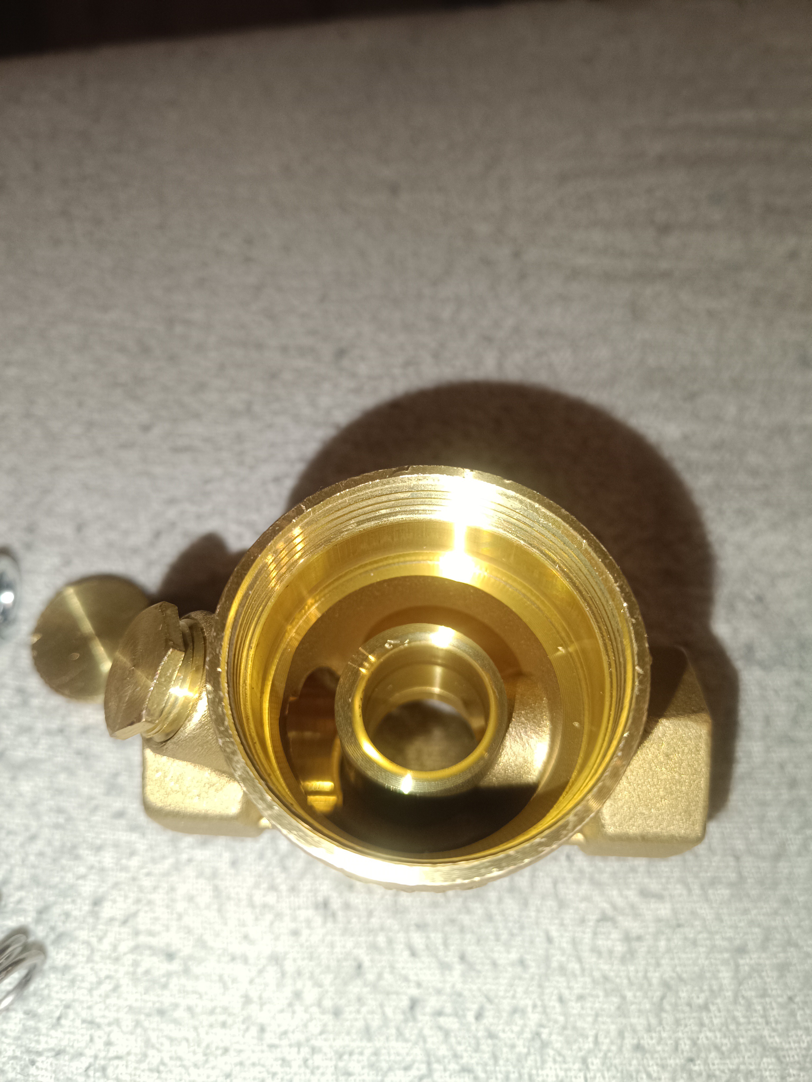
I switched to using another type of pressure regulator which also has a spring at the bottom for closing the seal so that doesn't get stuck open that easily.
Dual Spring Pressure RegulatorView from the InsideParts of the Pressure Regulator
The next thing I want to do is learn more about things like electrostatic induction and conduction and how to measure the charge on droplets.
For this, I'm planning to build a test stand for charging single water drops with variable voltage, detecting when the drops hit a copper mesh, and measuring their charge to learn how to do these things and which factors are important for a successful charge induction and measurement.
When I started working on the new design around Christmas last year the first part I bought was a portafilter coffee machine pump with a high flow and pressure rating.
My initial idea was to use only one single pump for moving all fluid in the system and use a venturi nozzle to generate the needed vacuum for the return line and makeup/solvent loading.
Venturi Valve and Pressure Pump
While it worked well with water and pure ethanol, more and more problems arose as the viscosity increased.
With the high-viscosity ethanol + PVB mixture that I want to use for printing, the venturi valve injected a lot of small bubbles at a high rate into the mixture creating a layer of foam on top of it which kept on rising until the ink tank started foaming over. At the same time, the small bubbles got sucked into the pump causing it to run unstable which would damage the pump over time while creating a loud unhealthy sounding noise.
Foam on the Ink
Over the last weeks, I tried a few things to reduce the foaming problem, but nothing of it could solve it completely...
Small Bubbles mixed with Ink
Another problem with this design was that while the venturi nozzle could still generate a high-flow suction when powered by a high-viscosity fluid, the vacuum level got reduced so much that it could no longer draw in the fluid through the return line...
While this wasn't already bad enough the pump also generated a lot of heat which makes it hard to keep the temperature inside the system constant...
With these problems and the fact that these kinds of pumps are pretty noisy and also quite expensive when bought new, it was time to start working on a better and cheaper solution.
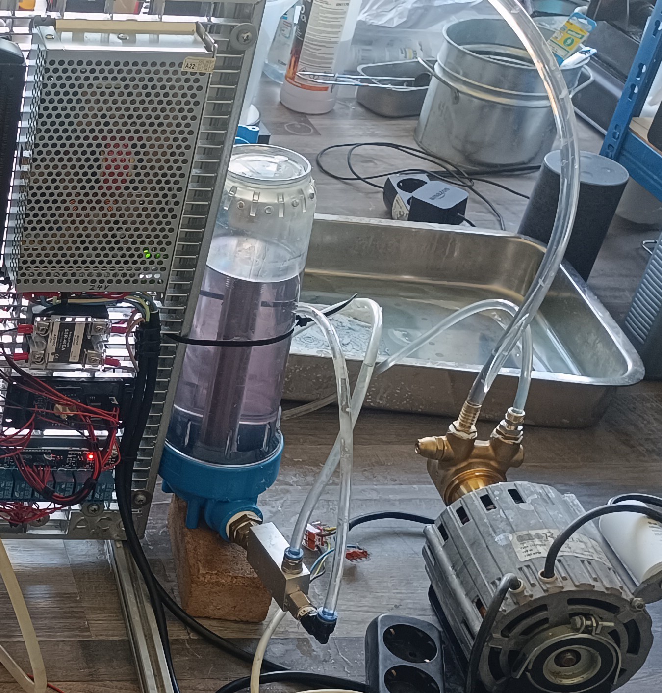
Brushless DC Pump for Ink Circulation
A few weeks ago I already added two small 24V brushless pumps to the printer for ink circulation inside the viscosimeter and for water cooling.
While thinking about the changes needed for replacing the large pump I realized that the viscosimeter circulation pump can also be used for circulating all the ink inside the printer and not only the ink inside the viscosimeter. Because of that I could remove the valves needed for the "viscosimeter sample refresh" function and just keep the pump circulating the ink all the time.
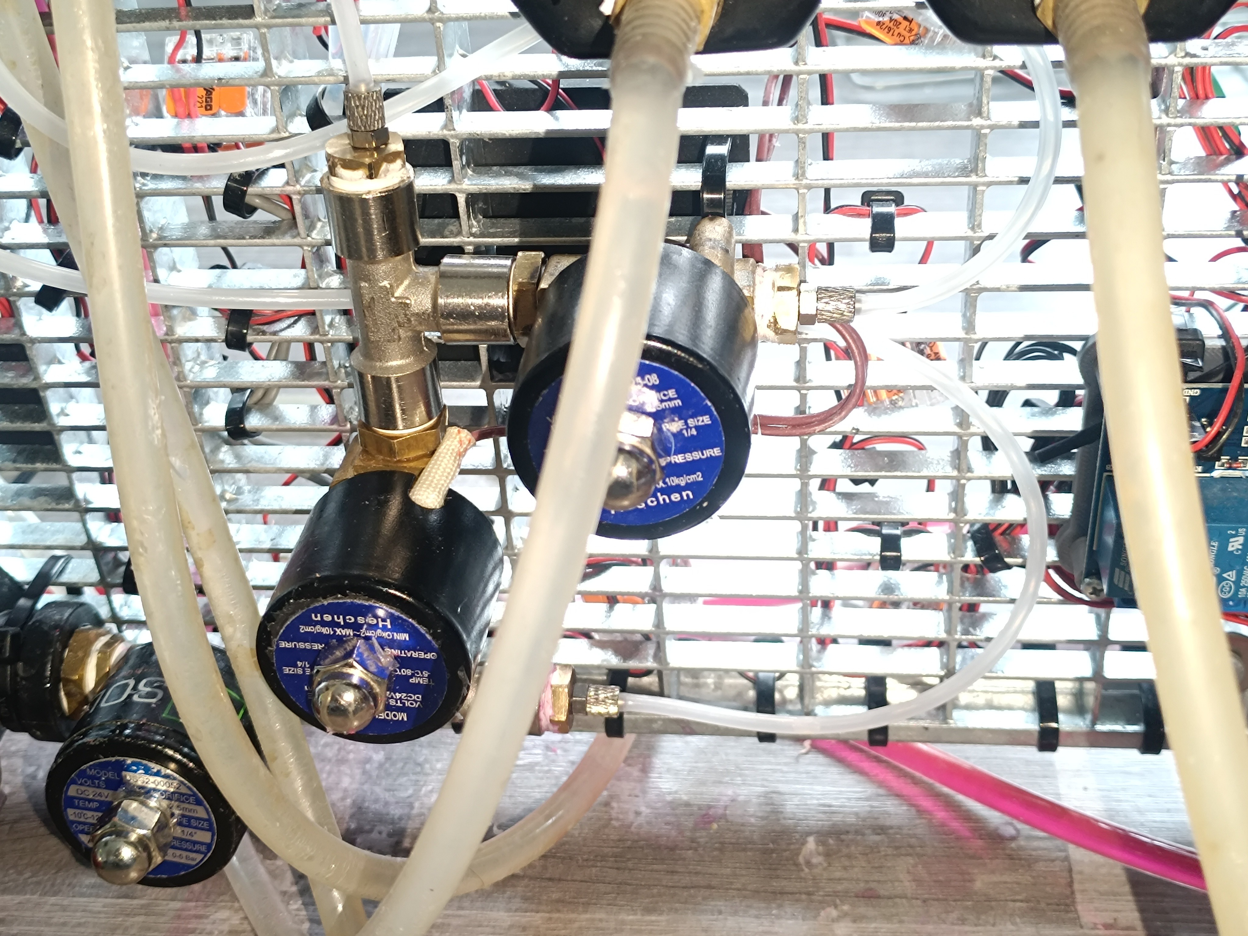
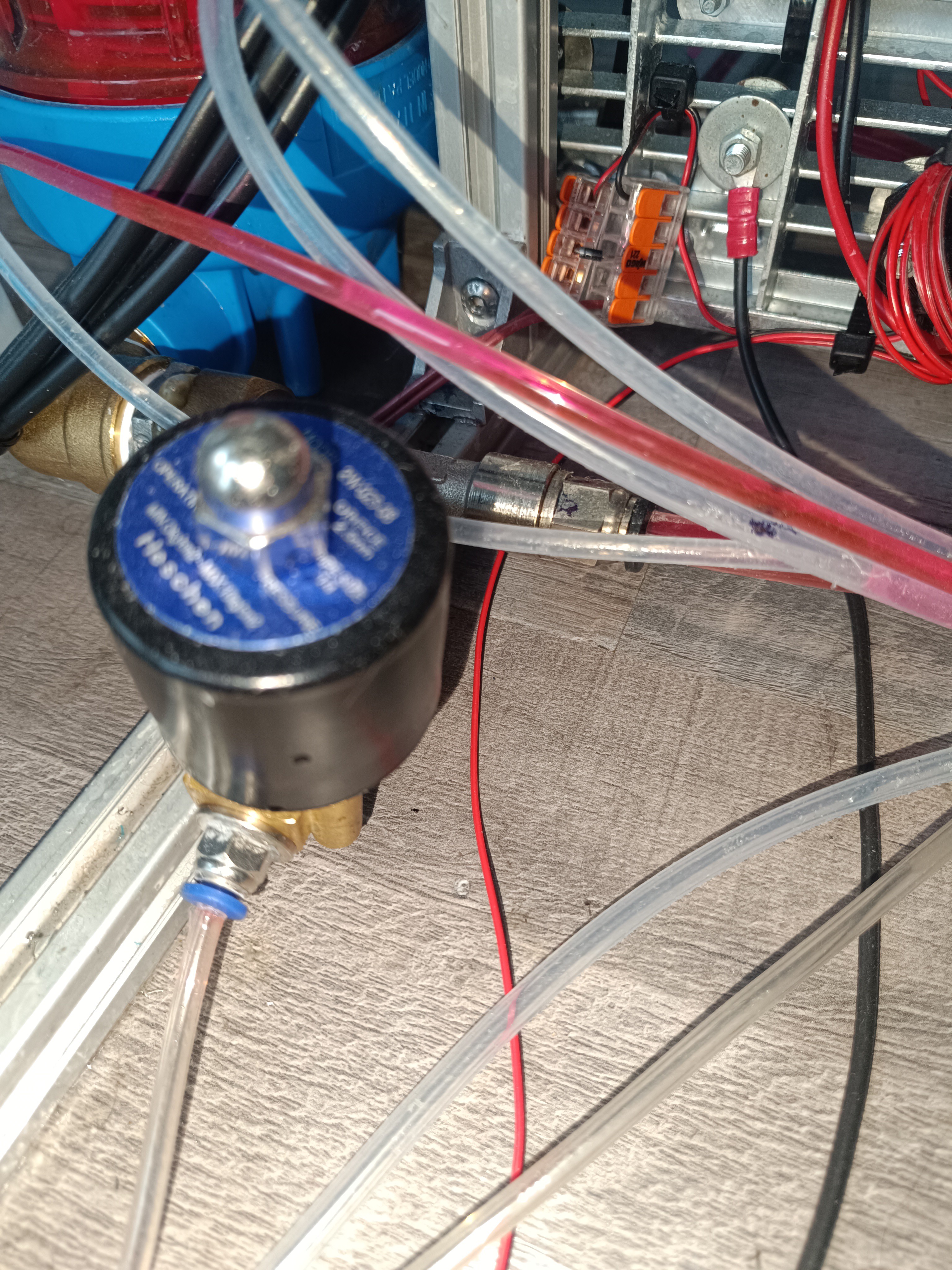
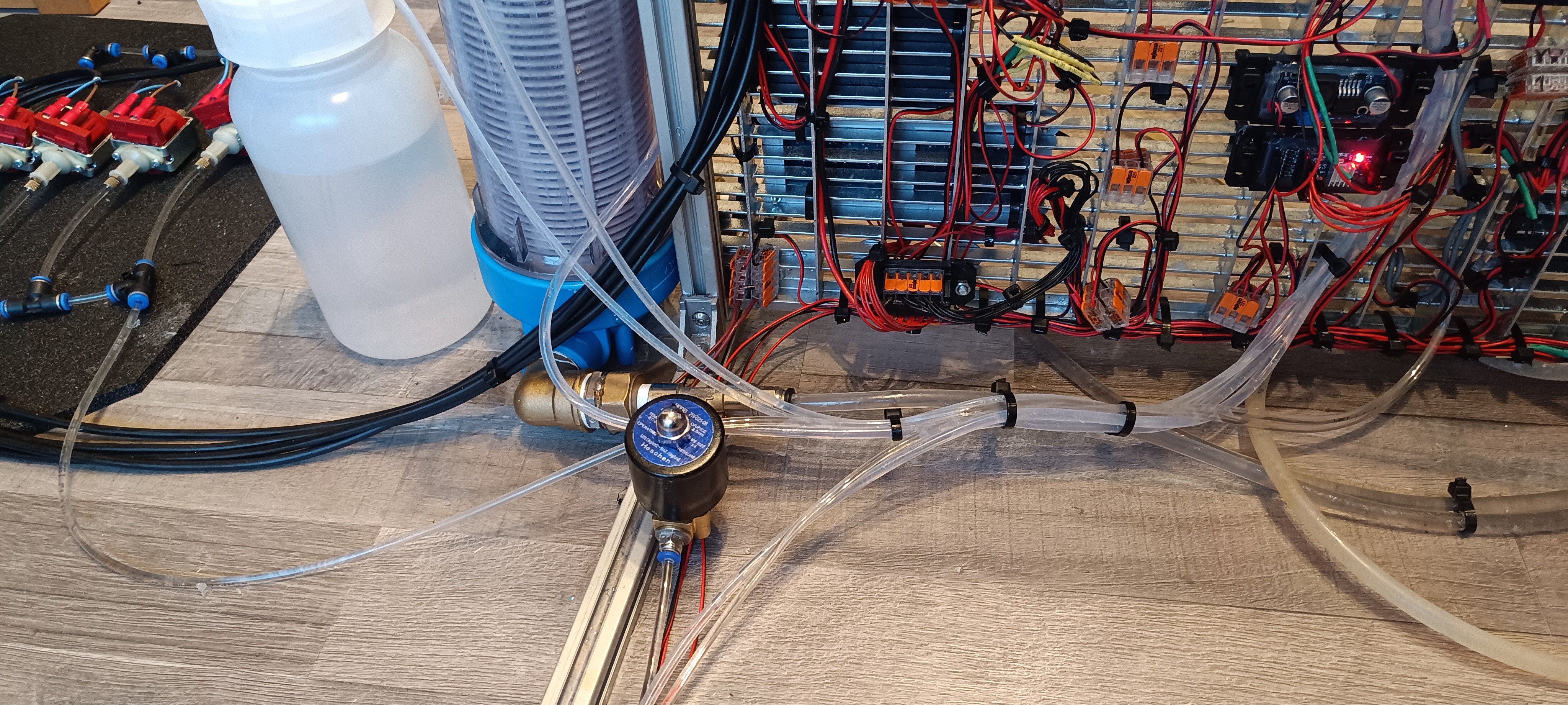
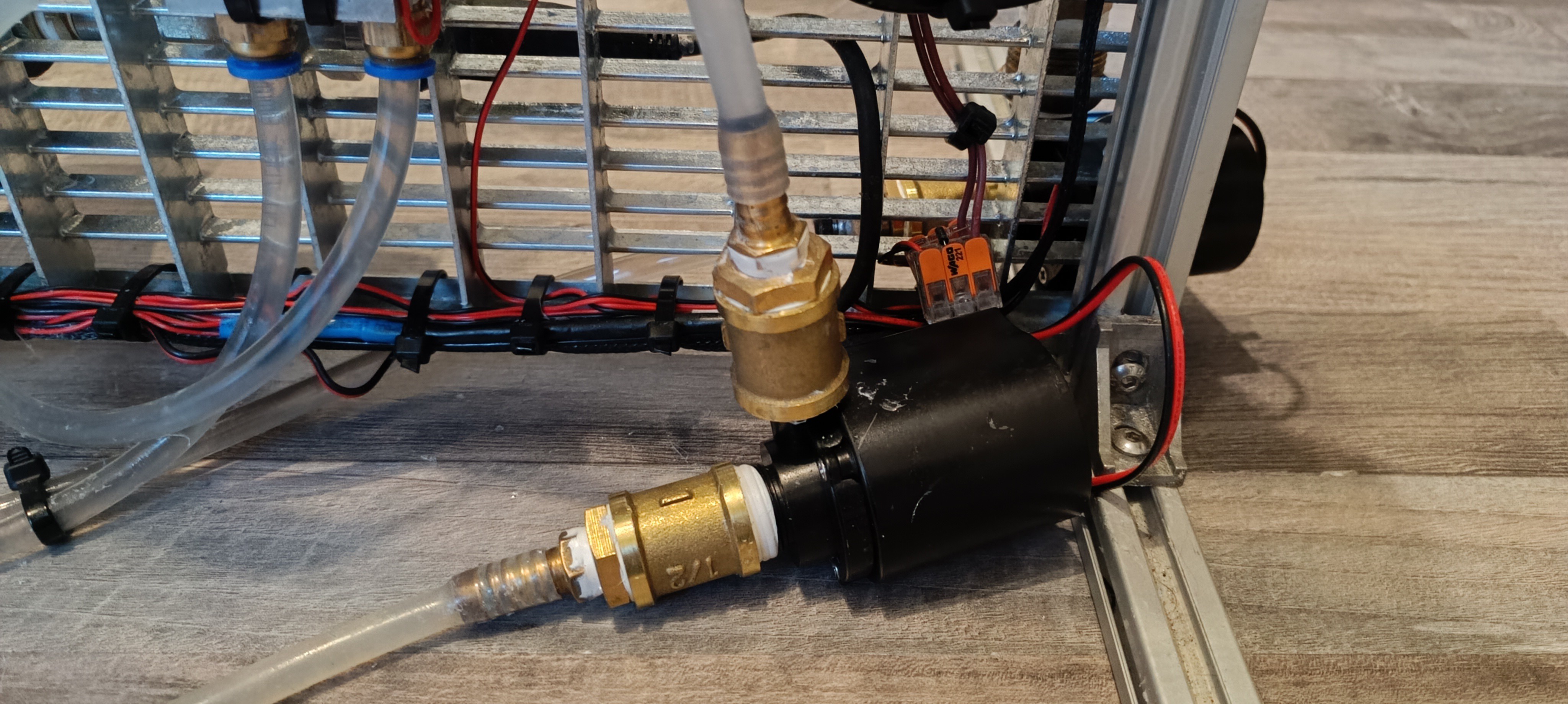
For lifting the steel ball inside the viscosimeter a solenoid valve connected parallel to the pump outlet can be opened from time to time.
The ink flows from the ink tank to the circulation pump and gets pumped to the viscosimeter.
Outlet of the Ink Tank
Ink Circulation Pump
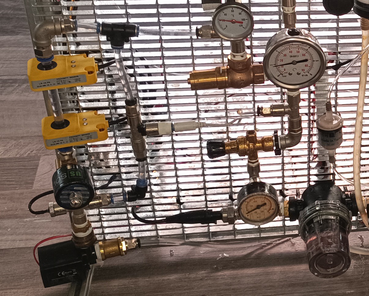
From there it flows into a T fitting which is connected to the outlet of the relief valve that regulates the pressure of the pressurized part of the system.
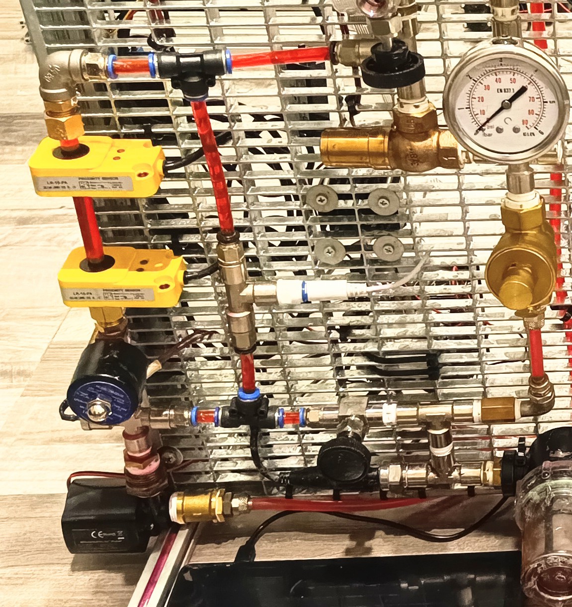
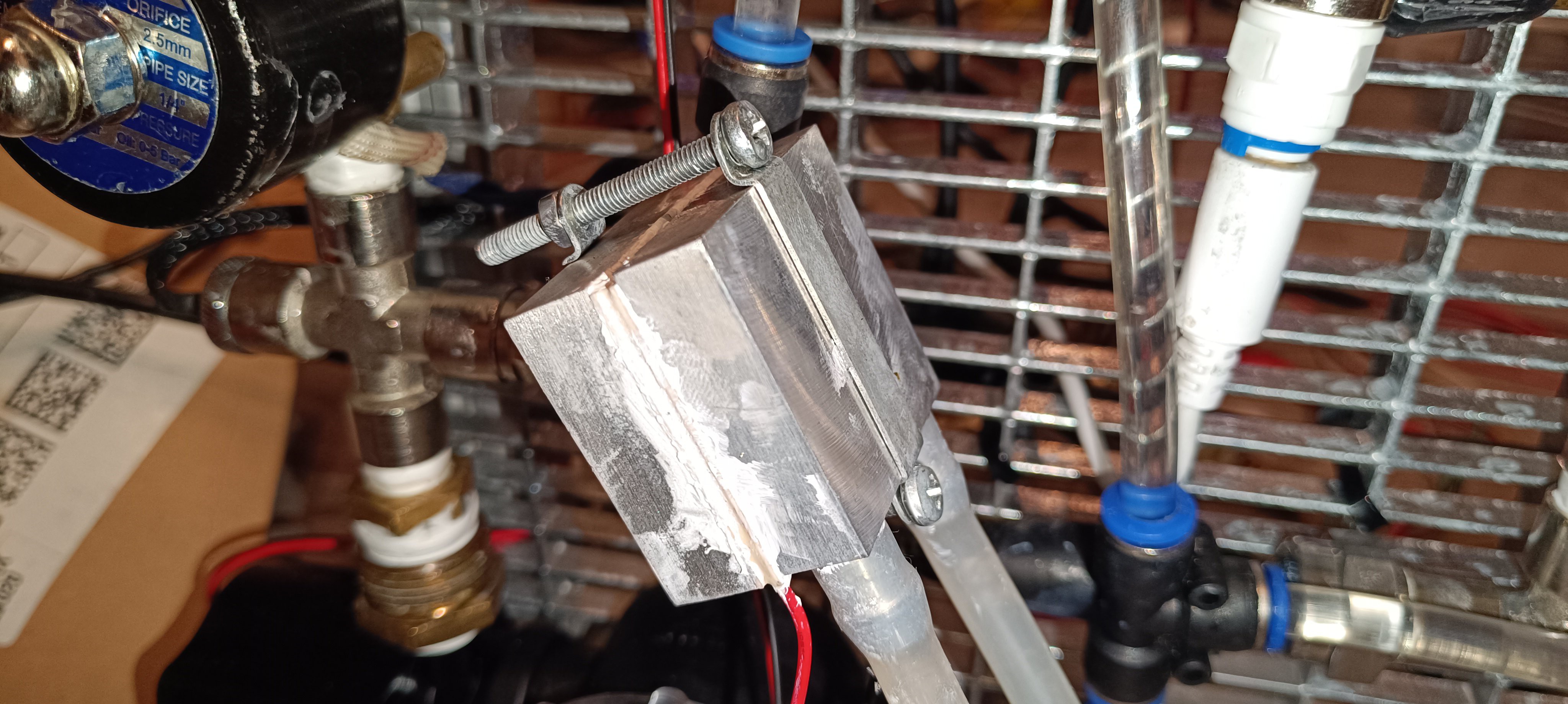
Viscosimeter
From there the ink flows into the heat exchanger that keeps the ink at 25⁰C by heating and cooling it.
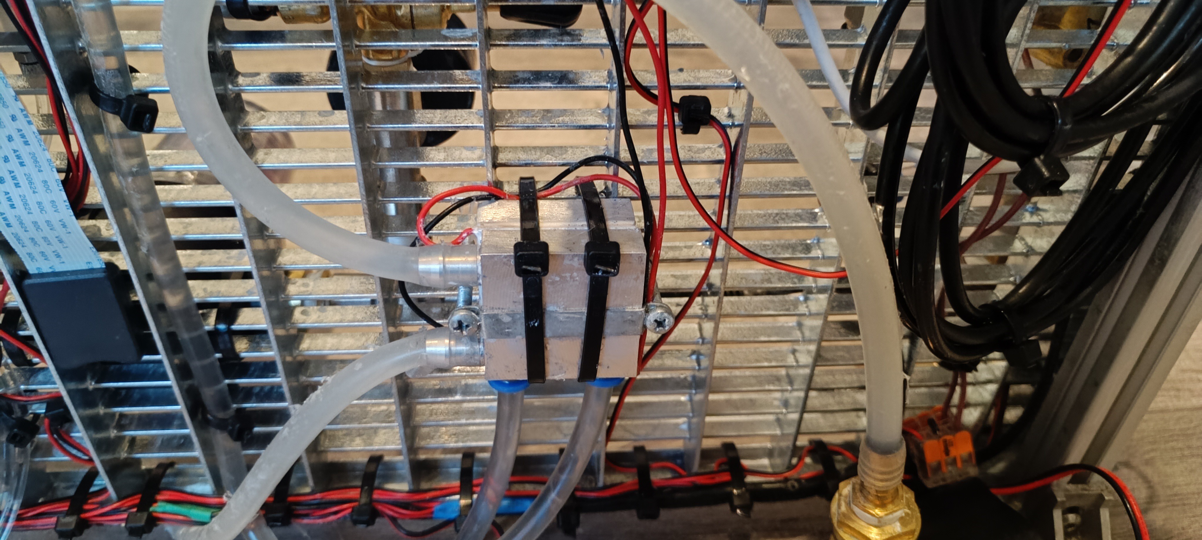
Heat Exchanger
Finally, the ink enters the ink tank again to complete the cycle that keeps the ink well-mixed and at a steady temperature.
Inlet of the Ink Tank
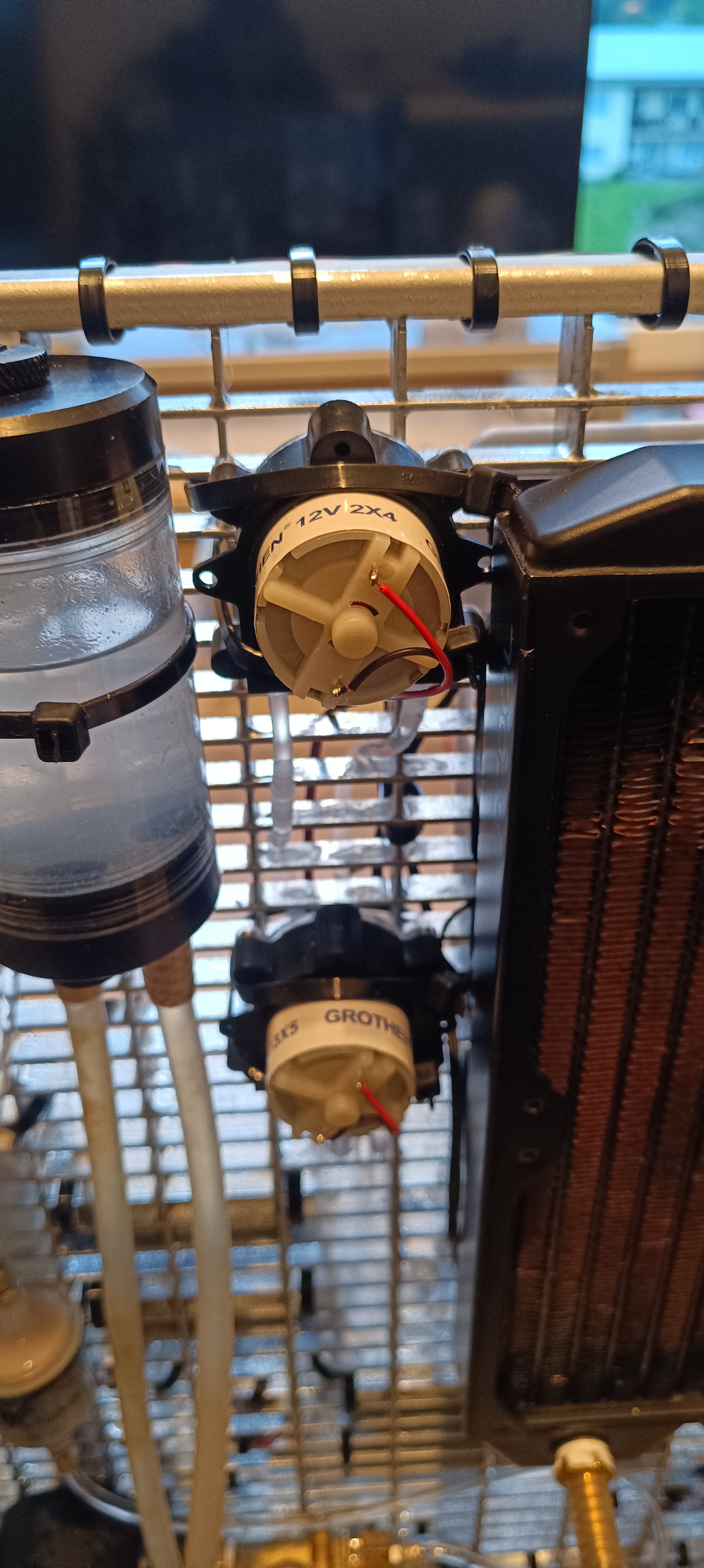
Brushless DC Pump for Water Cooling
The water cooling system is used for cooling a TEC 12706 Peltier module for heating up or cooling down the ink so that it can be kept always at 25⁰C independent from the room temperature.
The water flows from the water reservoir tank to the circulation pump and gets pumped into the heat exchanger.
Water Cooling Pump
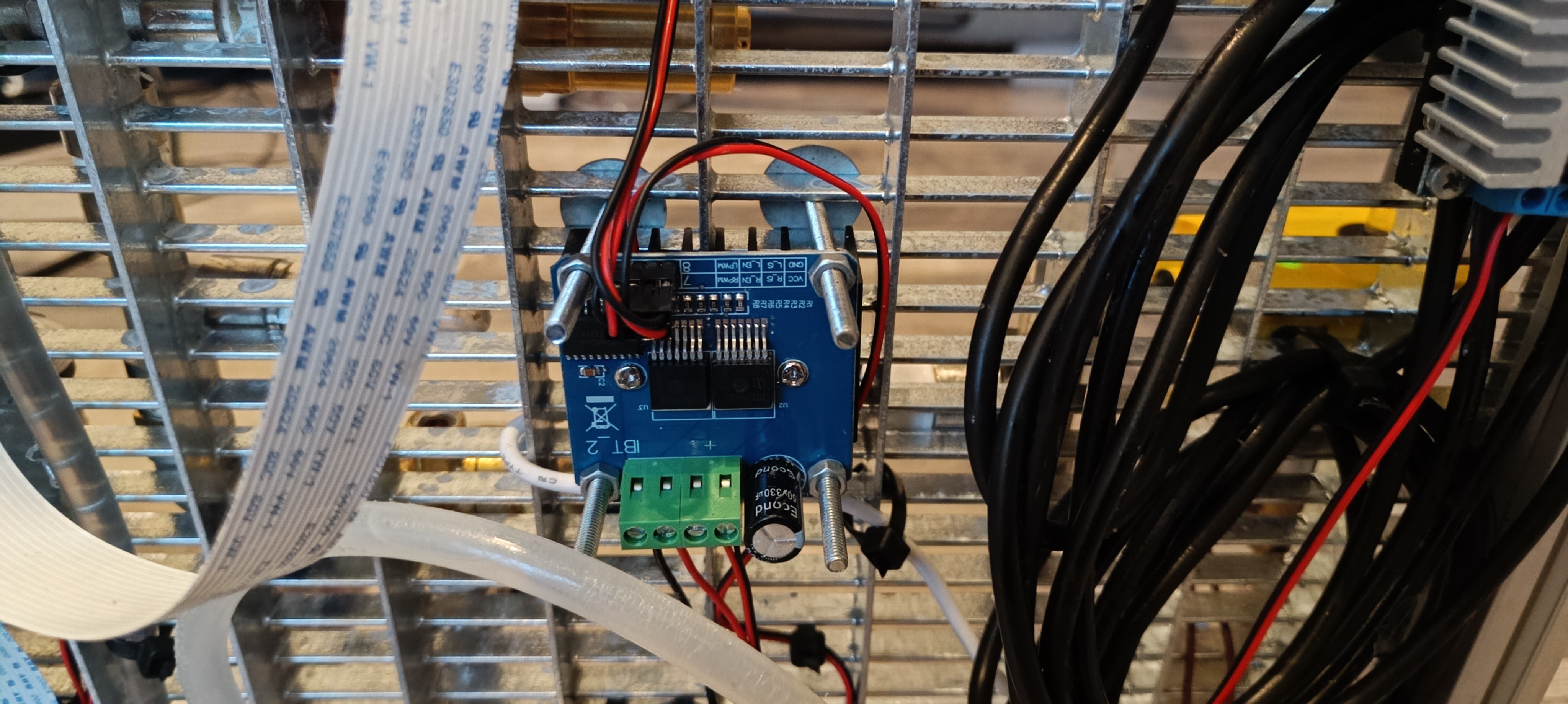
Heat ExchangerThe Peltier module is driven by a BTS7960 H-Bridge module so that it can be used for cooling and heating as well.
BTS7960 H-BridgeThe H-Bridge is powered by an XL4016 step-down converter module which outputs 12V.
XL4016 Step Down ConverterFrom the heat exchanger, the water flows into the radiator and from there it flows into the water reservoir tank to complete the water cooling cycle.
Radiator and Water Reservoir Tank
Peristaltic Pump for Solvent/MakeUp
For adding solvent/makeup (ethanol) to the mix I switched to using a peristaltic pump instead of the vacuum line. This pump should be able to add always the same amount of ethanol to the mix when running at the same speed for the same amount of time.
Peristaltic Pumps
The ethanol is drawn from the bottle next to the tank and flows from the pump into the cross-fitting at the top of the tank.
The side connections of the cross-fitting are for makeup and return line and the top connection is for adding pre-mixed Ethanol/PVB ink and venting the air from the return line out.
A quick note here:
While writing this project log I just had the idea to relocate the two valves on the printhead over to the machine frame.
These valves are used for applying the vacuum either to the nozzle or to the gutter.
Two Valves on the Printhead
At the moment the printhead is mostly disassembled and only used for testing the fluid lines.
When everything related to fluid management is working nicely and reliably, I will build a separate prototype only for the printing electronics to ultimately merge both parts into another revision of the project.
Since this is the most complicated project I ever worked on, it will still take a long time until it can be used for anything useful.
Printhead without ValvesNew Location of the Valves
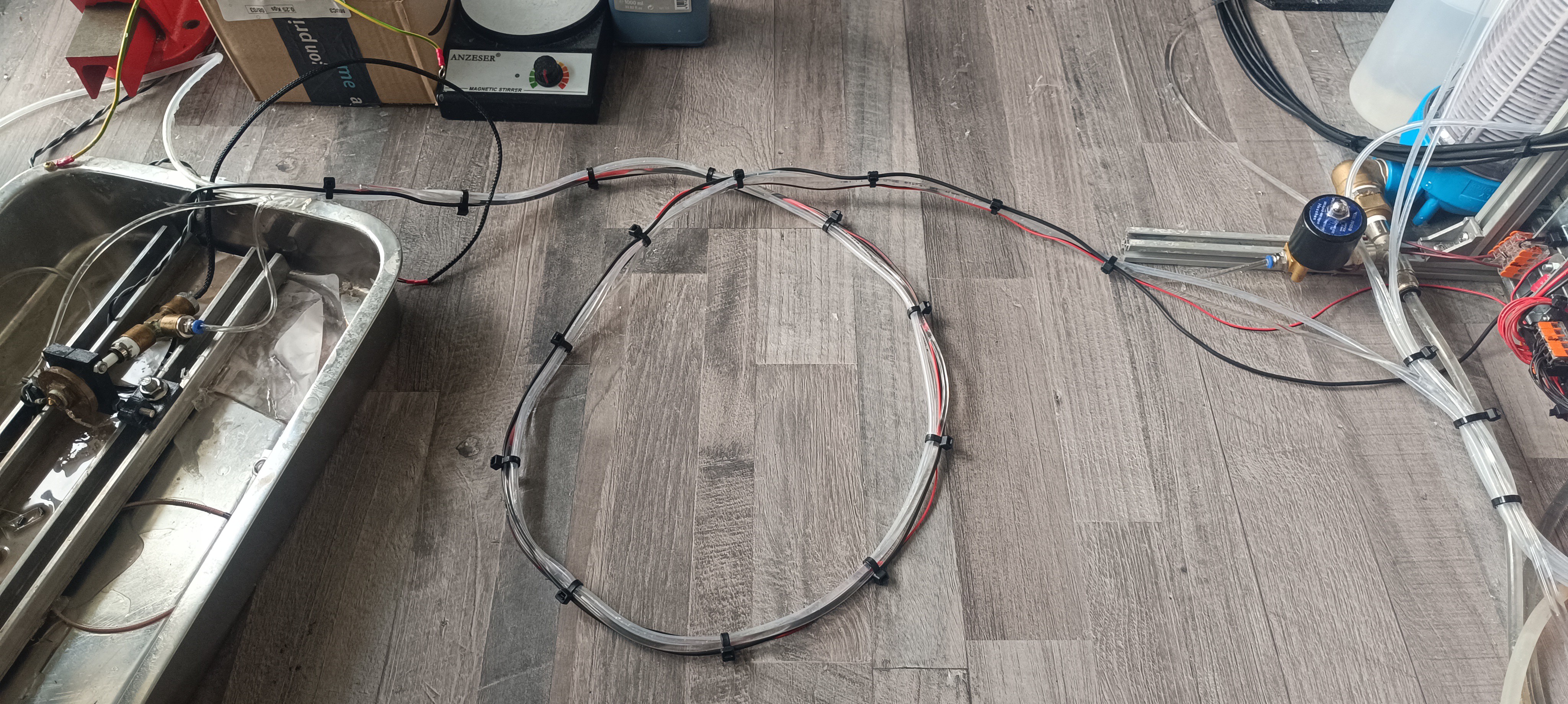
Currently, the printhead is connected to the printer via a 3m long connection line consisting of a ground wire for ESD protection, a cable connection to the nozzle thermistor that checks the ink temperature at the nozzle, the ink line which supplies pressurized ink or vacuum for cleaning to the nozzle, the return line which draws the ink back to the printer and a flush line which is connected to the ink tank that can be used for flushing the nozzle line and return line by applying vacuum to the line that needs to be flushed and connecting the flush line to this line. The vacuum draws the ink from the tank through the line that should be flushed to the peristaltic pump and from the pump back into the ink tank which has a mesh filter inside for separating any dirt that may get flushed out of the line.
3m long Connection Line to the Printhead
Peristaltic Pump for the Return Line
When I tested out the first peristaltic pump for adding makeup, I was surprised at how well these pumps can generate suction.
The generated vacuum level is higher than that of the venturi nozzle when driven with high viscosity fluid and the flow is much lower so that not as much air gets sucked in that could mix with the ink to form bubbles or foam.
Replacing the venturi with a peristaltic pump has not only the advantage that it solves the bubble/foam problem, it also lowers the required high-pressure flow rate, because now, without the venturi nozzle, the only thing on the printer that requires high pressure is the ink stream through the 0.1mm nozzle which only requires a very low flow rate what makes it possible to use other types of pressure pumps for the printer.
The return pump pumps the ink back into the cross-fitting on top of the ink tank which generates a vacuum on the input side of the pump that is used for either returning the ink from the gutter or cleaning the nozzle.
For returning the ink from the gutter, the gutter valve is opened so that the ink from the ink stream hitting the gutter block/pipe can be drawn back into the printer. This is normally done as long as the printer is active and the ink stream is present.
For returning the ink from the nozzle, the gutter valve is closed and the nozzle vacuum valve is opened, so that the ink can flow backward through the ink line via the return line back into the tank. This is normally done to clean the nozzle with either pure ethanol or ink from the flush tube.
While only a small amount of pure ethanol should enter the system to not dilute the ink too much, the flush tube can be used as long as needed for flushing particles out of the nozzle/ink line that may block the nozzle again if they don't get completely flushed out of the ink line.
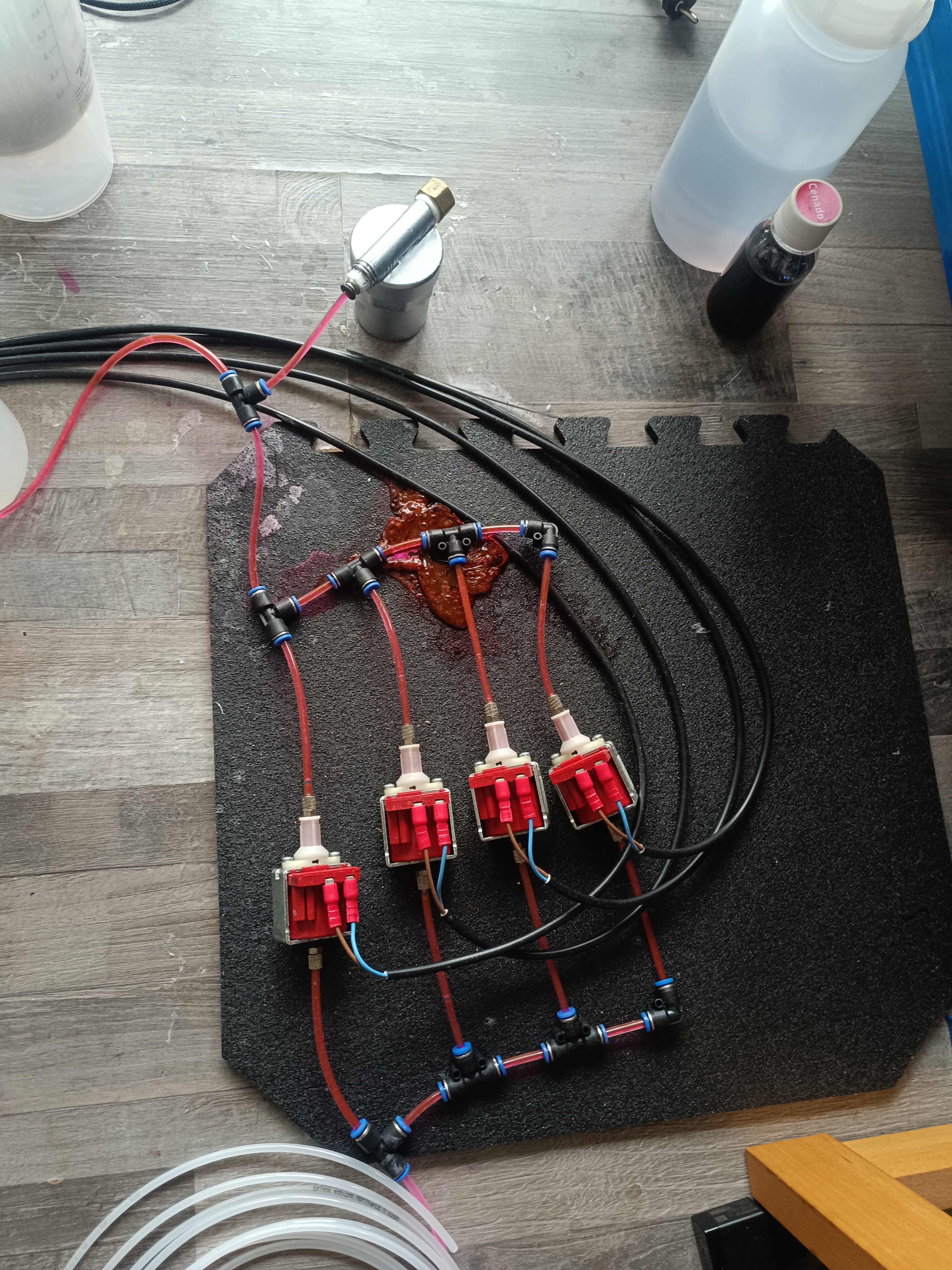
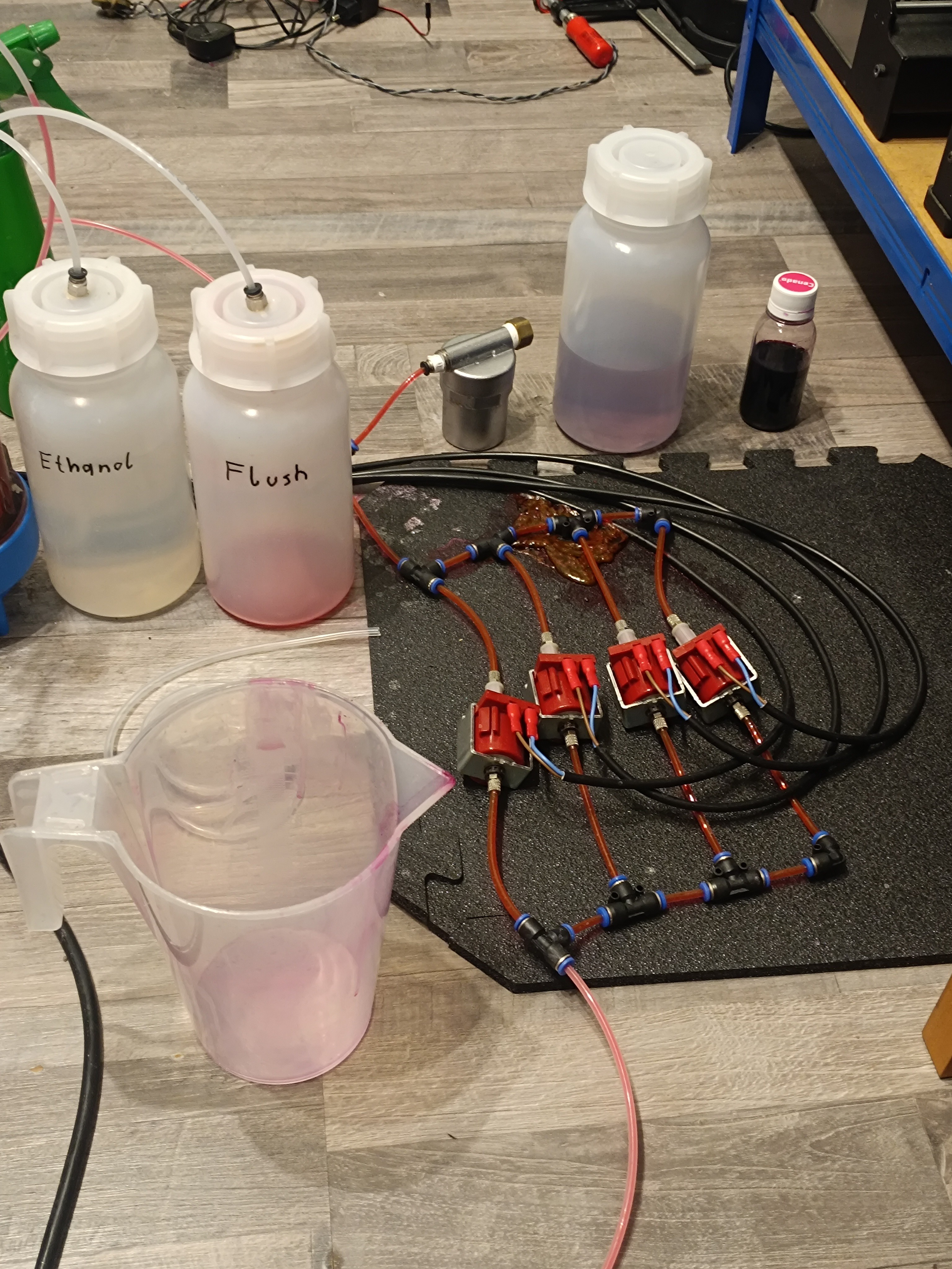
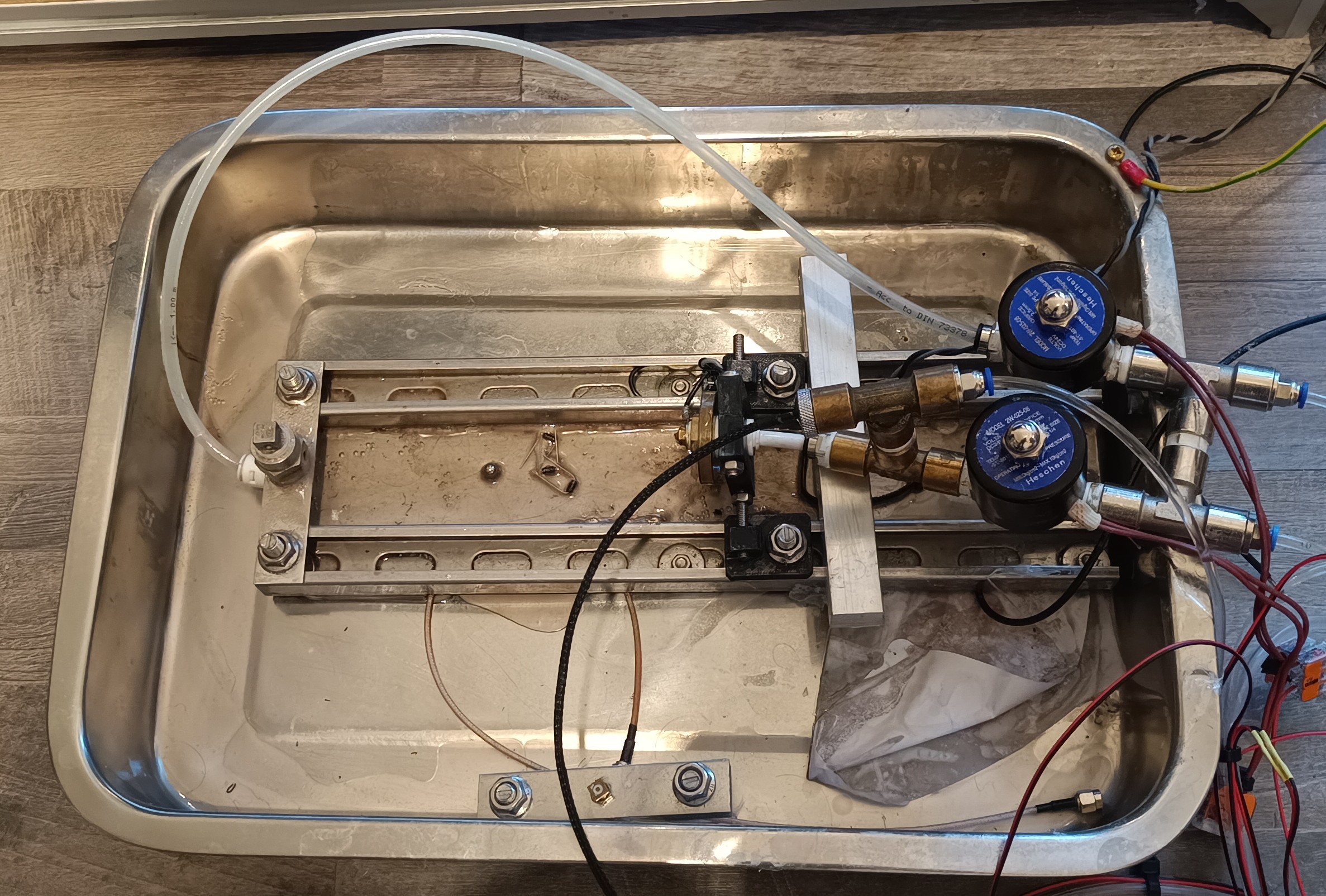
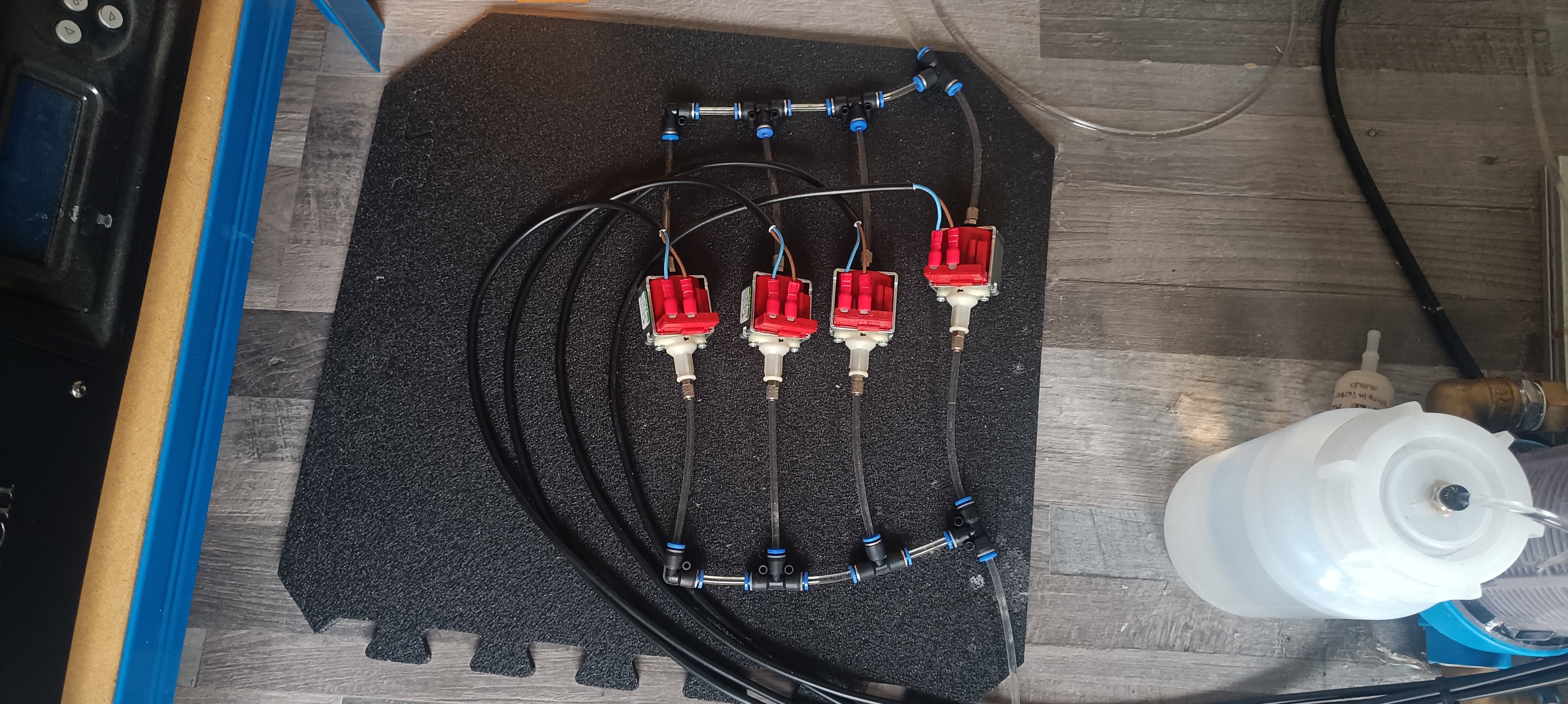
New Pressure Pumps: 4 Solenoid Pumps
Since the high-pressure flow requirement got much lower with the new design, it is now possible to use other pressure pump types for generating the needed pressure and because small solenoid pumps like the ones used in cheap coffee and fog machines don't make a lot of noise, I decided to use them for generating the needed pressure.
These pumps are available in many different sizes with different flow, pressure, and power ratings. While the smaller ones are very quiet, the larger ones make a louder humming noise.
While some models can run at 100% duty cycle, most of them are only rated for running in 1 min on / 1 min off cycles to prevent them from overheating. This is the major drawback of this kind of pump.
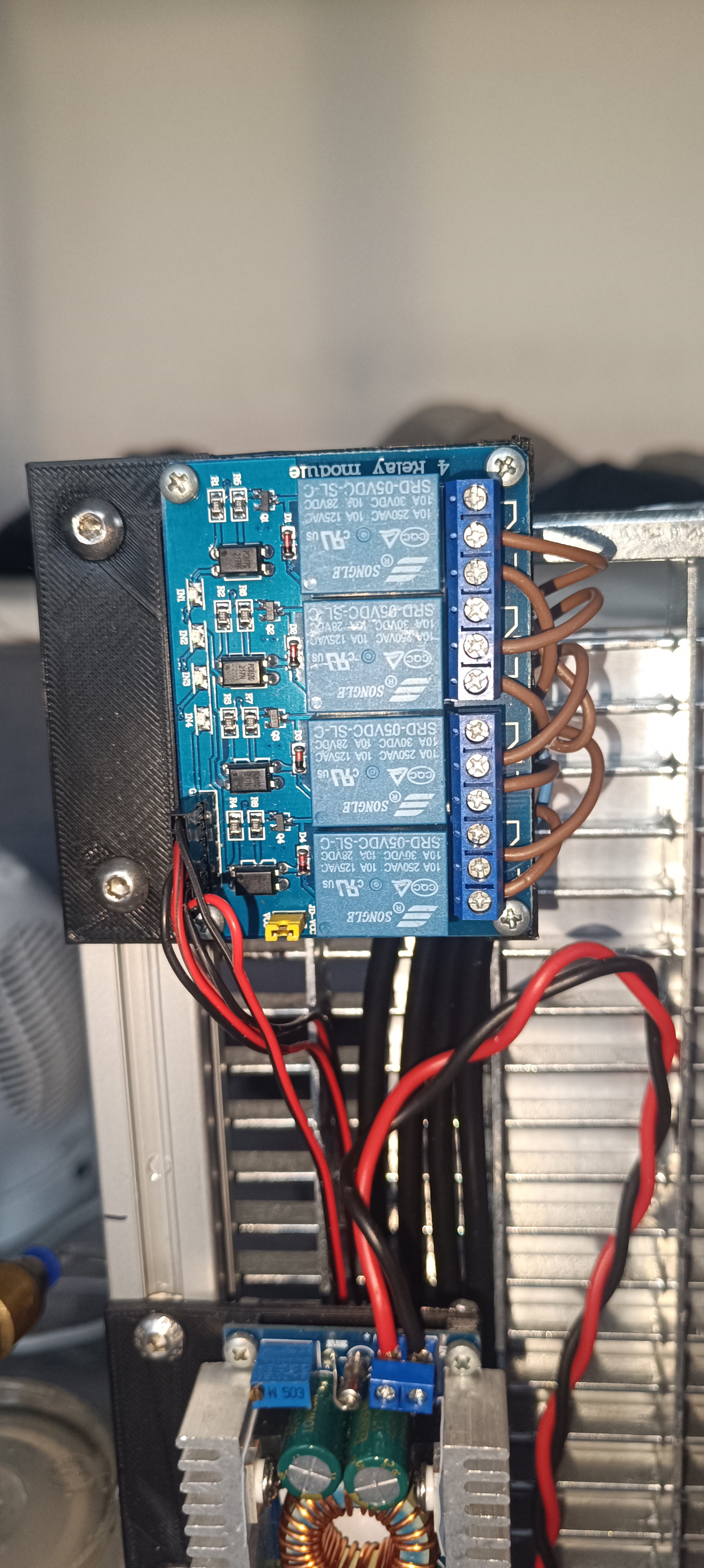
To deal with it, I'm currently using four of them connected in parallel to the ink line wired to a 4-channel relay module to run them one by one with a few seconds of overlapping to prevent the pressure from dropping while switching.
Four Solenoid Pumps connected in parallel4 Channel Relay Module
This way each pump is 1 minute turned on and 3 minutes turned off, which is 3 times the required off time for this model. While testing, they heated up, but not enough to be worried about melting the plastic around the coil.
I'm currently using 4 of the ULKA NMEHP Type 1S models, which are small and silent pumps with a 1 min on / 1 min off rating.
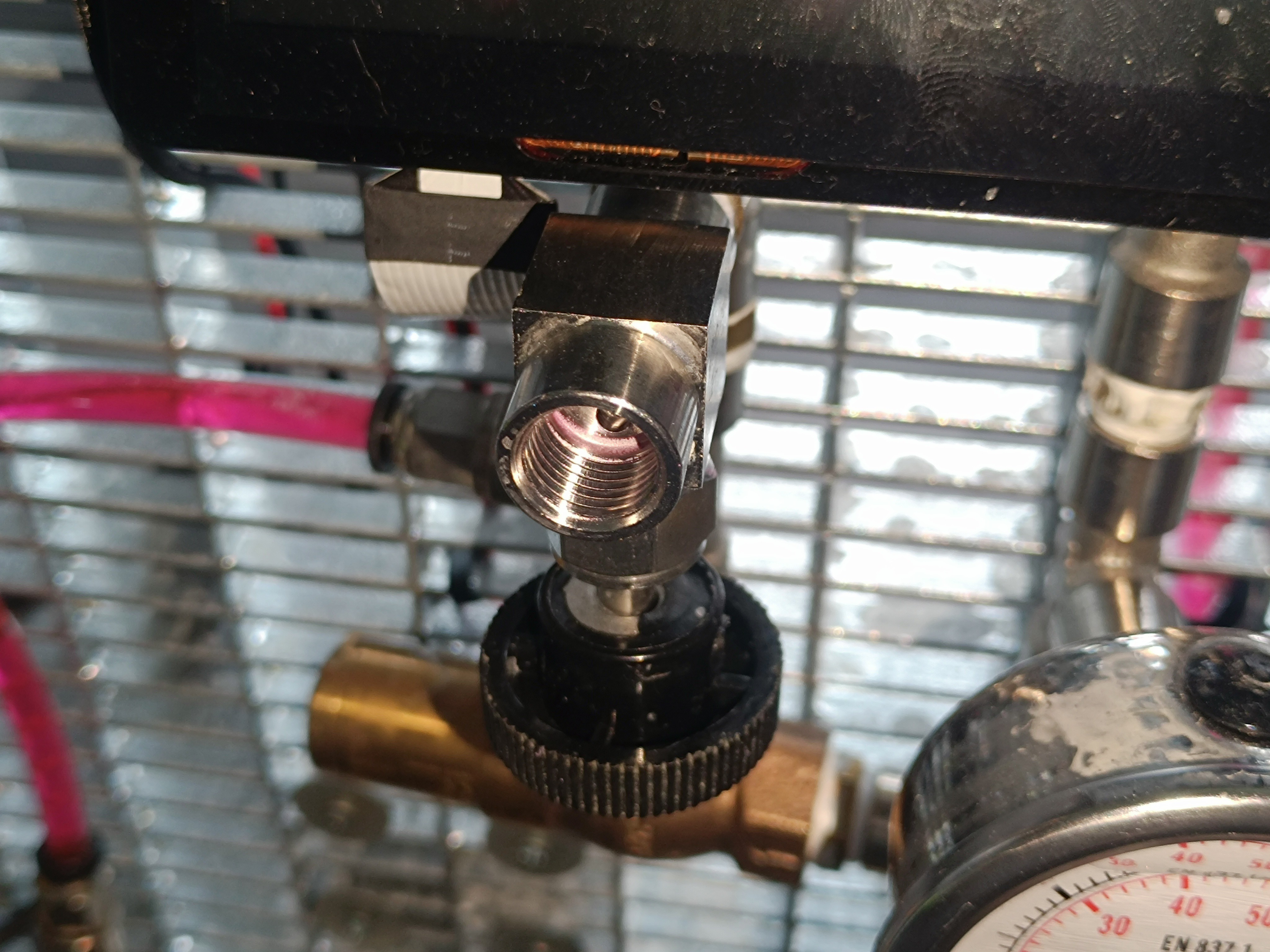
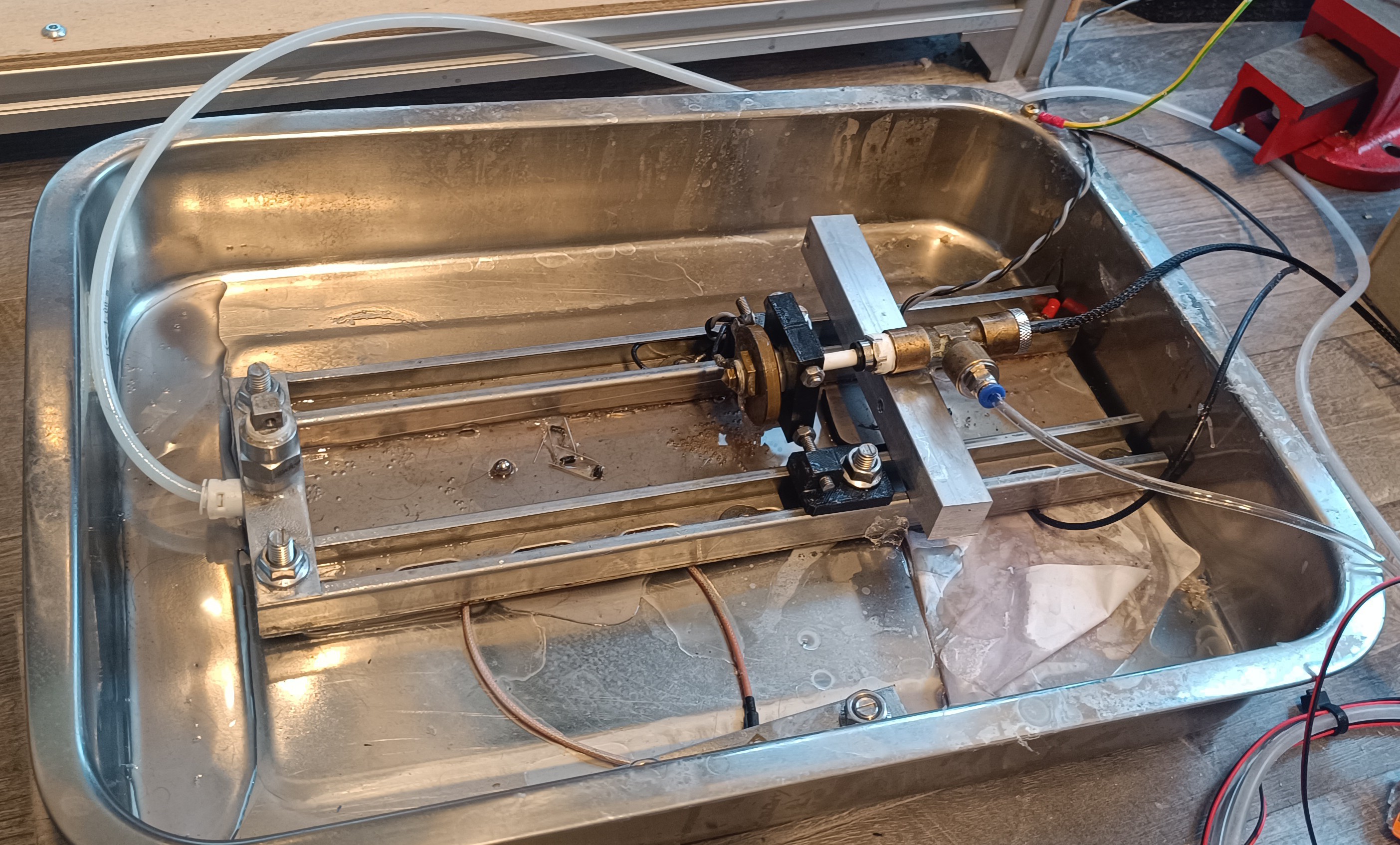
The ink is drawn from the tank into the pumps and is pumped into the high-pressure line. The system pressure is controlled by a relief valve which I set to around 50psi. The relief valve lets some of the ink flow back into the tank to keep the pressure steady.
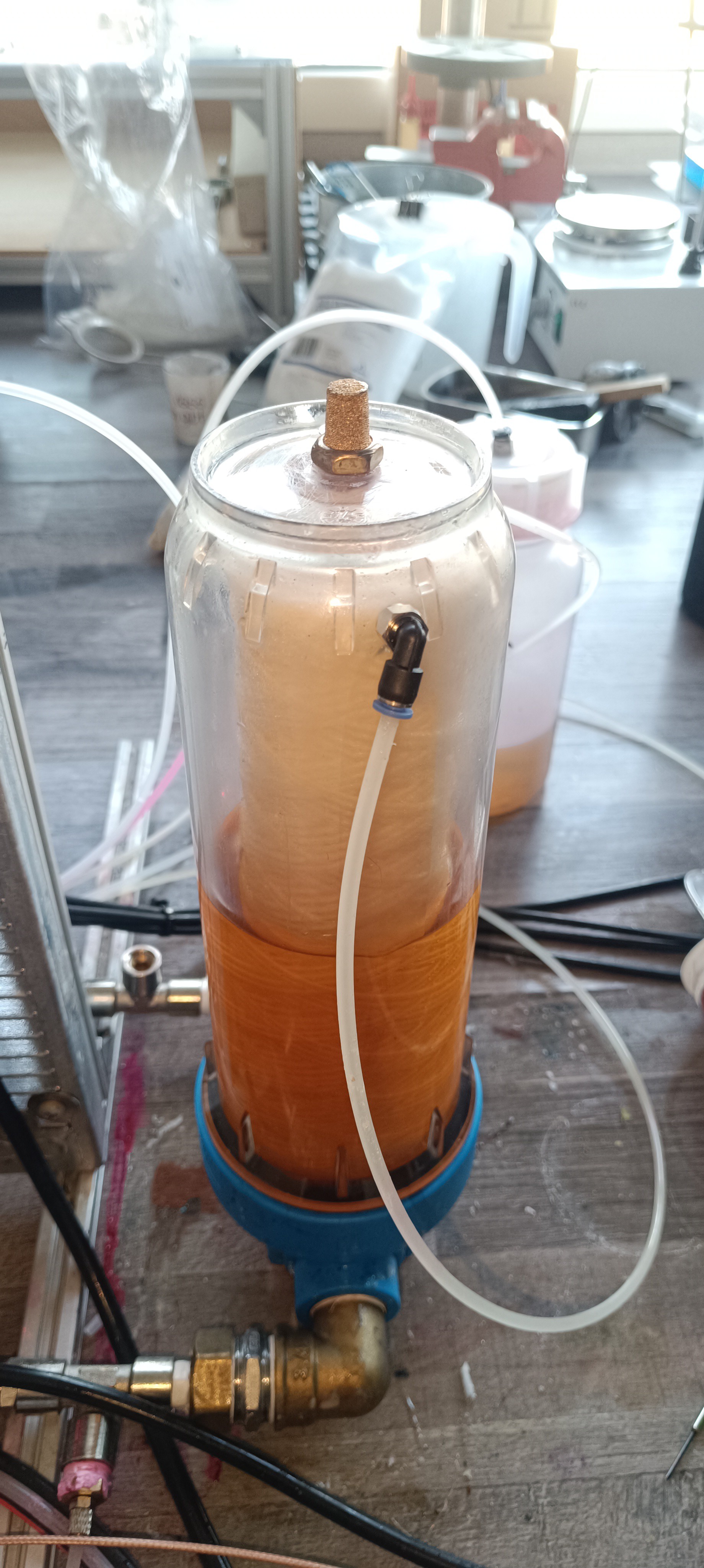
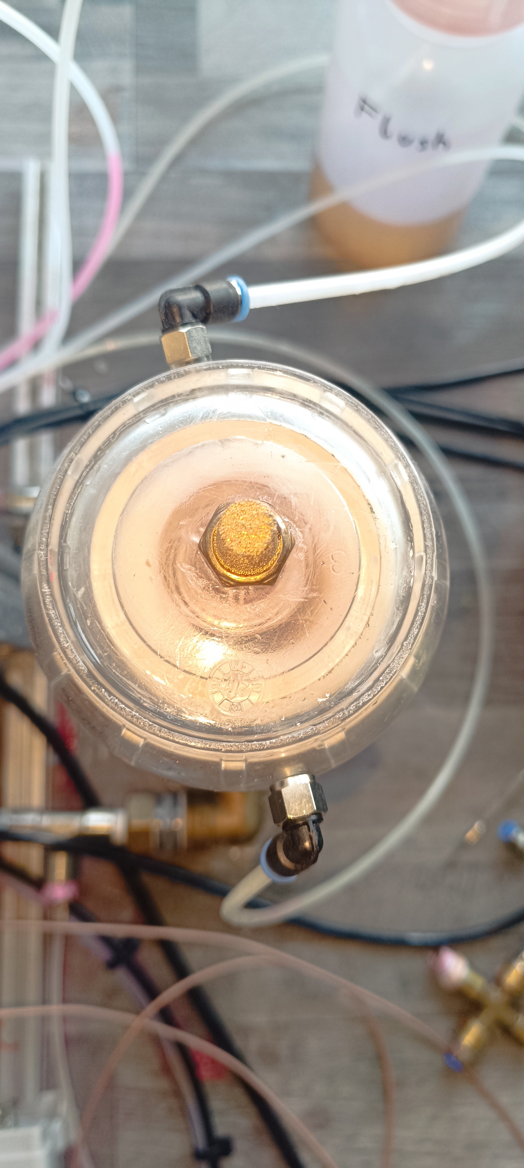
The pressurized ink flows through a pressure regulator that regulates it down to the desired ink pressure of the stream (eg. 40psi). After that, it flows into a pressure accumulation tank/damper (just a tank with a hollow rubber ball inside) for stabilizing the pressure.
The idea behind that is, that by keeping the system pressure at 50 psi and by using a damper on the 40 psi side, pressure fluctuations on the 50 psi side will not affect the 40 psi side as long as the pressure doesn't drop below 40 psi at some point.
Now, when the ink valve is open, the ink flows to the printhead into the nozzle for ejecting the ink stream that hits the gutter to close the cycle.
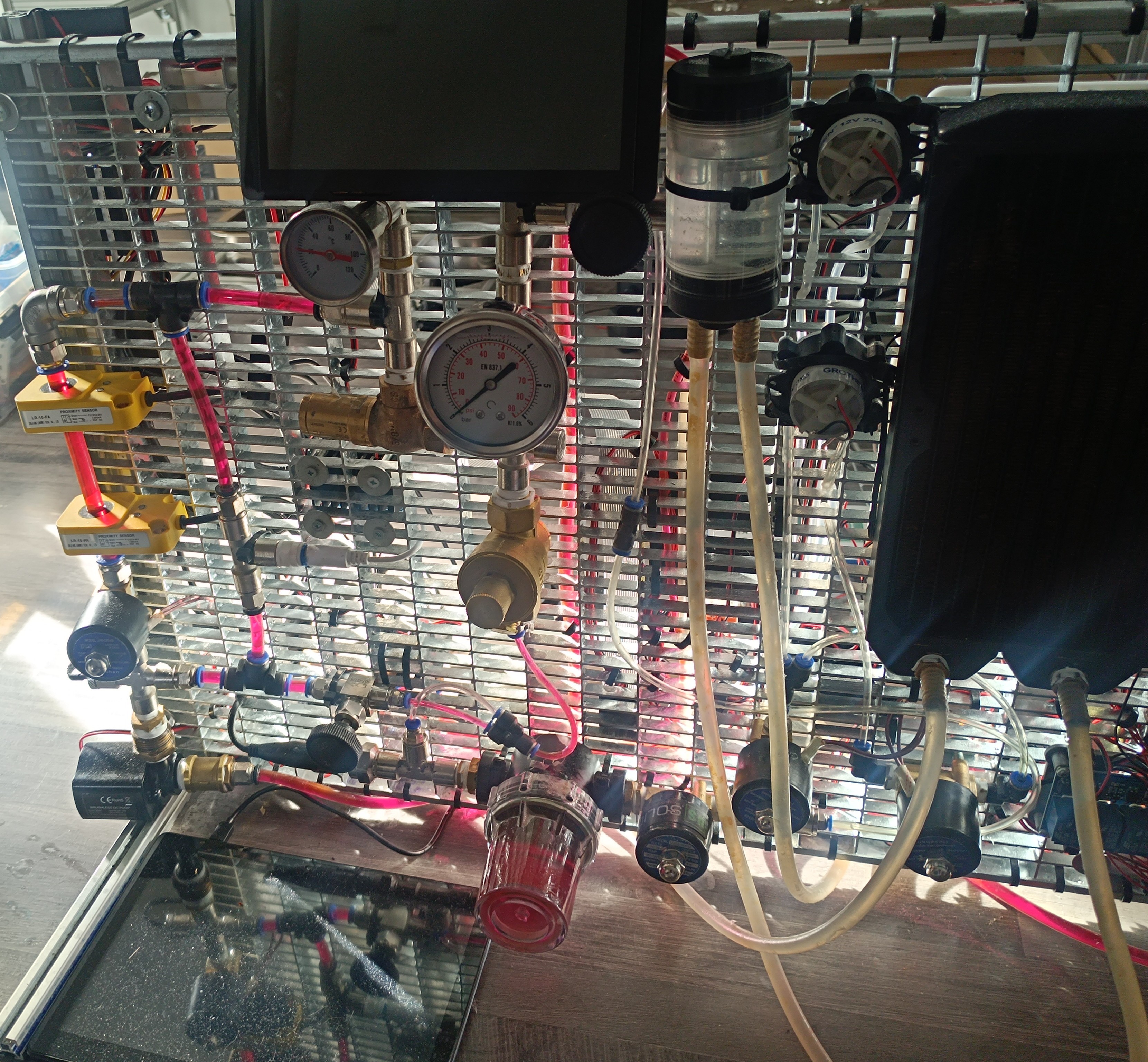
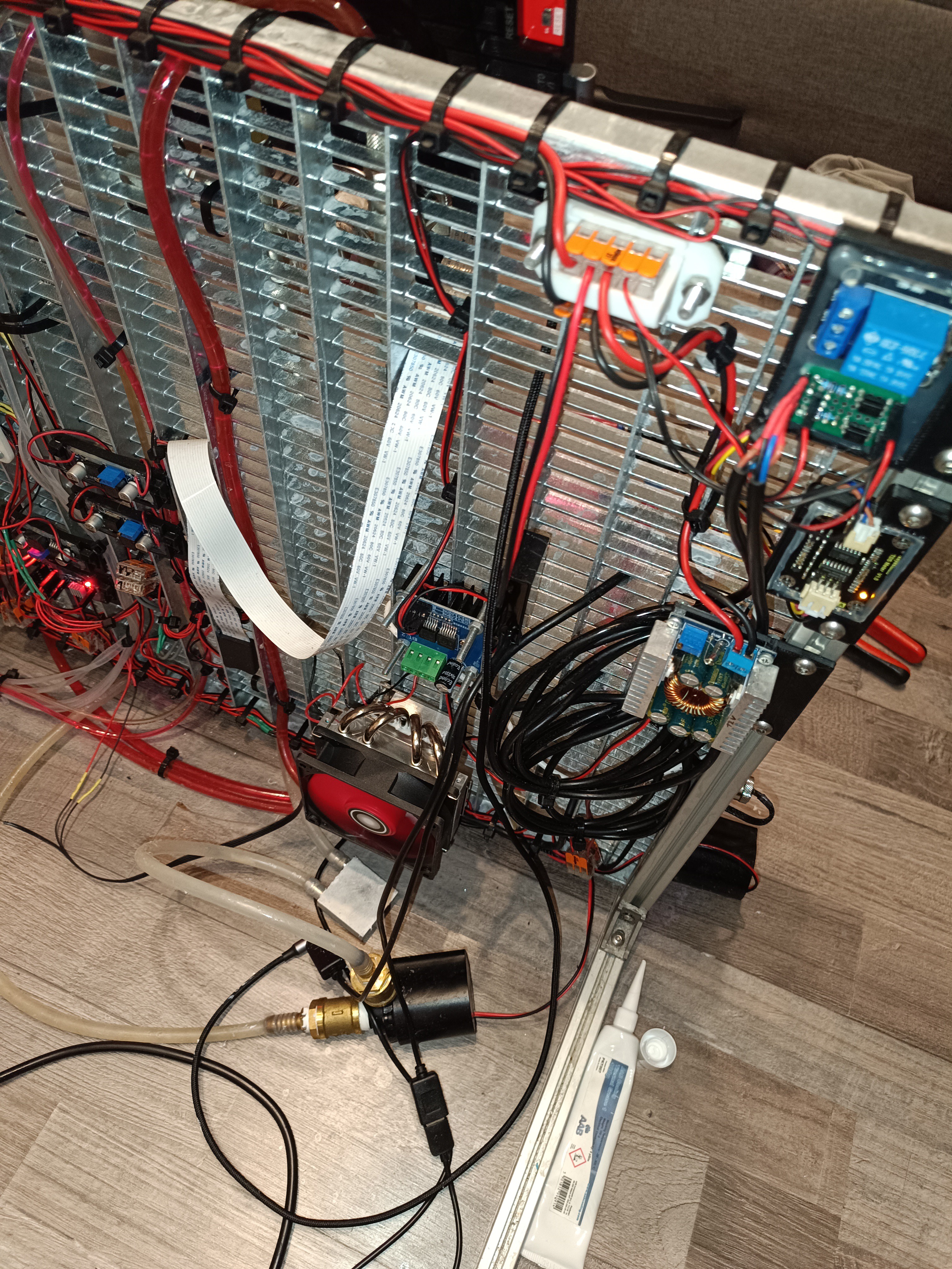
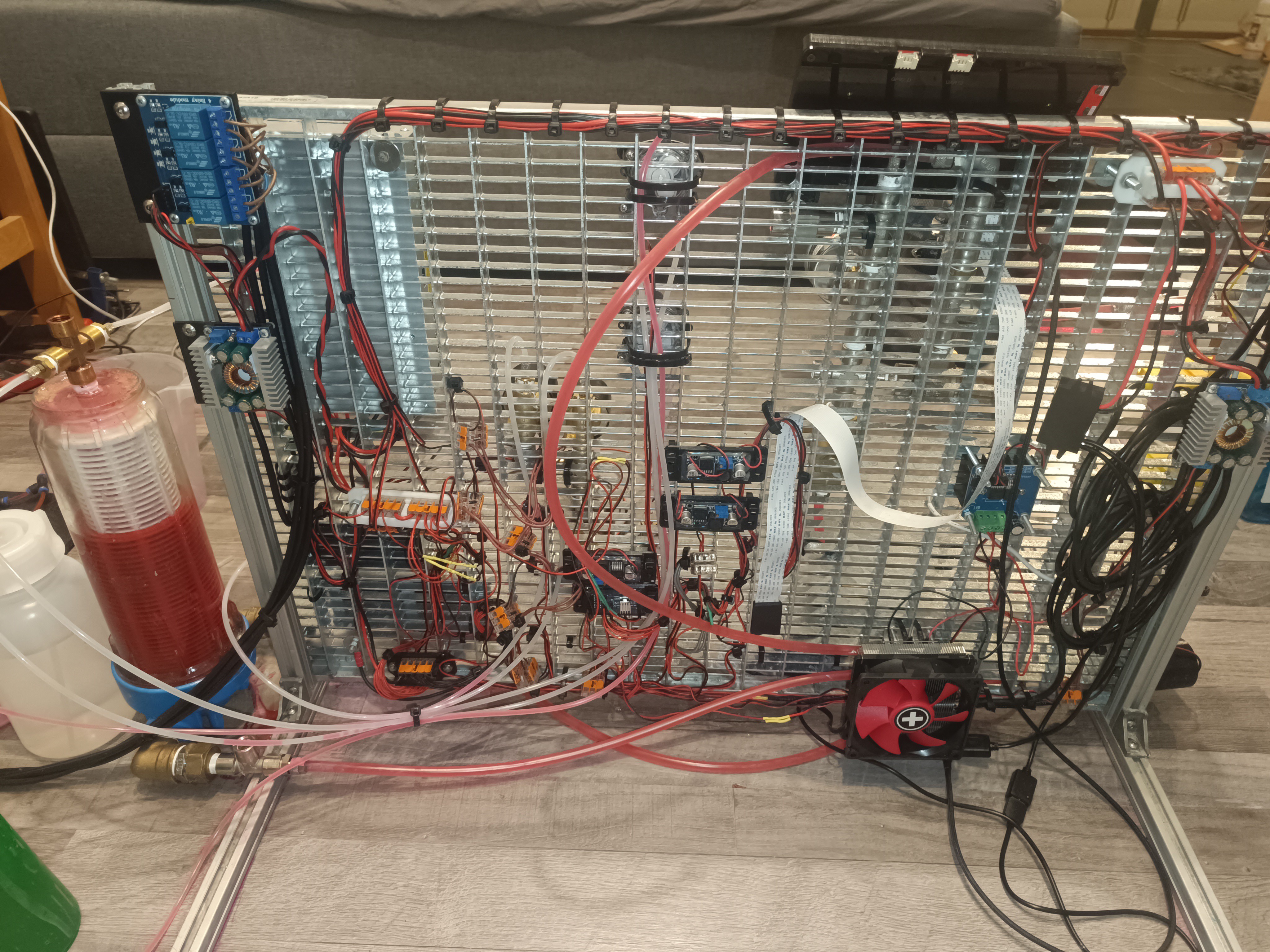
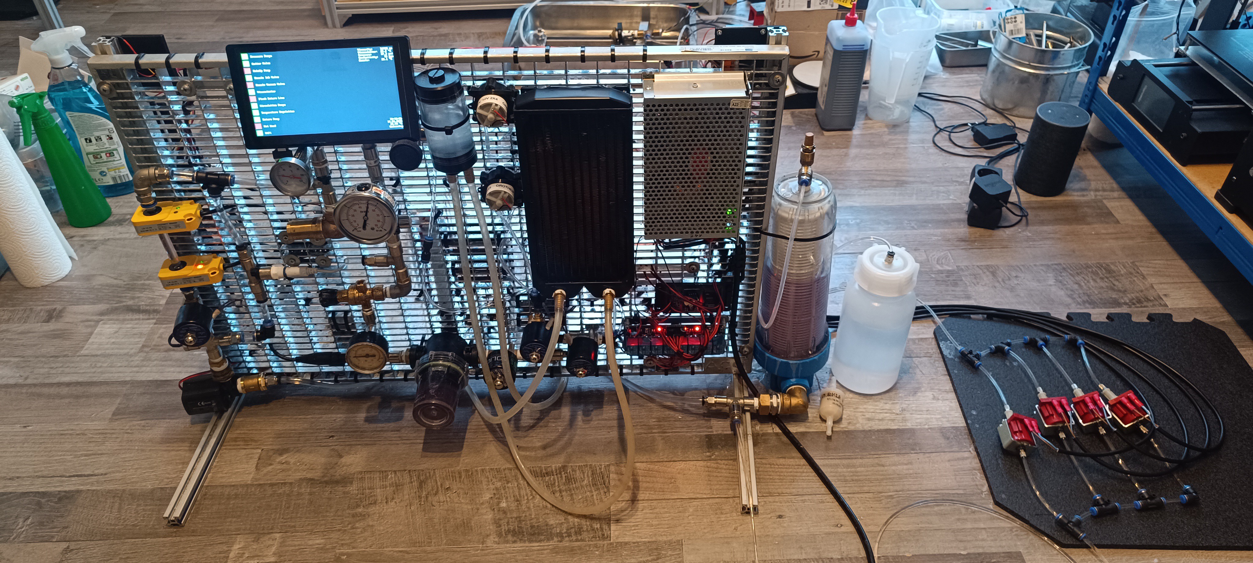
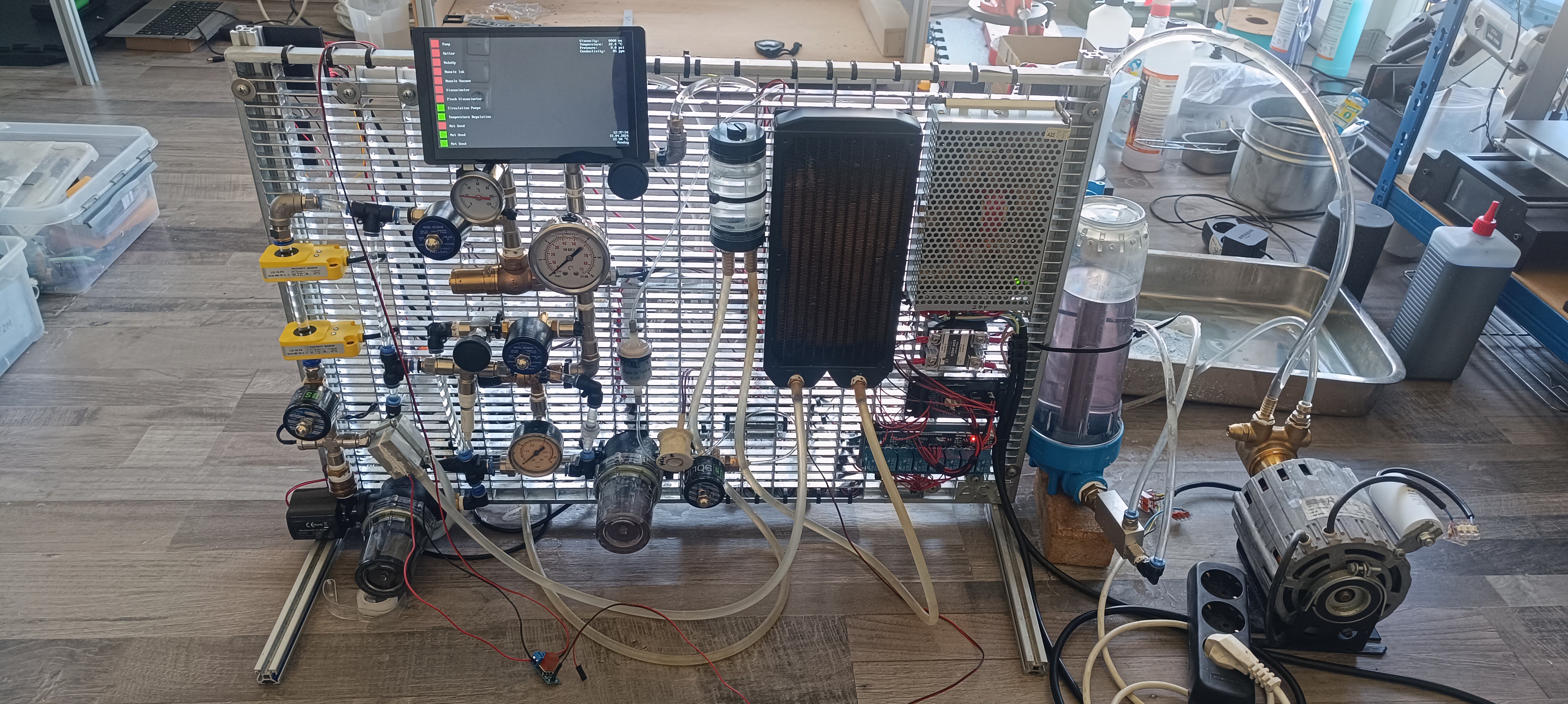
Back View of the Machine
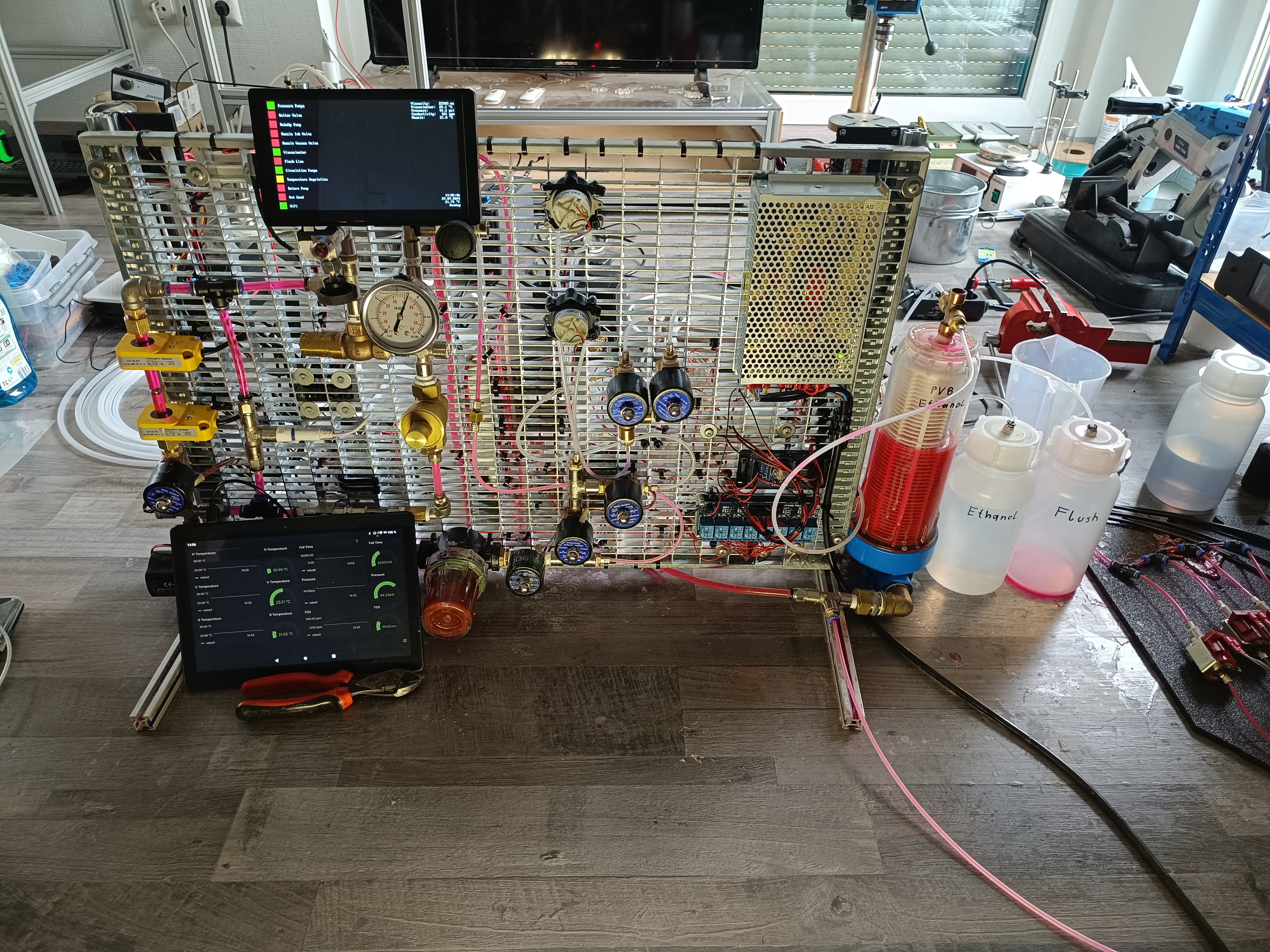
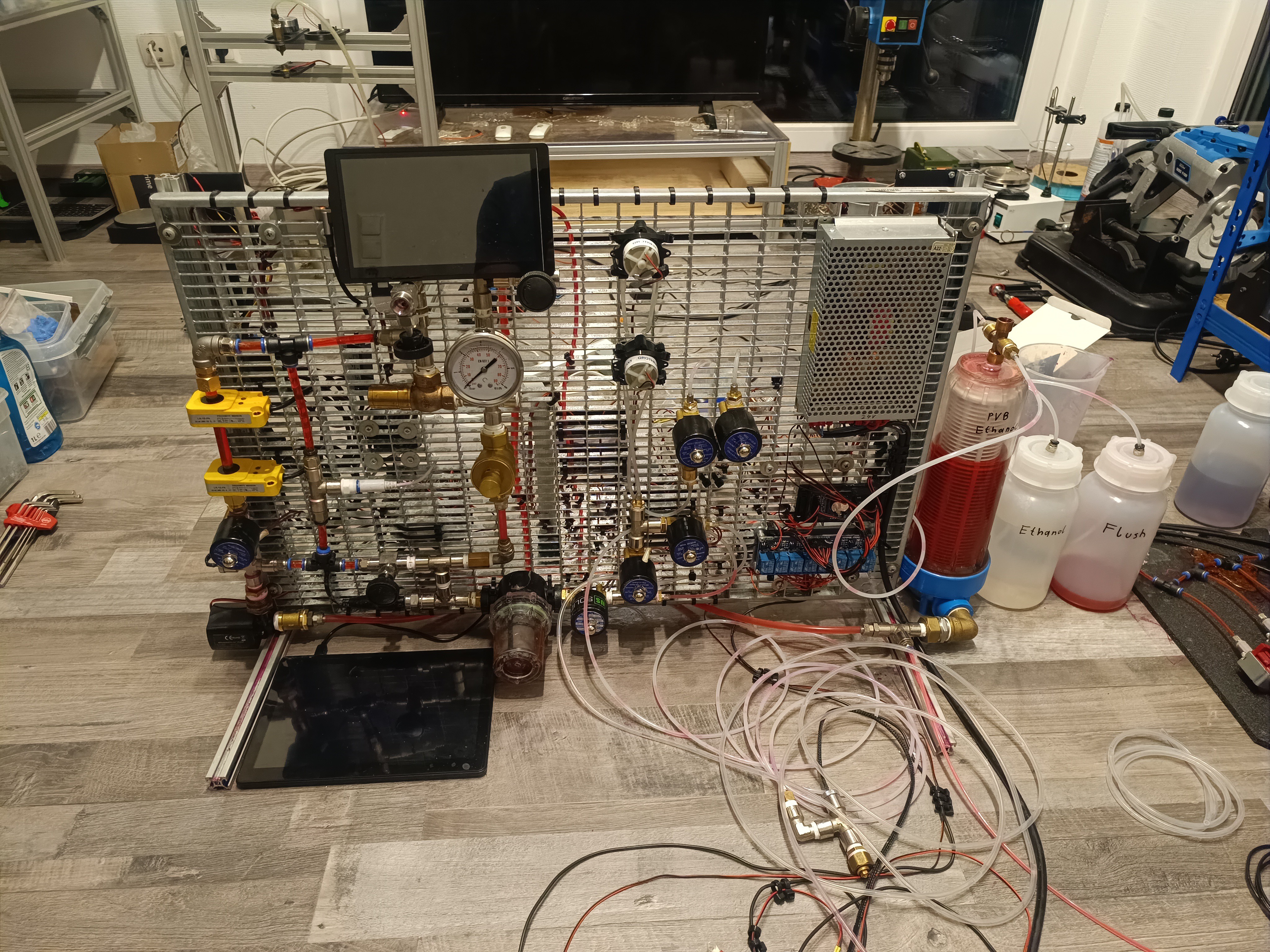
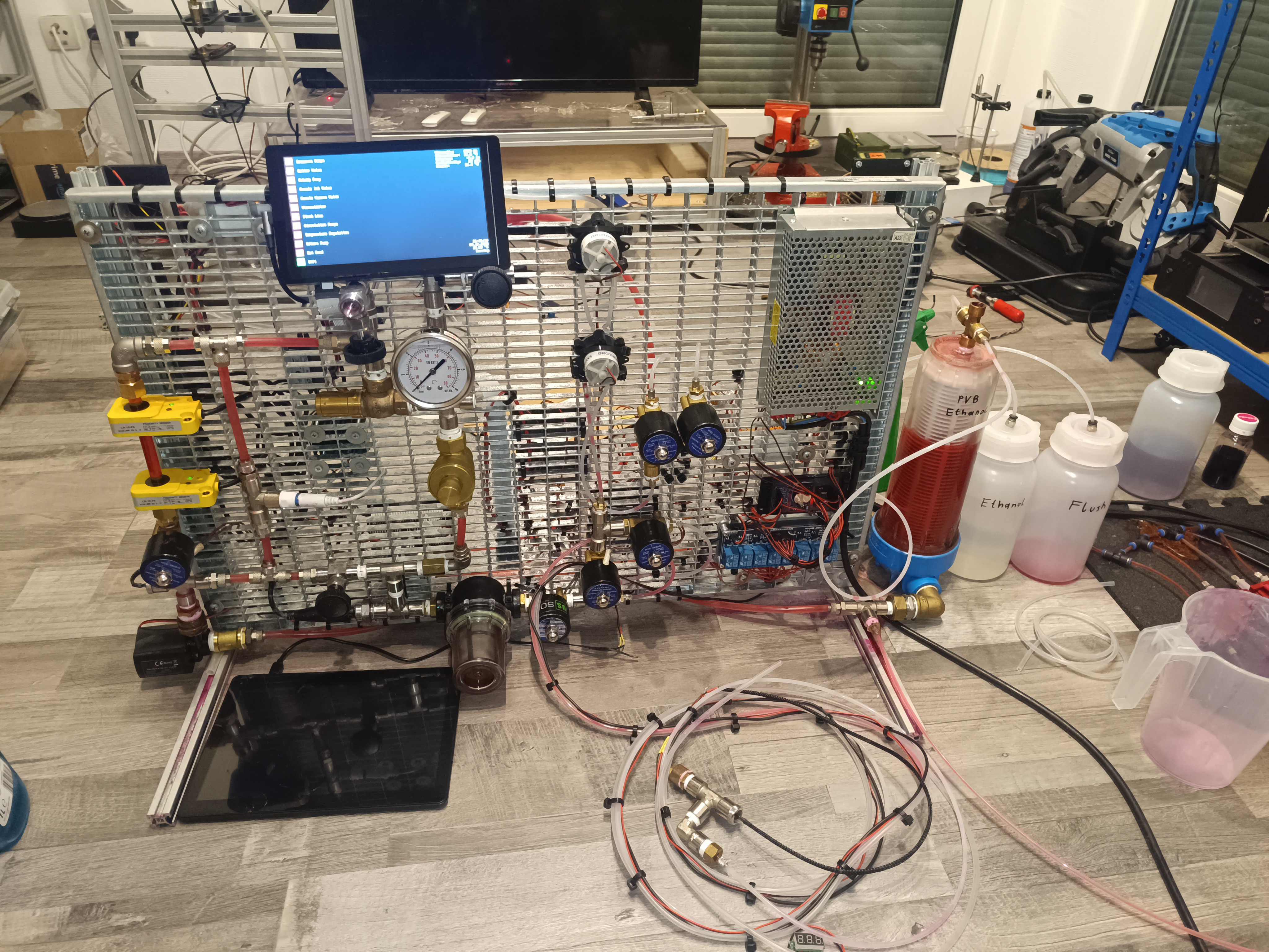
Front View of the Machine
Touch UI
Summary
At first, I thought using many small pumps instead of one large pump would add more complexity to the project, but it turned out to be the opposite, here's why:
One large Pump
I searched for a long time until I found the portafilter coffee machine rotary vane pump that could supply high pressure at a high flow rate. I bought a used one for cheap, but when you buy these pumps new, they can easily cost multiple 100€. The pump I used was also quite noisy and introduced a lot of heat into the system.
I bought this pump especially to power the venturi nozzle which injected a lot of air bubbles into the ink, leading to a buildup of foam, damage on the pump vanes over time, and air bubbles mixed into the ink stream.
In short - I had a lot of problems with this pump.
Before I started using the small pumps I searched for other types of large pumps like garden pumps, hydraulic pumps, high-pressure fuel pumps, and diaphragm pumps, but none of them could meet all of the requirements.
There are also special CIJ pumps available, but they are very expensive and hard to get.
Since this is a DIY project I think it would be very frustrating for others to start the BOM with a pump that is expensive, loud, and hard to get, so I looked for alternative ways.
Multiple small Pumps
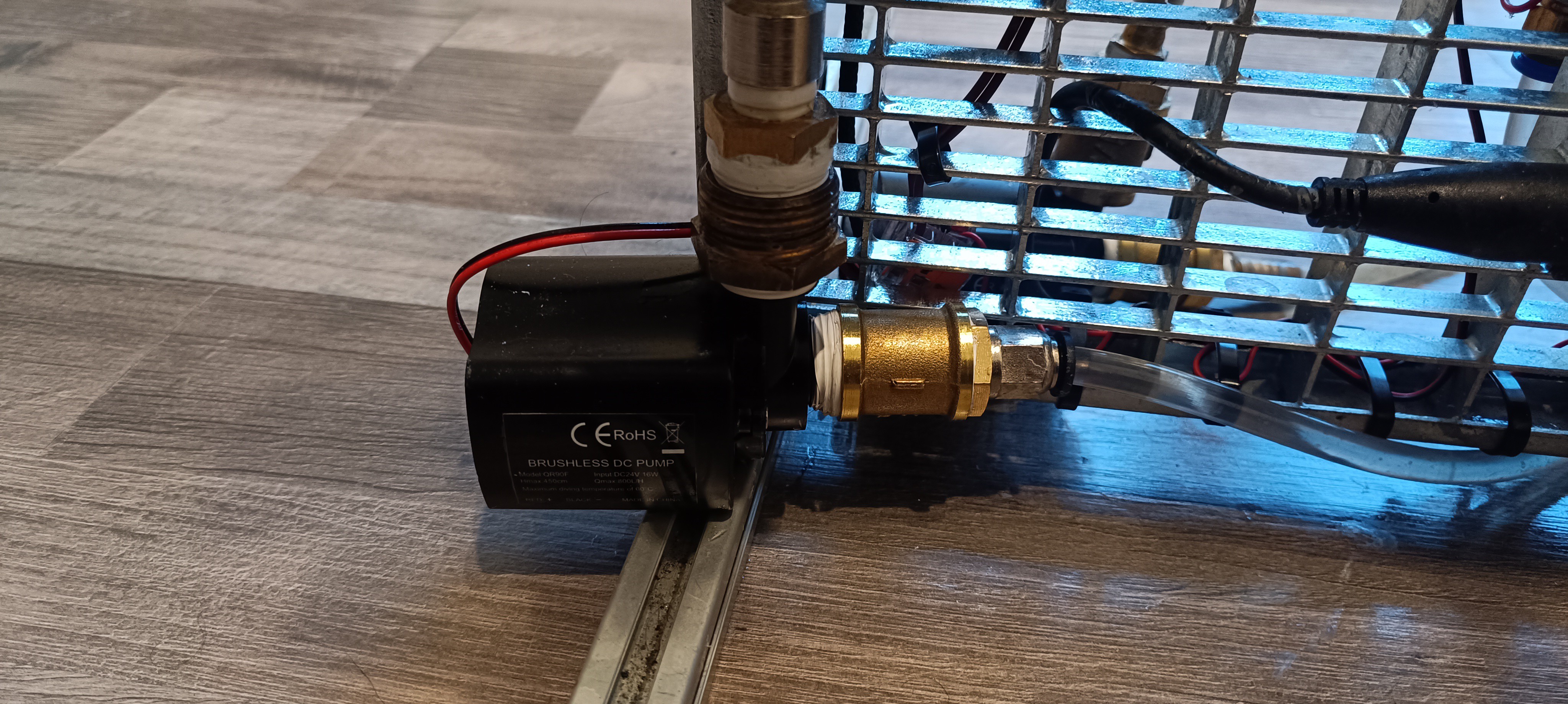
Brushless DC Pumps
I already started using the two brushless DC pumps for the new viscosimeter and later also used them for ink circulation. These pumps cost less than 30€ each and are relatively silent. There is also no special type required and it is possible to just use any pump that can provide enough flow and pressure to lift the steel ball inside the viscosimeter and circulate the ink.
Peristaltic Pumps
Same as for the brushless DC pumps, no special requirement, besides generating enough suction for drawing the ink and makeup to the tank. The pumps I used cost less than 30€ each, but any other peristaltic pump should work as well. They also are relatively silent.
Solenoid Pumps
The only requirement for these pumps is being able to supply the needed pressure (eg. 50 psi).
I used 4 small and silent ones which did not cost more than 20€ each, but if you can find a model that has a 100% duty cycle while providing enough pressure and having an acceptable noise level, you could also go with just one pump. The noise of the models I use is very low so it's sometimes hard to see if they are running without taking a look at the pressure gauge.
By replacing the large pumps with the small ones, the noise of the machine could be reduced so much that it is now more silent than my 3D printer. With that, running it at any time of the day including deep at night should no longer be a problem.
Conclusion
In my opinion, using different pump types for different tasks instead of just one pump type for everything makes a lot of things easier. It will be easier to find the right pumps for the project and if one pump should fail, you would just have to repair or replace this cheap (eg. 30€) pump instead of buying a new multi 100€ pump.
Thank you for your interest in my Projects
Great thanks to @Paulo Campos and Robert for helping me a lot with this project :)
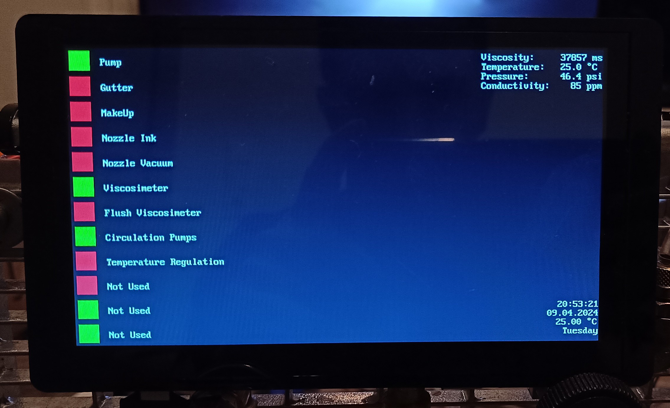
Here are some pictures of the 7-inch ESP32 powered control touchscreen and the latest changes to the prototype:
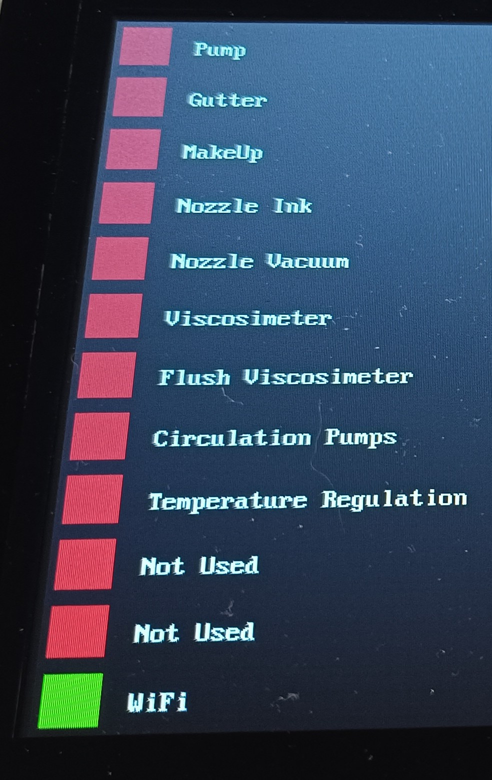
The squares on the left are touch buttons for the printer functions and on the right, you can see the sensor data on the top and the current time, date, day, and room temperature on the bottom.
ESP32 LCD Touchscreen
Since the display has no IO pins, I reassigned the 4 pins that were used for the micro SD card to use 2 of them for I2C (SCL and SDA) and the other two for PWM.
To access the pins I soldered wires to a micro SD extension flat-band cable.
Micro SD "Adapter"
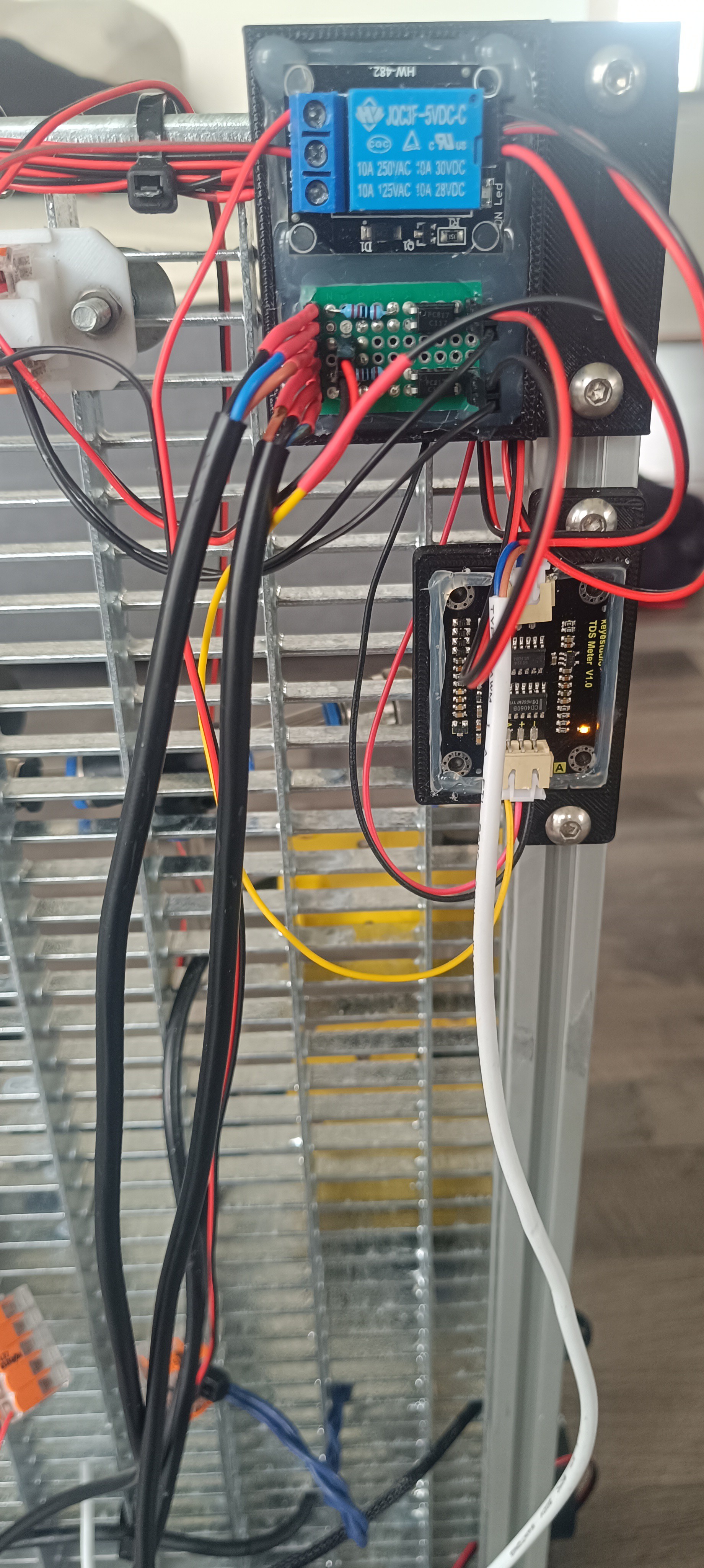
Connected via I2C are a DS3231 real-time clock, an ADS1115 ADC, and an MCP23017 IO extension.
ADS1115, DS3231, MCP23017 and 8Ch Relay Module
- The MCP23017 is used for switching the relays and valves and reading the inductive sensors of the viscosimeter.
- The ADS1115 is used for reading the analog voltage of the pressure, conductivity, and temperature sensors.
- The DS3231 is used to keep track of the time and measure the room temperature.
3.3V/5V logic level converter and AMS1117
The touchscreen is powered by an AMS1117 3.3V regulator.
While the ESP32 is running well on 3.3V the LCD seems to need a higher voltage since it's flickering a bit when powered by 3.3V which doesn't happen when powered by its USB-C connection.
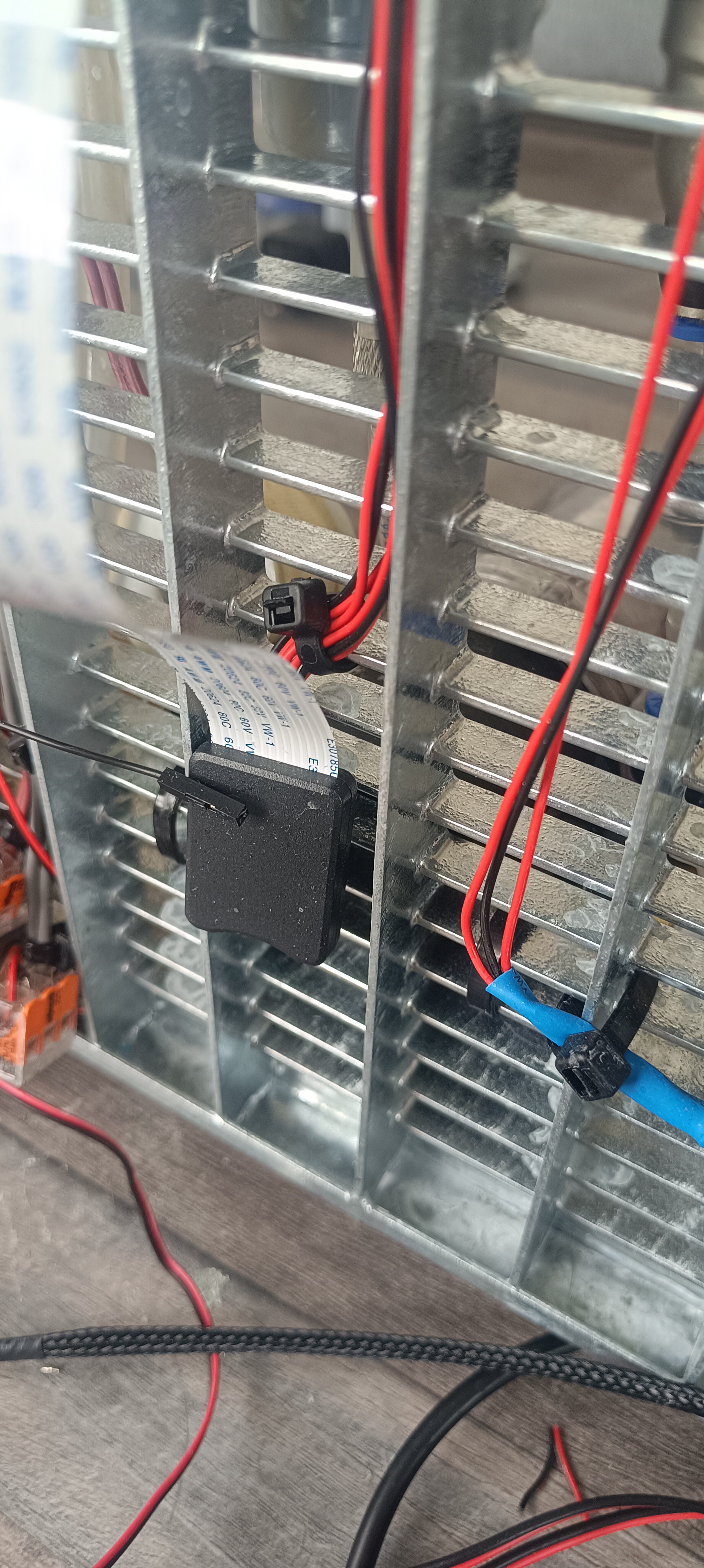
To get rid of the heat from the Peltier module I added a dual-fan radiator, with the fans pointing toward the grid frame of the machine.
Backside of the RadiatorFront View of the Machine
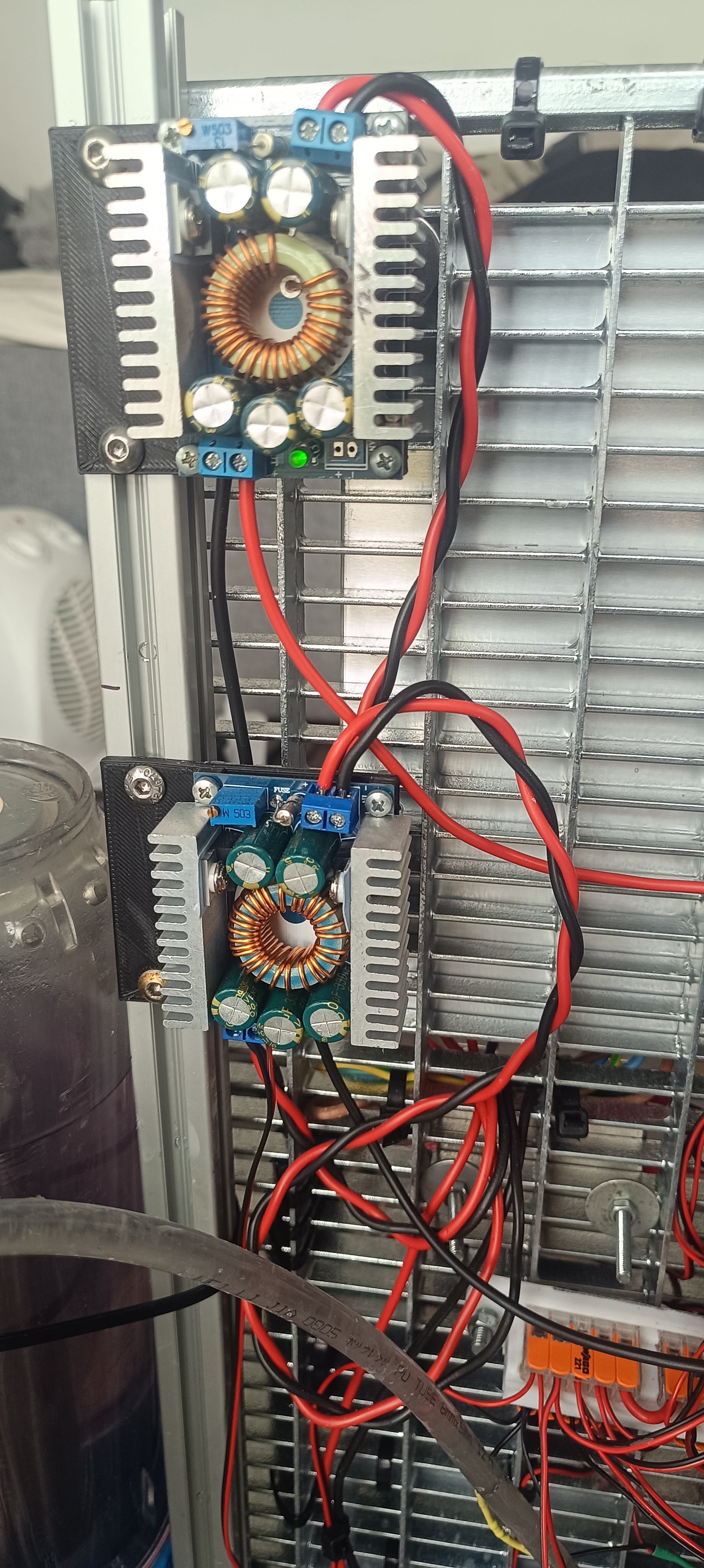
Currently, I'm using two XL4016 step-down converters for converting 24V from the power supply to 5V and 12V.
While the 5V is used for powering the I2C devices and sensors, the 12V is used for the Peltier module and viscosimeter valve.
XL4016 for 12V and 5V
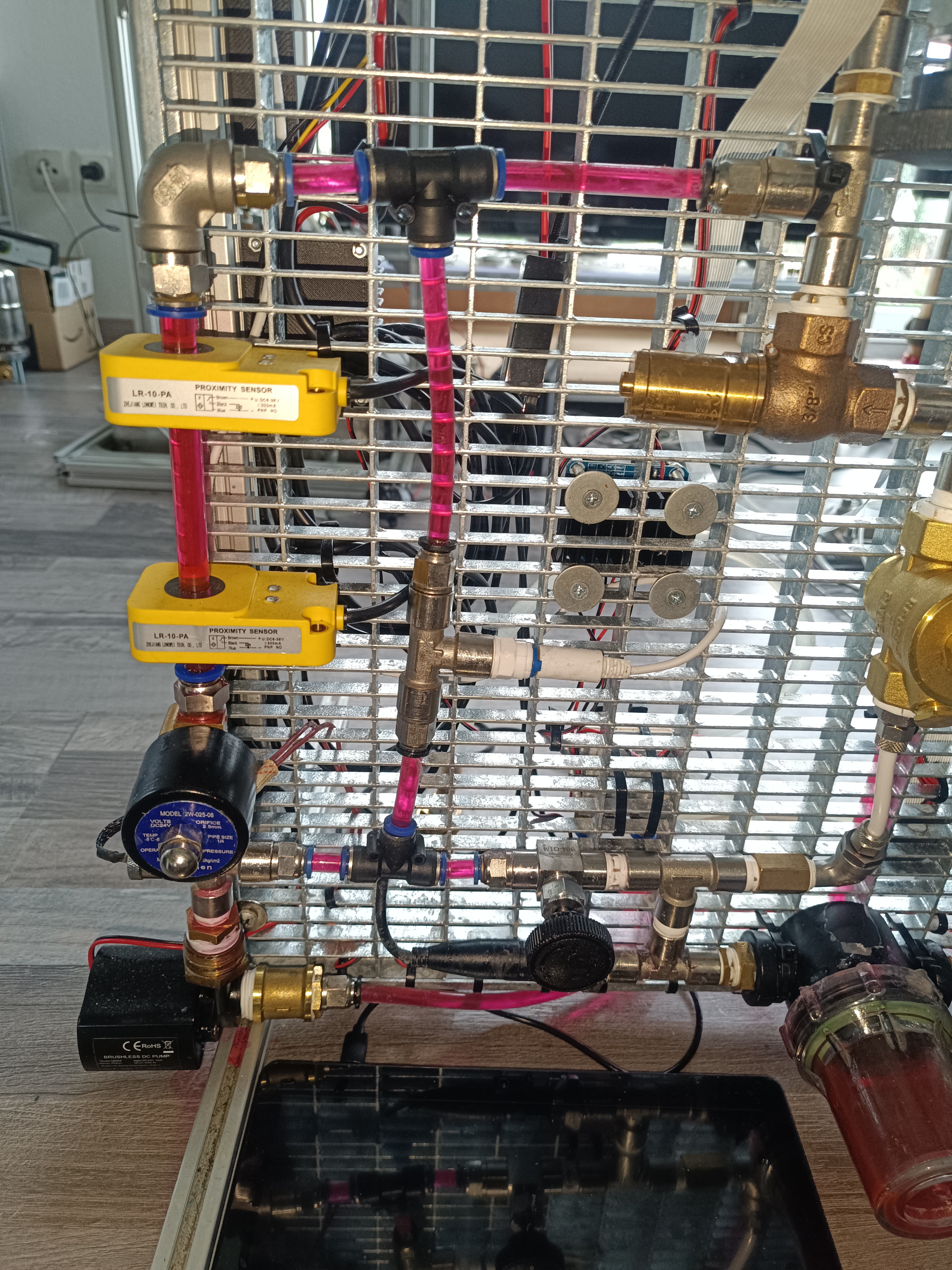
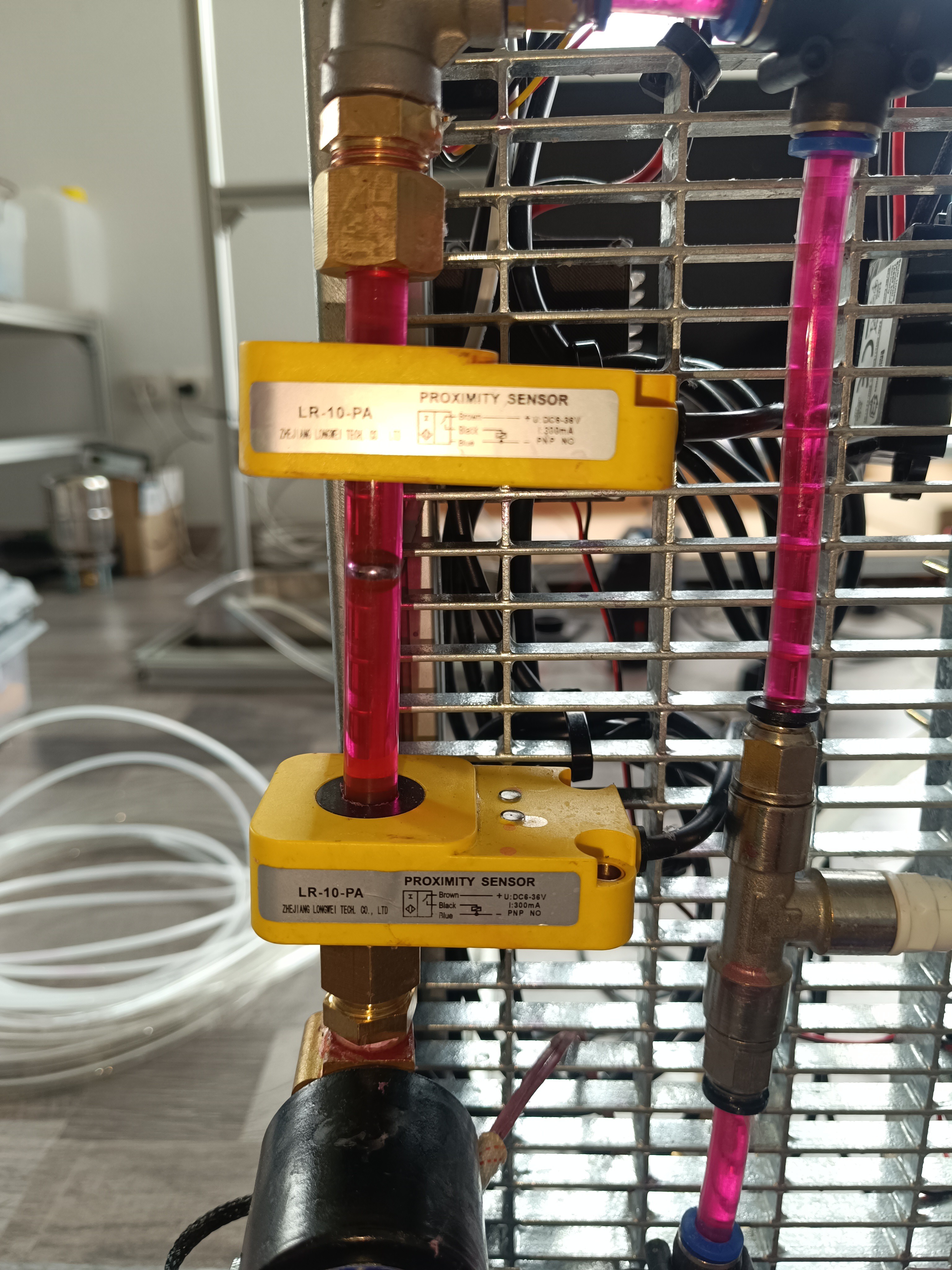
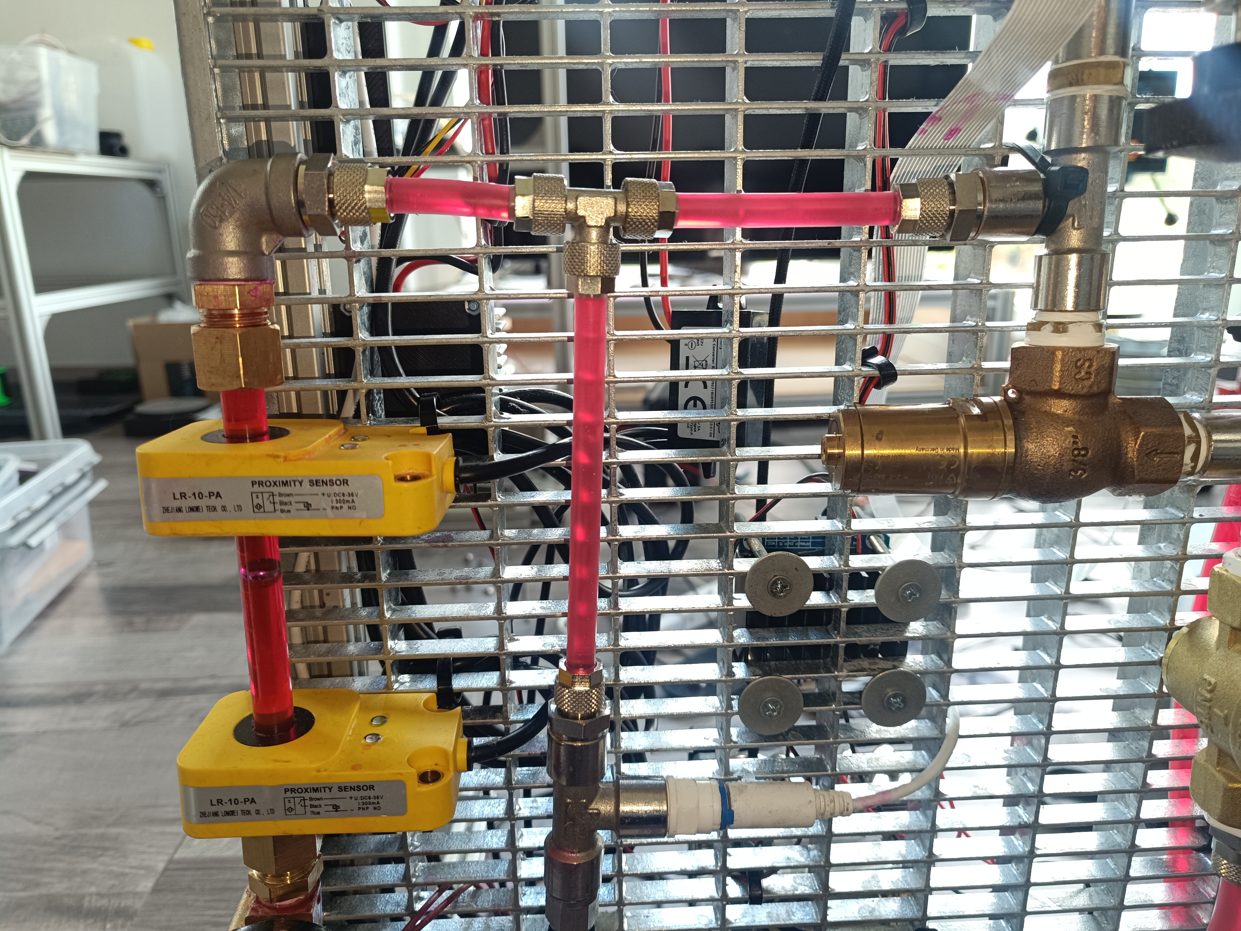
A single relay module is used to open the valve for lifting the 8mm steel ball inside the viscosimeter. The falling steel ball gets detected by 2 inductive sensors.
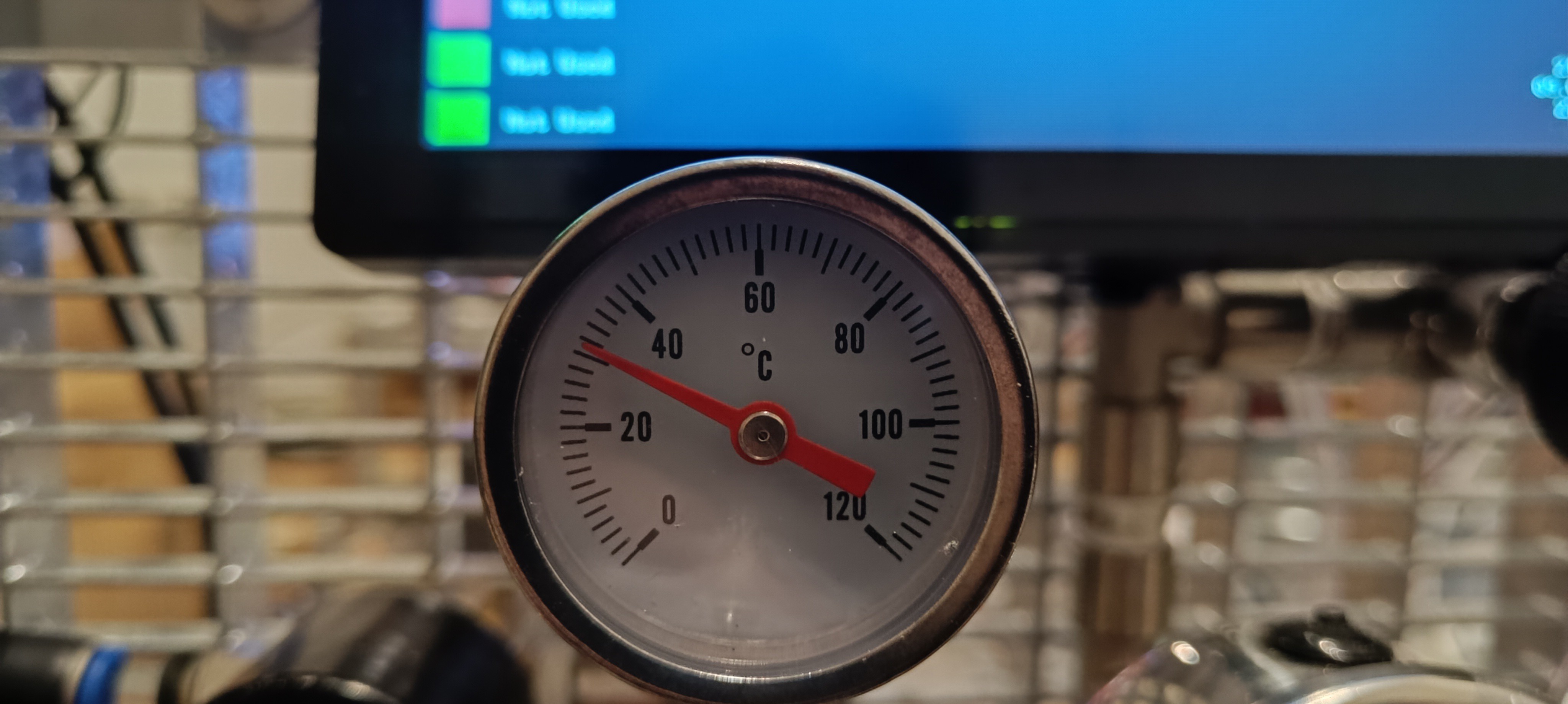
For the viscosimeter, I used a clear polycarbonate pipe with a 10x8mm diameter and 150mm length. The distance between the two sensors is 60mm.
New Viscosimeter with Peltier Module and Circulation PumpThermometer on the Main Ink Cycle
I used a dual MOSFET module for switching the 12706 Peltier module with a 1kHz PWM signal.
Dual MOSFET Module
The Peltier model draws around 50W during testing and the MOSFET module gets very hot without cooling so I will likely place the MOSFET modules for both Peltier modules next to each other and add a small silent 40mm fan for cooling.
Peltier Module
Together with the pump that pumps the ink around inside the viscosimeter and also heats it up, a thermistor in the cross-fitting, and some PID code, the temperature of the ink inside the viscosimeter can be kept constant without oscillation.
In the future, I will add some code to flush the viscosimeter from time to time with fresh ink to check if the viscosity has changed and automatically add solvent if the viscosity has risen too high because of solvent evaporation.
For flushing, the viscosimeter is connected to the main ink cycle by two valves that can be opened to let fresh ink flow through the viscosimeter while the pump is running and the measuring pipe's valve is opened to flush all the old ink out.
LCD with Wifi Connection IndicatorFor the next update I'm planning to add a data logging feature to write all sensor readings and machine function states together with a timestamp to a file on an FTP server to make it possible to analyze every test run and see what changes in the sensor readings follow the performed action.
I think this will add a lot of value to the machine since it makes the testing results more comparable and will provide a way to share the collected data besides recording videos and taking pictures. In the best case, it would be possible to display the sensor readings as graph lines and have a way to see which machine function was active at a time, e.g. to see that the viscosity decreases with a temperature rise or that the pressure drops when the ink valve is opened and so on.
 Dominik Meffert


 ,
,
 Depending on the pressure, the jet velocity changed and, with it, the position of the breakup point and also if there were satellite droplets.