David H Haffner Sr
-
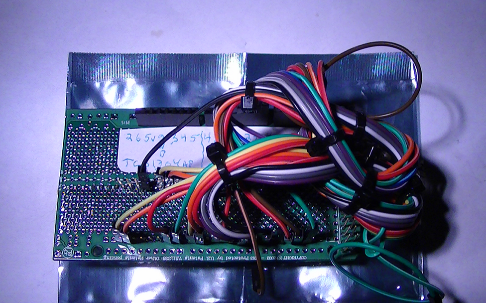
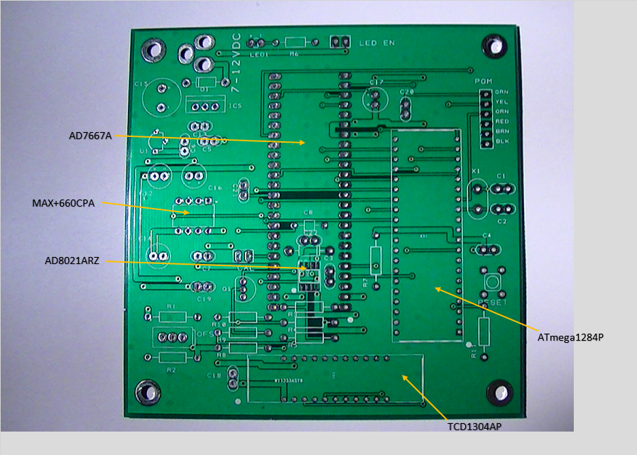
Boards Are In For The TCD1304AP Circuit Driver :)
04/05/2017 at 19:37 • 0 commentsWell the boards are in, compliments of David Allmon. This project has been able to move along at a great pace, thanks to his invaluable help and suggestions...many props to him!
Here are 2 views, the 1st view below is the front face:
![]()
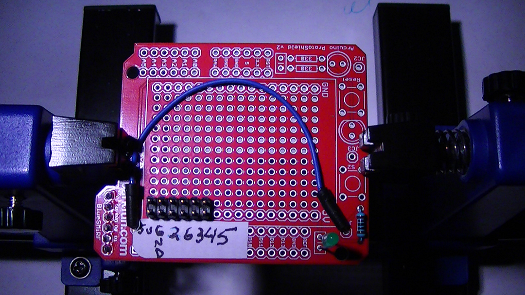
Next view is the back face:
![]()
-
SW 1 (switch function test) For The TCD1304DG CCD Success...
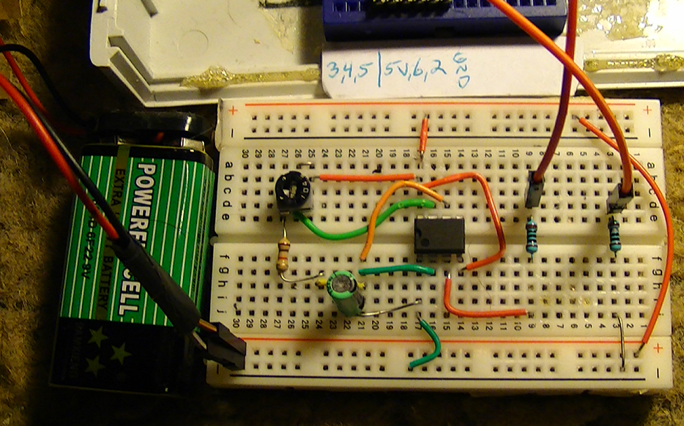
04/02/2017 at 17:39 • 0 commentsYes, I mentioned the TCD1304DG CCD chip, why? I fried the TCD1304AP. It was working for awhile, and then...Blewy,,,,,,,,,*#@$ (this was the main reason for never posting any results :( )
This is the main reason for taking some time and making this pulse generator test circuit, simple but effective, working with David Allmon is incredible, one smart cookie :) I am using his newest design from his website with a few necessary mods of my own, so it fits and operates within the parameters of the Raman spectrometer.
The C code remains the same, no changes their, except for my own so I can build a custom interface with MegunoLinkPro for capturing the spectral data and choosing things like dark counts and wavelength ranges.
So the first test I ran was making sure the Push button switch functions correctly and I found no need for a switch debouncer (I think, plot looks good at rise time with no ringing when switch is depressed.)
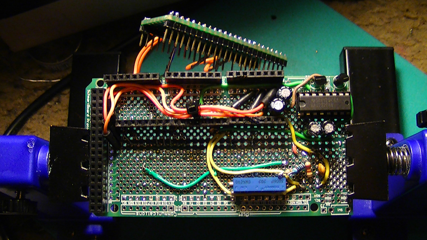
![]() At the center of the plot you see where the switch gets depressed in order to send data from the buffer at the MCU, I see no "ringing" at rise time so it looks like the raw data should be ok.
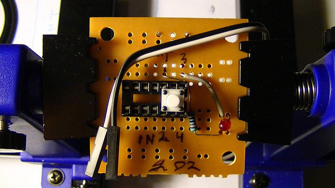
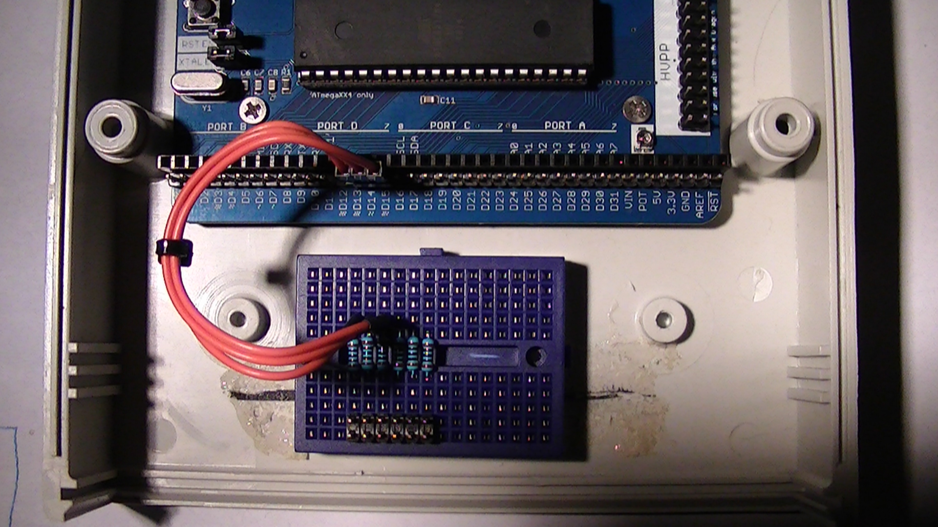
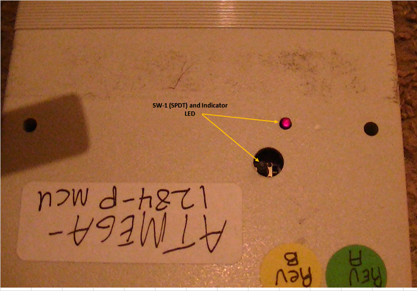
At the center of the plot you see where the switch gets depressed in order to send data from the buffer at the MCU, I see no "ringing" at rise time so it looks like the raw data should be ok.![]() Here you see how I have the switch and indicator LED set up at the MCU, the LED is normally off, and will light up as soon as data fills the buffer (first science frame,) depress the switch and data is sent, the next science frame gets loaded into the buffer, and so forth...
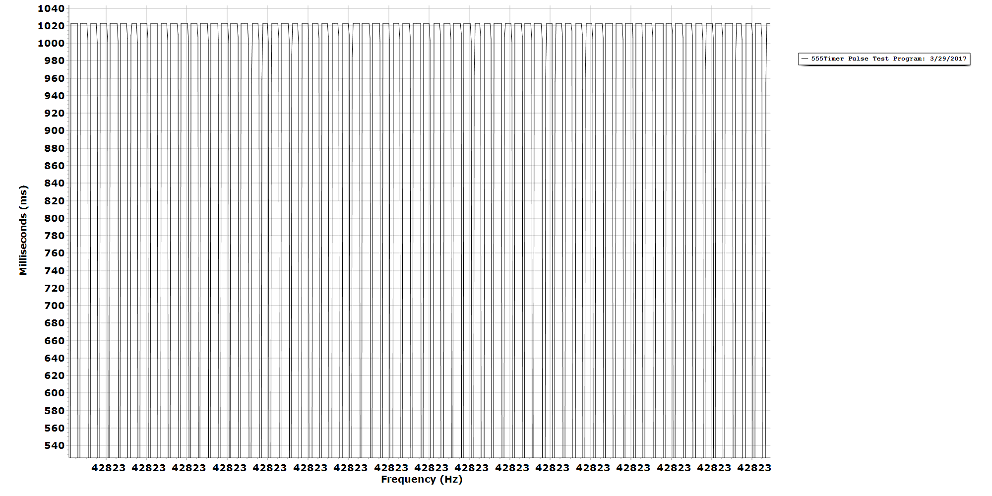
Here you see how I have the switch and indicator LED set up at the MCU, the LED is normally off, and will light up as soon as data fills the buffer (first science frame,) depress the switch and data is sent, the next science frame gets loaded into the buffer, and so forth...![]() These are the other waveforms I have fiddled with from my test circuit and they work pretty good, I don't have an oscilloscope and I cannot afford one, so I like to improvise on the cheap...hey it works.
These are the other waveforms I have fiddled with from my test circuit and they work pretty good, I don't have an oscilloscope and I cannot afford one, so I like to improvise on the cheap...hey it works.The C code for the CCD firmware takes only 42% program memory, and the ATmega1284P has 130,000 bytes of flash memory for video, so I have some good breathing room for the extra code for the MegunoLinkPro interface portion.
-
*Update* Trying to Tweak The 555 Pulse Generator Test circuit...
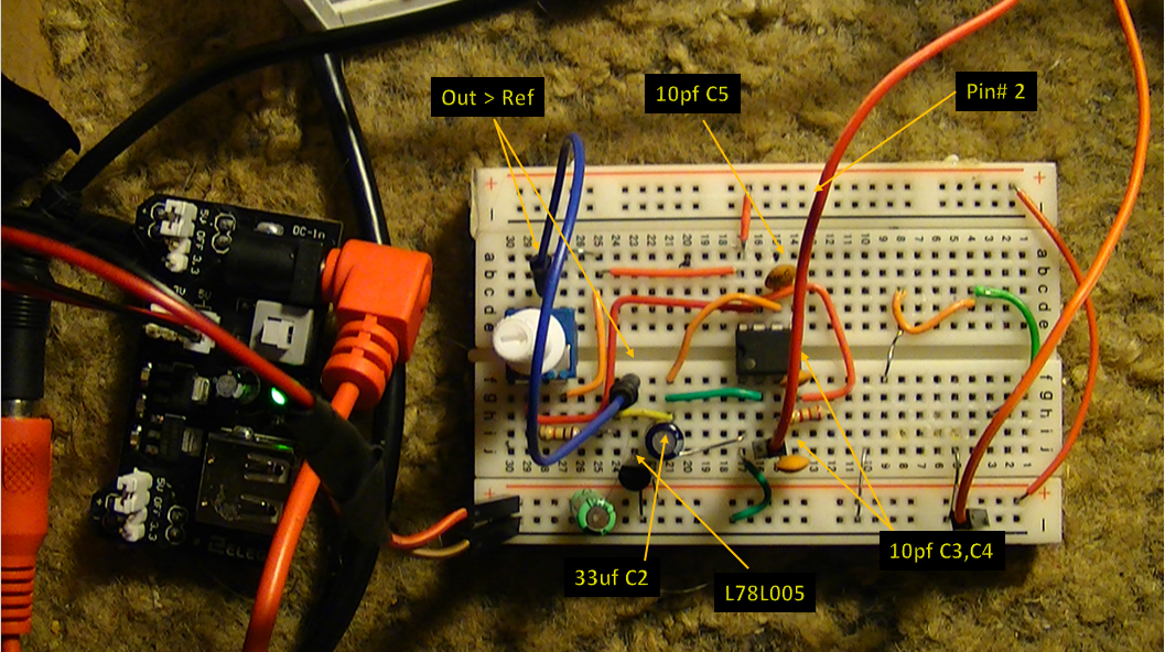
04/01/2017 at 20:50 • 0 commentsI added a couple of 10pf caps to a few pins to reduce some noise and placed an L78L05 voltage regulator inline with power coming in, because it helps with reducing noise and keeps voltage at Ref VR1 constant.
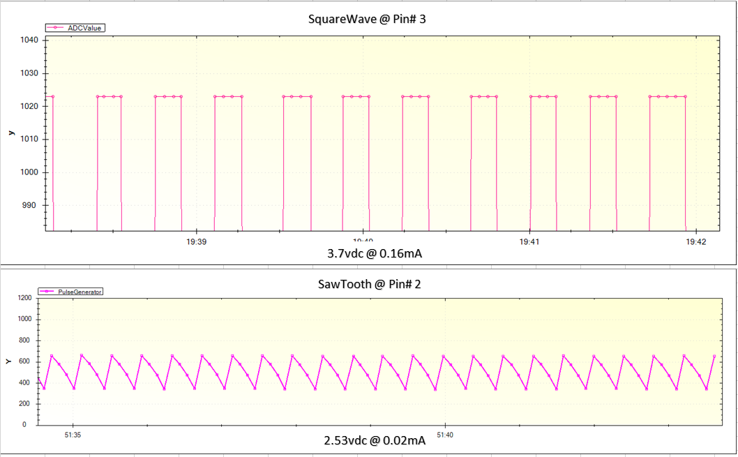
So, I experimented with this and found I can get a sawtooth wave from pin # 2 on the 555 timer chip @ 2.53vdc at 0.02mA
![]()
![]()
-
*UPDATE* Better Pulse Generator Circuit Tester...
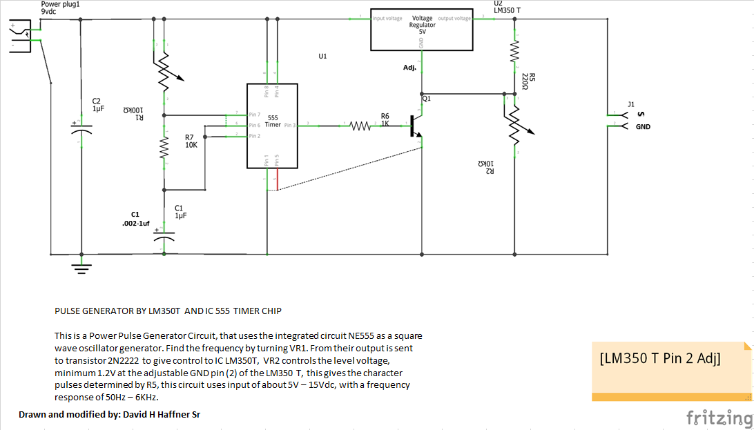
03/31/2017 at 20:50 • 0 commentsI needed a more reliable pulse generator to test out certain aspects of the CCD detector and found the one that I'm posting the schematics that I drew up on it below. I ordered the PCB for this one, so it will be a more stable circuit with hopefully no ringing.
*Q1 is a 2n2222*
![]()
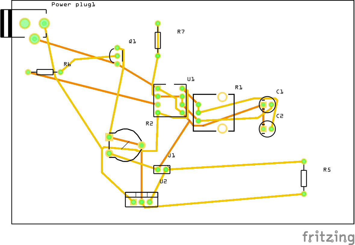
Below are the PCB designs:
Above view
![]()
Bottom view
![]()
-
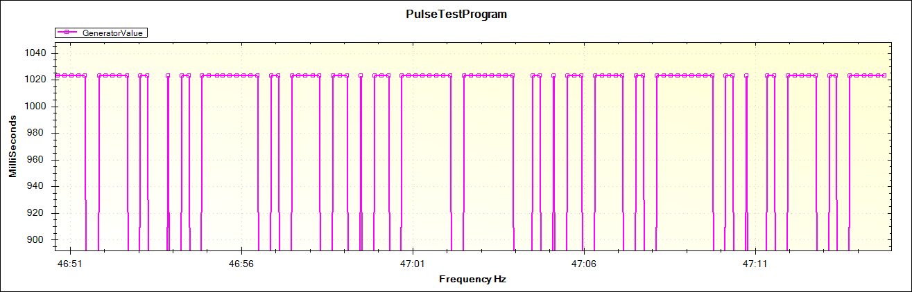
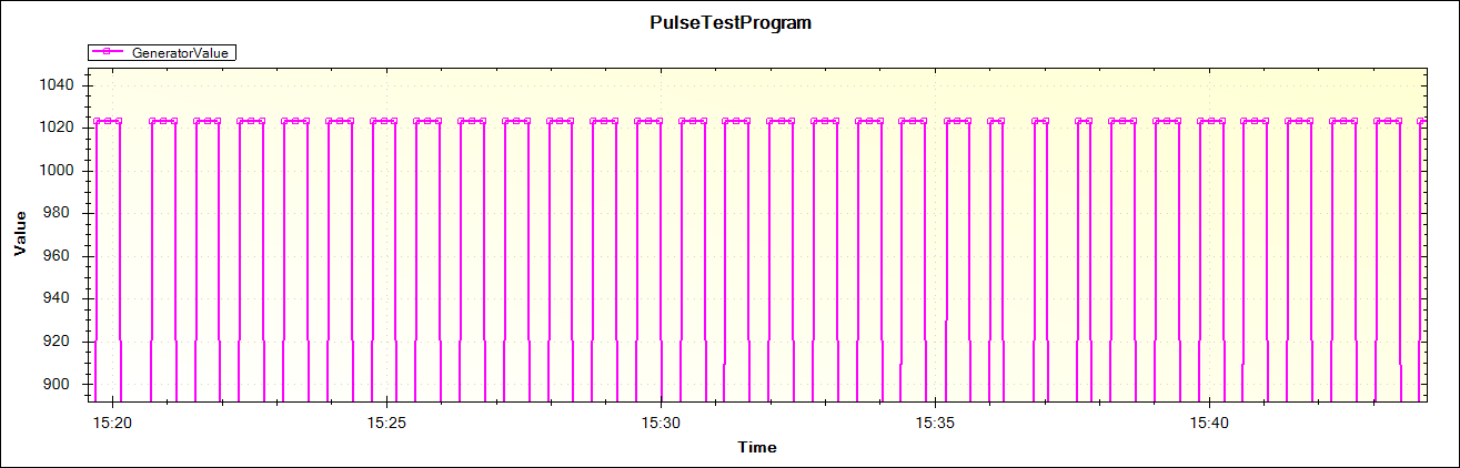
555 Timer Pulse Generator @ Approx 1020 Hz
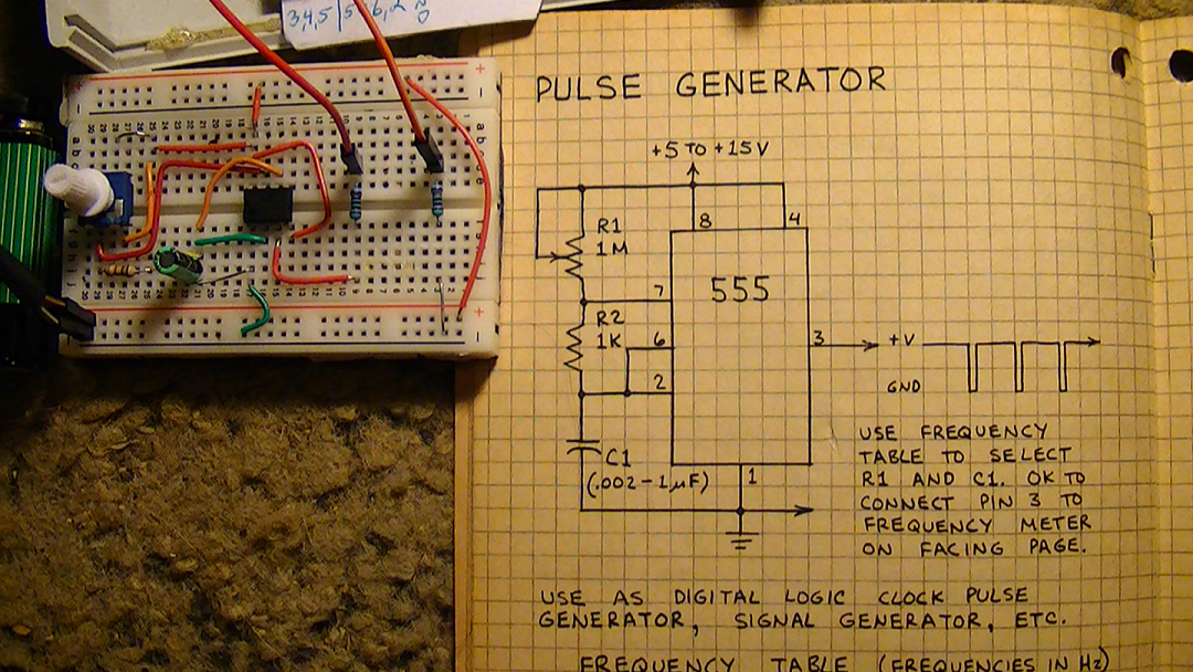
03/29/2017 at 13:16 • 0 commentsI put together a simple pulse generator, using a 555 timer chip from a schematic from an old Forest Mims notebook of mine, so I could calibrate the MCU and MegunoLink Pro to work together when I get ready to link the CCD to the ATmega1284.
These are the results below and they are beautiful :)
Final Plot, 4.47vdc @ 0.26mA
![]()
Code used for this test;
#include "MegunoLink.h" // Helpful functions for communicating with MegunoLink.
// Millis value when the data was last sent.
long LastSent;
// Interval (milliseconds) between sending analog data
const unsigned SendInterval = 200; // [ms]
// The plot we are sending data to.
TimePlot MyPlot;
void setup()
{
Serial.begin(115200);
LastSent = millis();
MyPlot.SetTitle("PulseTestProgram");
MyPlot.SetXlabel("Frequency Hz");
MyPlot.SetYlabel("MilliSeconds");
MyPlot.SetSeriesProperties("GeneratorValue", Plot::Magenta, Plot::Solid, 2, Plot::Square);
}
void loop()
{
if ((millis() - LastSent) > SendInterval)
{
LastSent = millis();
int DataValue = analogRead(PA0);
MyPlot.SendData("GeneratorValue", DataValue);
}
}
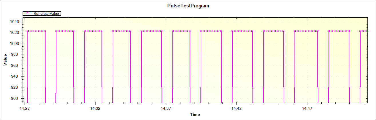
This plot is using a 10k Pot @ 4.53vdc
![]()
![]()
Pulse at 4.98vdc
![]()
Pulse at 4.13vdc
![]()
Pulse at 4.27vdc
![]()
![]()
![]()
-
XR2206 Function Generator/Experiment for setting up serial plotter for TCD1304 CCD Graphing Plot
03/25/2017 at 14:05 • 0 comments*UPDATE* 3/26/2017 9:03:AM
I scrapped my plans for using SerialPortPlotter because writing the routine just was not working out right, between the code for the CCD detector and the serial port, so I searched for a few hours and found the perfect match up, MegunoLink Pro, http://www.megunolink.com/ it has the capability of allowing me to customize my serial interface and the CCD control program in a seamless manner.
I downloaded the free trial and tested it out and immediately it connected and I was monitoring data output, very cool :) It also allows me to log data to a file automatically.
The biggest advantage of this new program will be the ability to write a control program for live capture and calibration of the spectral data in real time and shoot it off in csv file format without having to swim the English channel to get their.
I have a program called "serialportplotter," which is really nice, and has a routine I can modify for using it as the main plotter for downloading the data from the CCD detector. I need it because it is easy to convert the data to csv file format, I know Arduino serial plotter can do this also, but it can only trace 500 data points and I have to copy and paste the data, I no likey that!
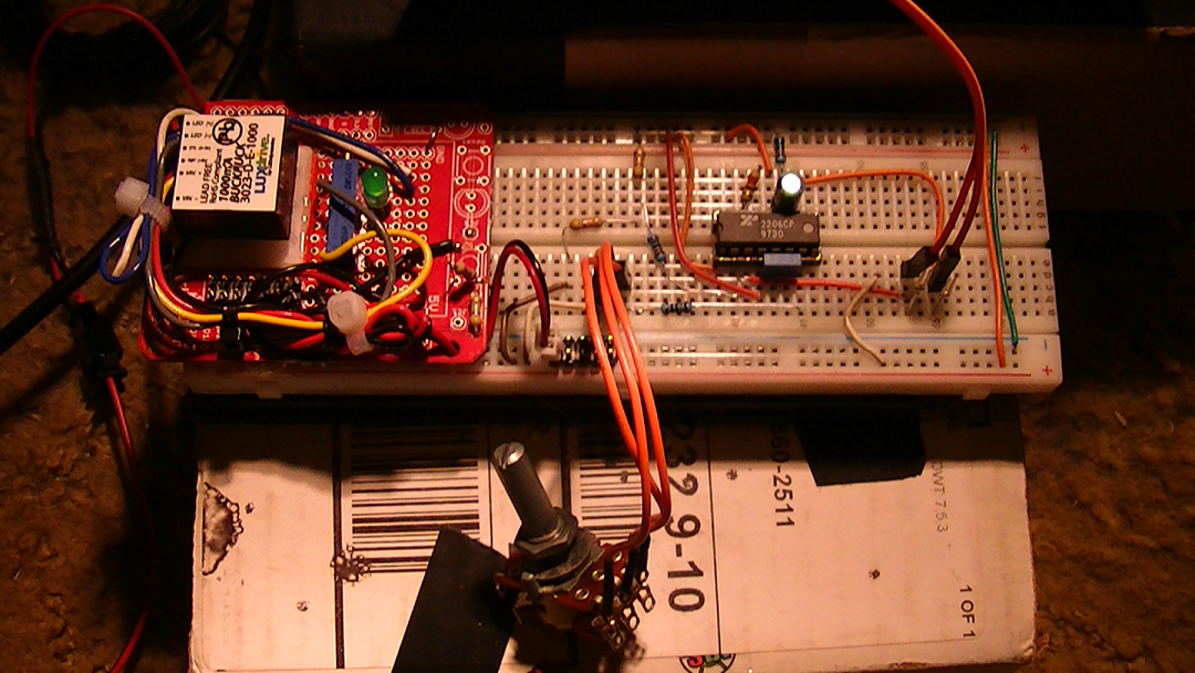
So I put together a quick function generator from an old XR2206 chip I had, with a 12vdc pwr supply, so I could at least display a couple of waveforms easily and test my modified routines out in C, for SerialPortPlotter.
I included a short little video showing a simple square wave from Arduino's serial plotter to make sure that I put the circuit together right, and walla, I did!
http://photos.google.com/photo/AF1QipOj-owuNBgY702v2rmQV8QoVBTvQ_Z94UwIPND0Well, this is it;
![]()
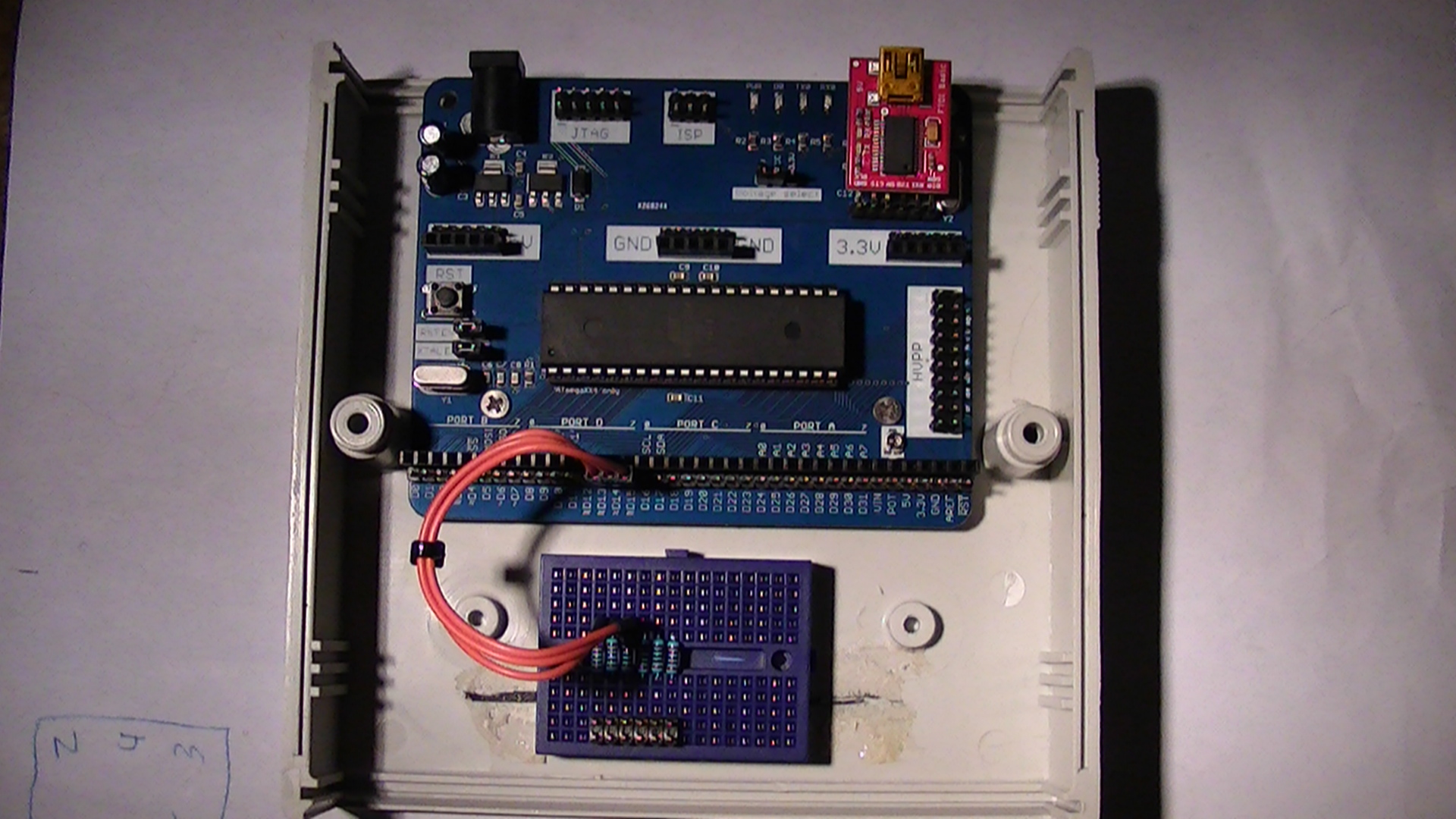
This is the ATmega1284P development board form MCUdude that I bought from the Tindie store;
![]()
-
REV C / TCD1304AP - CCD Detector Module (DAV5 V3 Raman Spectrometer)
03/22/2017 at 08:57 • 0 comments*UPDATE* 3/23/2017 4:59:AM
Ok, I tried to outsmart the AD7667, the LM318p is NOT going to work for the simple reason that the slew rate is too small (50 V/um) even with REV C, the slew rate is still only 70 V/um. The AD8021 has a slew rate of 120 V/um, upon testing the CCD output using the serial plotter, the signal was very "jumpy." (also the LM318's bandwidth is too small, 15MHz.)
Also the MAX232 was getting very hot and I can't afford the ADC getting damaged, so back to placing the AD8021 in it's rightful place. I will have to re-design component placements and get everything to fit on a 99 X 53.2 mm board.
I had to make a major modification to the CCD detector module this week, the leads were too long coming from the ADC to the MCU, so I had to completely de-solder the boards and reconfigure them on one board.
A double sided type configuration, very tedious, but worth it. I got everything on both sides and replaced the AD8021 op amp with the LM318P REV B op amp, reason for this is the ad8021 is so very small and hard to work with, so I sacrificed some speed and bandwidth on the video side of things and the LM318 will provide the same function and low noise, with greater stability for the MAX232.
I sacrificed a little bandwidth at the pre-amp side for the ADC, by placing a 10pf cap at pin 5 of the op amp (the data sheet calls for a 7pf, but I need a little more stability,) so I cut the bandwidth down a bit but increase over all stability of the video output, and the MAX232 can handle the load, and I can still operate at 5vdc.
This is the back end view showing the ADC and MAX232.
![]()
A close up shot of the AD7667 (ADC)
![]()
Below is the TCD1304AP CCD chip module and LM318P op amp
![]()
-
Module 1/TCD1304AP Complete/Module 2/AD7667 Complete
03/12/2017 at 21:34 • 0 commentsWell exactly 98 man hours later, (avg. 14hrs per day*7,) and These are the 2 primary modules and I included the CLI (communication link interface) I had to make this so I could connect the CCD module with the ADC module.
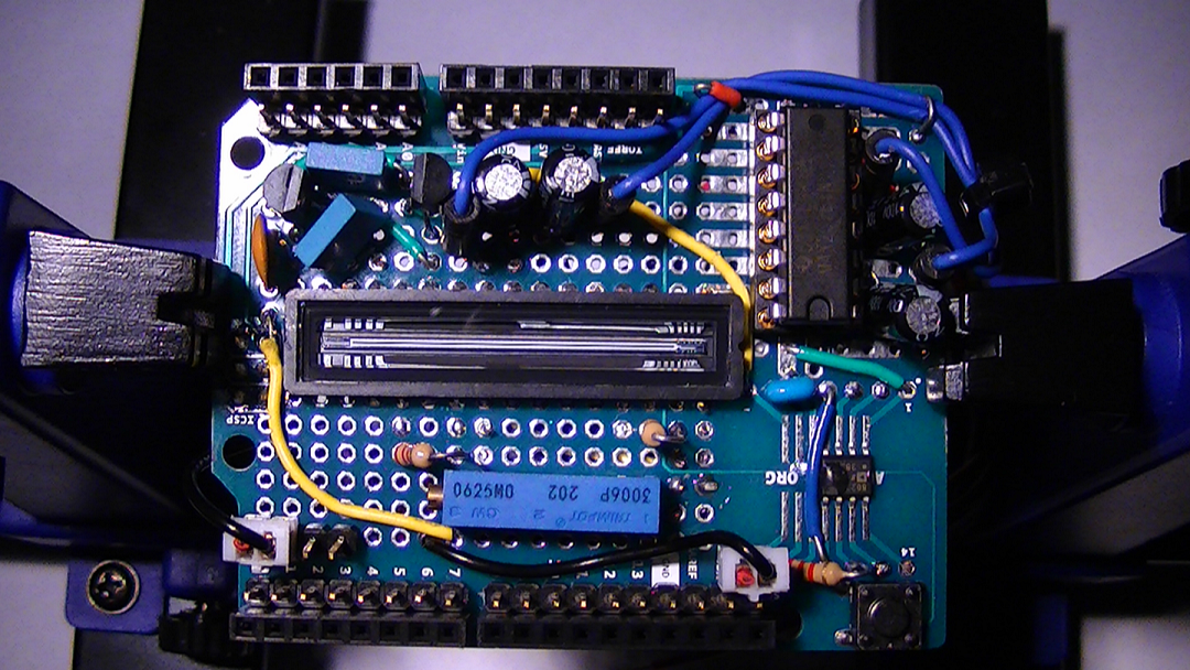
This is the CCD module (1)
![]()
This is the ADC, module (2) Top view
![]()
Below is the bottom view
![]()
This is the CLI, Top view (which will be connected to the inside front face of spectrometer
![]()
Below is the backside view of CLI, CCD module (1) connects to terminal on the left and above view, the 2 x 6 dual terminal with the power indicator LED, faces toward user for connection to MCU and ADC module.
![]()
This is the top cover of the MCU chassis, the trigger switch is already in place with the science frame indicator LED visable
![]()
Close up view of the trigger switch circuit
![]()
Below is the backside view of the switch already mounted in place
![]()
In case you were wondering why there is a 14 pin DIP socket securing the switch? Well, this is a little blast from my past, it was suppose to be a project for a function generator and evidently I never finished it, so I decided to put it to good use anyway :)
-
*UPDATE* Change made To The MCU/ATmega1284 REV B
03/10/2017 at 09:33 • 0 commentsI removed the 1st breadboard strip I had in place as my terminal junction, and used this configuration instead. This makes more sense and gives me room to employ the necessary 100 ohm resistors and other terminals.
![]()
![]()
-
Work Started On The TCD1304 Proto-board/ADC (AD7667) Proto-board
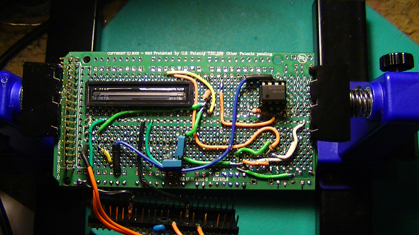
03/10/2017 at 00:37 • 0 commentsThese are the major components soldered in place on the TCD1304AP proto board. This is the 1st board facing the 2nd focal mirror.
![]()
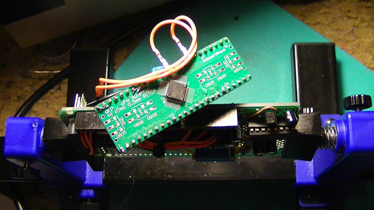
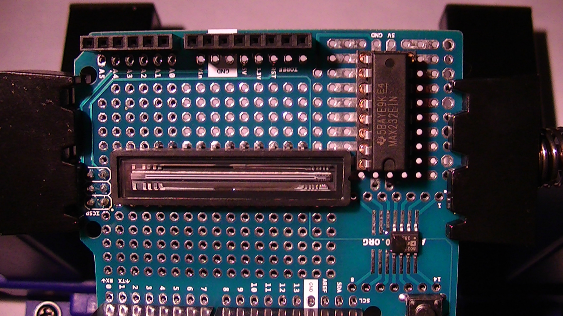
This is a closeup view showing the MAX232EIN and the placement of the AD8021A op-amp.
![]()
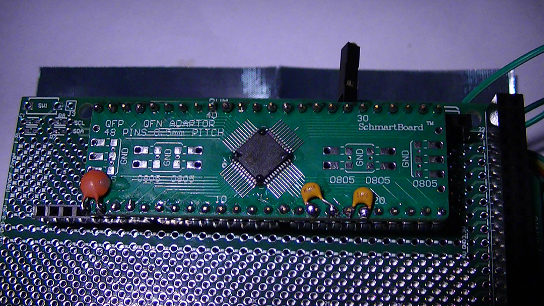
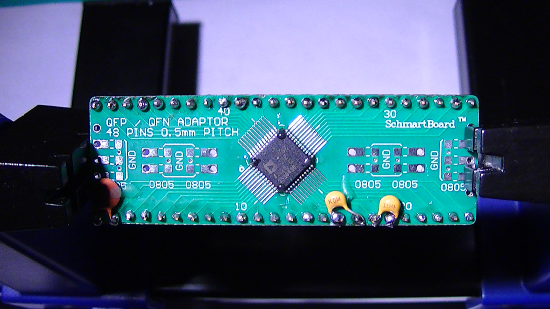
This is the ADC (AD7667AP) placed on a 48 pin Schmartboard. This will be positioned on a 2nd proto board behind the 1st board with a 6 pin dual row terminal for the TCD1304 which will interface separately on the MCU and the rest of the terminating pins on the ADC will have their separate terminal at the MCU.
![]()
DAV5 V3.01 Raman Spectrometer
The only thing worth doing, is the thing worth doing right!


 Here you see how I have the switch and indicator LED set up at the MCU, the LED is normally off, and will light up as soon as data fills the buffer (first science frame,) depress the switch and data is sent, the next science frame gets loaded into the buffer, and so forth...
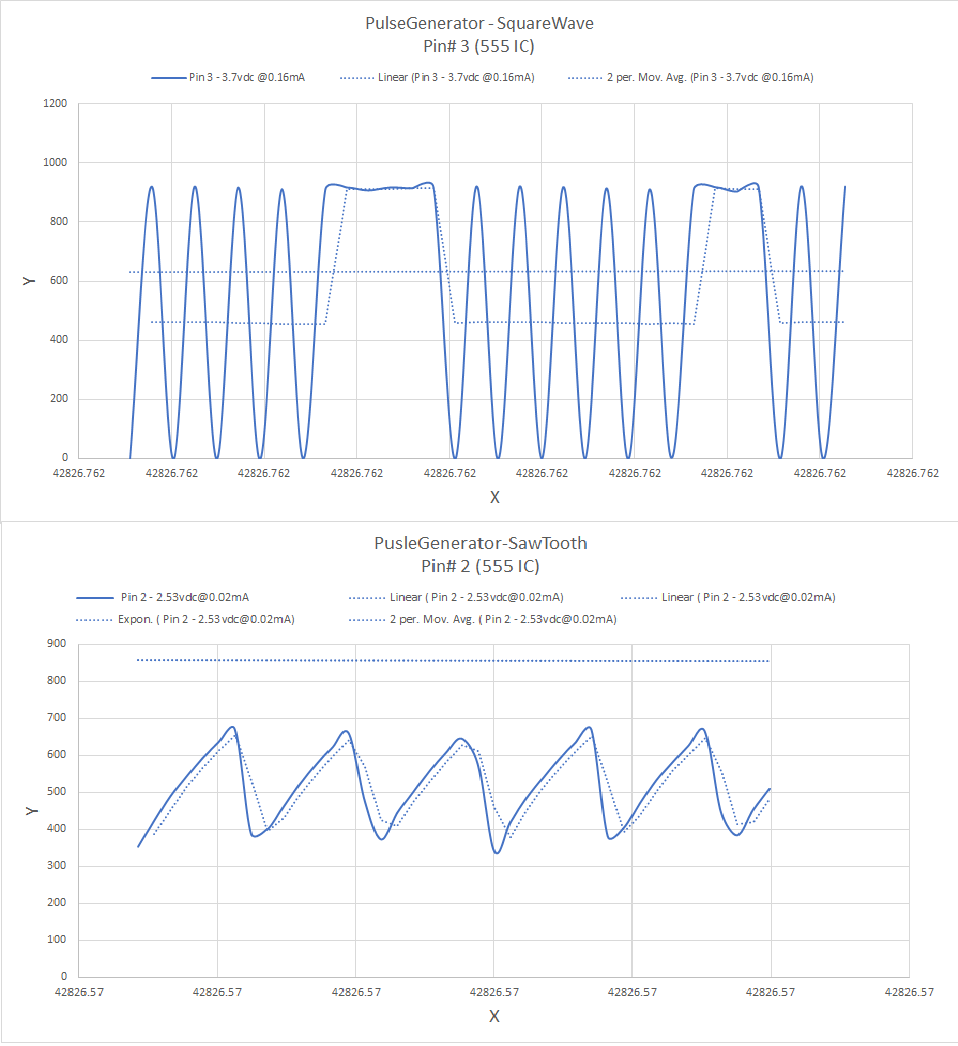 These are the other waveforms I have fiddled with from my test circuit and they work pretty good, I don't have an oscilloscope