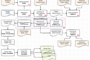
This project is a logical (hmmm) consequence of Tim's project #VHDL/Verilog to Discrete Logic Flow as discussed in the comments of the #TTLers project page.
The whole point of this project is to reduce the cost and pain of soldering hundreds, thousands of identical parts, either through-hole or SMD, when building a reasonably elaborate project. When you reach the scale of a small processor, such as Tim's MCPU seen below, automated pick-and-place and batch soldering are not an option anymore.
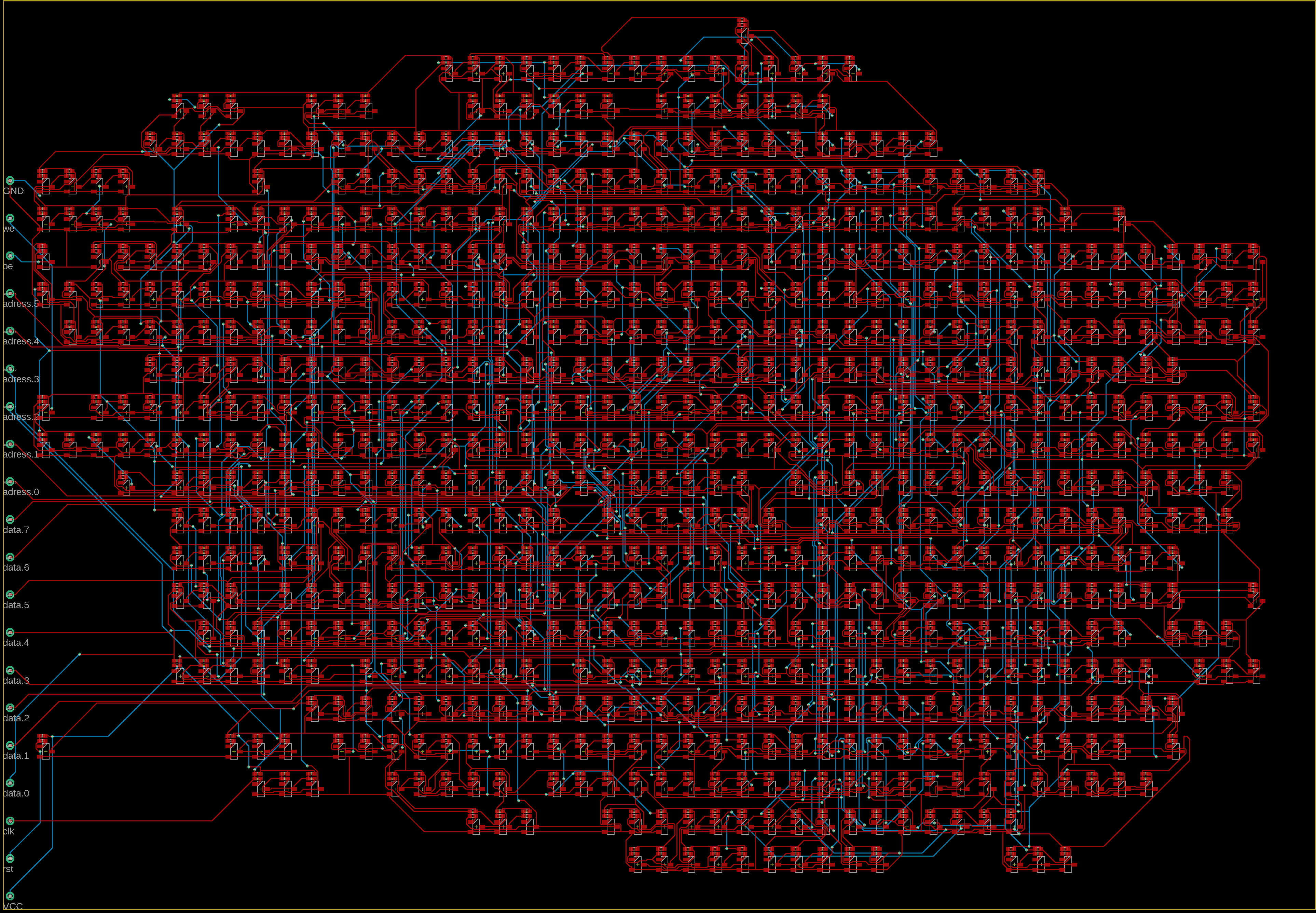
Now, automation is Tim's central idea. But wait, don't we have integrated circuits these days ? Of course we do but they come in fixed sizes, traditionally in DIP packages.
Creating and producing cheap strips of logic gates makes it more convenient and cost-effective for prototypes for example. Identical gates can be cheaply built by machines and then cut-to-measure when and where needed. The designer can then focus more closely on the main board and its routing, as only the connections with the strips need to be soldered (like traditional DIP TTL chips).
But the strips can implement whatever logic family one desires, thus separating architecture from low-level technology. Or so I hope because each family has their own "best flavour" (mostly NOR).
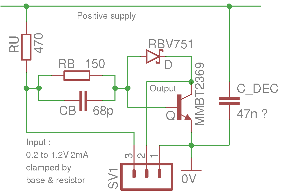
Now I hear you thinking: "yg has another brainfart and nothing tangible to show", as it happens so often. So I already took a few hours (I didn't time it) to make a first "early rendering" based on the gate I already tested for 2ns propagation delay. First let's look at the updated schematic:
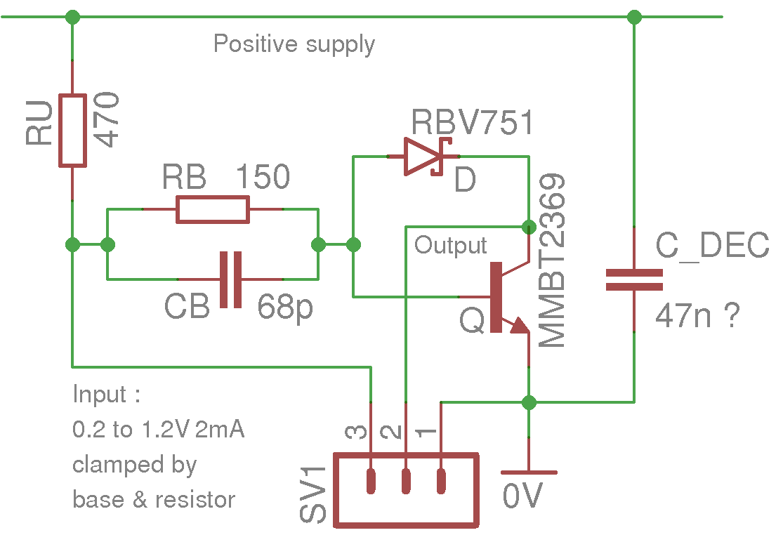
I have followed Tim's method of putting one identical pull-up resistor at the input of the inverter, instead of the output, where the fanout rules dictate an adapted resistor value for each gate. Otherwise it's pretty much what I had tested in the RO9 circuit.
There is only one input because the gates work in "open collector" unlike more modern gates (after all it's 1966 technology, what did you expect?)
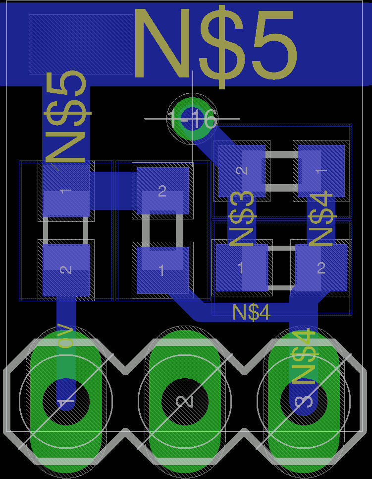
Using SMD parts only, the gate can be quite compact.
- A full reel of MMBT2369 will cost you about 150$ these days, or around $0.05 per part. How far have we gone in 50 years !
- The resistors and capacitors are 0603, nothing special about it. I could have gone to 0201 because I have the option in EAGLE but it will depend on the factory's stocks.
- The diode is a Schottky type in SOD323, rated at < 2pF. The RBV751 is NRND but you could find appropriate equivalent parts.
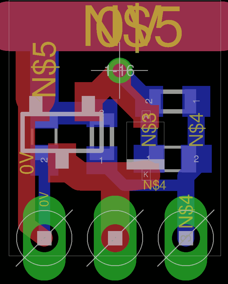
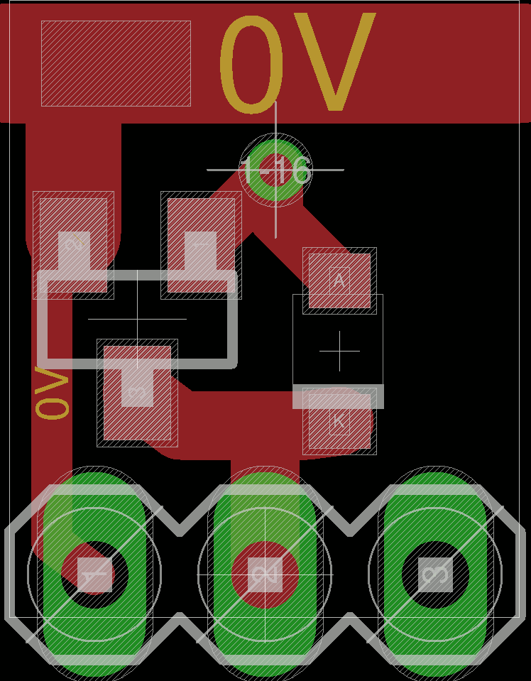
Routing it all on dual-sided PCB was not difficult. It's a first try so don't take it too seriously but it's an interesting approximate.
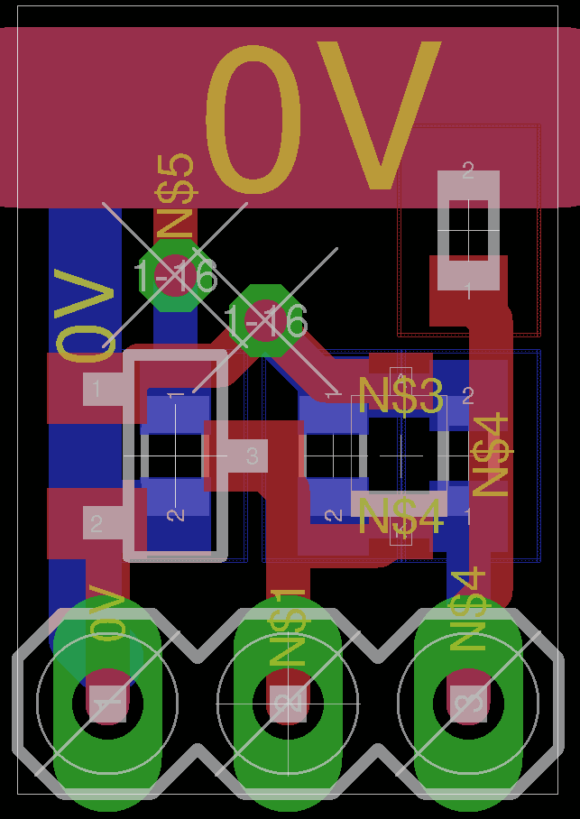
One side has only passives, the other has the actives. Cheap factories might not provide dual-sided oven soldering so the probable method is to ask to solder only the cheap tiny passives, since the transistors and diodes might come from personal stock and sending it to China might be cumbersome.
One side provides the positive supply rail, the other has a reference/ground. A ground pin increase signal integrity for the nets that are perpendicular to the strip direction.
It could be more compact but it's only a first try...
In the above case, about 8 lines of 13 "gates" fit in 100mm×100mm, or 104 gates on the standard DirtyPCB offer. That would bring you about 1040 bare PCB gates for about 17USD.

Concerning the solder : the PCB could be milled to cut the pads in the middle to allow direct soldering, without connector or pin or...
Apart from perpendicular grounding nets, the "motherboard" mainly deals with signal distribution so the router has an easier task. The strips provide ample current and decoupling, which relieves the motherboard.
Now, we need "strips" with different technologies : NMOS, Light Logic, CMOS, I²L, LTL, ECL, TTL, germanium, ...
 Yann Guidon / YGDES
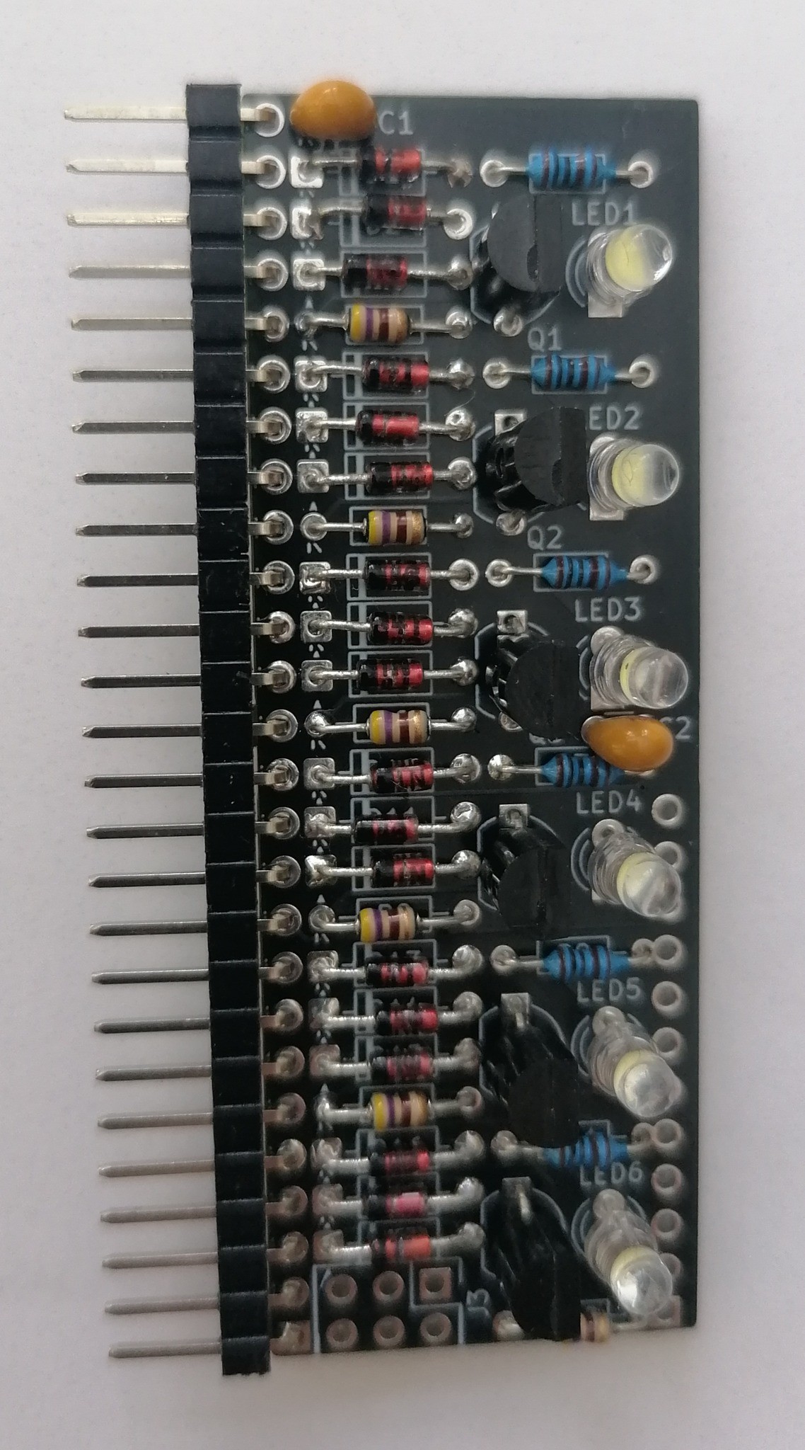


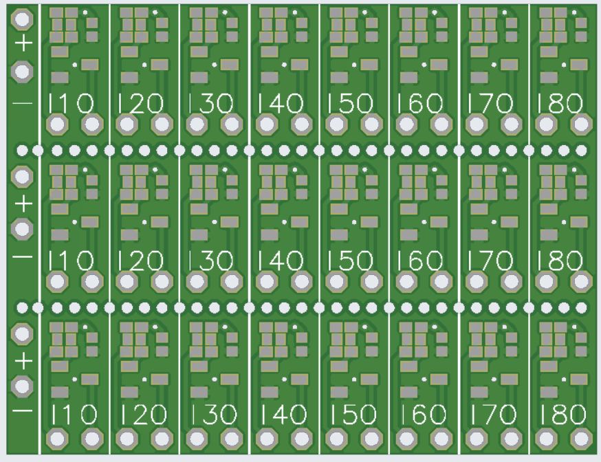
 EDIT2: A version with drill-lines for easy separation


 Tim
Tim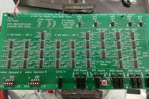
 LorneChrones (Nick)
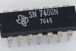
Yann - in your description, you mentioned Little Gates. Is this the same as the TinyLogic series by Fairchild, OnSemi etc?
I checked the cost of the dual inverter NL27WZ04 and it is $0.026 in volume. Whilst slightly more expensive than a transistor, when you consider it's two full inverters or NAND gates you make a saving in passive components.
I know it's cheating, but if you want an inverter with a 2nS propagation delay, in an easy to route 6-pin package, then this might be a starting point.
They will run at 1.65V to 5V and will tolerate up to 5.5V on the inputs.
They can sink/source at least 24mA
They have well defined switching thresholds and could be incorporated into a kind of hybrid "DTL" with double diodes used to provide the inputs.
Tim's workflow / toolchain could be used to generate the board layout.
If I were to create a SMT machine for compactness, where I wanted performance and reliability, I would consider using these dual inverters as a starting point.
https://www.mouser.co.uk/datasheet/2/308/NL27WZ04_D-1813313.pdf