Pavel
Pavel-
Miscellaneous instructions
10/28/2022 at 08:24 • 0 commentsThese are instructions that are more of service nature rather than close related to computation, and couldn't be classified together with them.
All of these instructions take one word in memory.
              Instruction bits
Mnemonic:     F E D C  B A 9 8  7 6 5 4  3 2 1 0
SETIM #M      0 0 0 0  0 1 1 1  m m m x  x x x x    Set interrupt mask #M
CLRIM #M      0 0 0 0  0 1 1 0  m m m x  x x x x    Clear interrupt mask #M
SETPR #P      0 0 0 0  0 1 0 1  p p p x  x x x x    Set prefix #
EINT #I       0 0 0 0  0 1 0 0  i i i i  i i i i    Enter interrupt #I
DMA           0 0 0 0  0 0 1 1  x x x x  x x x x    Direct memory access
RESET         0 0 0 0  0 0 1 0  x x x x  x x x x    software cpu reset
HLT           0 0 0 0  0 0 0 1  x x x x  x x x x    halt execution
NOP           0 0 0 0  0 0 0 0  x x x x  x x x x    empty operation

m - bits of interrupt mask number
p - bits of prefix number
i - bits of interrupt number
x - "don't care" bits - have no effect on result
M - number in range 0-7, each defining particular interrupt mask
P - number in range 0-7
I - number in range 0-255, defining entry into particular interrupt service routine
SETPR - sets prefix that lets to Load, Store or Move 2, 4, 8 or 16 consecutive words and Load or Store 1, 2, 4 or 8 consecutive bytes by corresponding instruction. The actual use in assembly language is by alias B1, B2, B4, B8, W2, W4, W8 or W16 that is written right before the applicable instruction.
EINT is an instruction that triggers interrupt from within running program - as example, this may help with interacting with operating system services.
DMA - makes it possible to change memory contents from outside of CPU (using DMA controller, or front panel switches, or something else). When DMA is in effect, clock signal is not propagating into CPU, making it stop. For CPU resuming the work, the DMA controller should switch clock propagation on.
RESET - clears all registers and flags in CPU, and performs startup sequence.
HLT - stops clock signal propagation into CPU. This can be restored by physically pressing on dedicated Resume button, or the CPU can be restarted by Reset button. This can be useful for inserting breaks during program debugging.
NOP - advances PC 1 word, and nothing else. May be used as filler or some timing application.
-
Assembler
10/27/2022 at 13:28 • 0 commentsPreviously, when computer model was quite different from what it evolved into today, I wrote an assembler in C++ to be able to write somewhat complex programs (such as simple calculator able to perform additions, subtractions, multiplications and divisions on integers) that could be run on a model in simulator.
Now, I have built the model to a degree, when there are quite a few instructions are supported, but many are probably buggy. For the testing purposes, I need to have a machine code for lot of instructions, and crafting it by hand by perusing instruction descriptions and layouts is fairly time consuming process that is prone to errors (such a chore!). As I am debugging the memory access operations, as they are quite complex, with all the data shuffling between registers, buggy instructions are very much complicating the task.
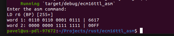
So, to automate the task of converting mnemonics to actual machine instructions, I am started to write a new assembler, from scratch, now in Rust. For now it just reads in a single instruction and outputs the machine code for it. Here is an example of its work:
![]()
This assembler now can encode most of the instructions, exception for the moment are Pointer Arithmetic and Miscellaneous instruction groups.
The immediate plan is to add the instructions from these two last groups -- for now the current functionality might suffice, as the task is debug execution of single instructions.
EDIT (2022-11-06)
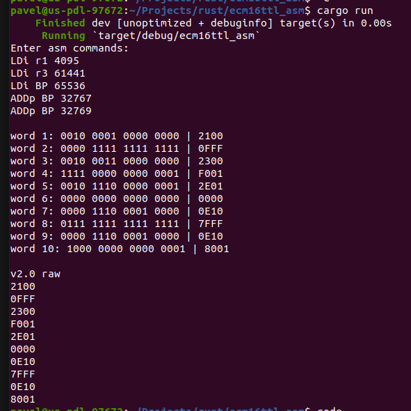
Slightly upgraded the assembler so that now it possible to enter multiple lines (a small program) and assemble them all at once by pressing Enter two times in row.
Now it looks like this:
![]()
The lowermost part of output (starting with "v2.0 raw" line) is formatted so that when saved to file with .hex extension, it can be loaded into ROM component in simulation.
The end goal is to create proper assembly code editor/assembler (windowed application), that will have current mnemonic decoder as its core.
-
Address Arithmetic
10/24/2022 at 07:45 • 0 commentsThere are 3 Address Arithmetic / Pointer Arithmetic instructions that make use of Address Adder to modify values in Memory Pointers, without accessing memory. This is akin to reduced form of Calculating Core operations, where values in General Purpose Registers are modified using Main ALU.
With this group of instructions one can add signed 24-bit value to the value stored in Memory Pointer register pair.
These instructions make use of hardware for indirect memory accesses.
Instruction bits meaning:
bits F, E, D, C, B: opcode for address arithmetic instructions
bits A, 9: Memory Pointer pair index, PC = 00, SP = 01, FP = 10, BP = 11
bit 8: 0 = use 16-bit offset
1 = use 8-bit offset from instruction, in this case bits 7..0 are bits of constant value
bits 7, 6, 5: address of GPR, where offset value is stored
bit 4: 0 = use offset value from GPR
1 = use immediate offset value
bits 3, 2, 1, 0: "don't care"
Instruction layouts:
1) loading / storing at address in MP, without offset:
Instruction words: bits of word #1 bits of word #2 Mnemonic: FEDC BA98 7654 3210 FEDC BA98 7654 3210 ADDp MP rX 0000 1pp0 rrrx xxxx add signed 16-bit value from GPR to MP ADDpi MP 0xFFFF 0000 1pp1 oooo oooo oooo oooo oooo oooo add immediate signed 24-bit value to MP p - bits of Memory Pointer pair index, PC = 00, SP = 01, FP = 10, BP = 11 r - bits of register address (X) where offset value is stored o - bits of immediate offset value x - "don't care" bits - have no effect on result rX - General Purpose Register #X MP - Memory Pointer pair (either of PC, SP, FP and BP) -
Jumps
10/23/2022 at 11:30 • 0 commentsJump instructions implicitly load Program Counter (first Memory Pointer registers pair) which facilitates changes in program execution flow. There are 2 unconditional jumps (J and JSR), and 8 conditional ones that leads to conditional branching of program flow.
All jump addresses are indirect, they are the current value in Program Counter pair with offsets added.
There are 4 flags setting condition for jump: Carry (C), Overflow (O), Negative (N) and Zero (Z). The 8 conditions are for each flag to be equal 0 or 1. The flags are set by the last ALU operation.
Some additional details about Jump and JSR instruction execution are described in this post.
Other instructions can be investigated here: General layout of instruction types.
Instruction bits meaning:
bits F, E, D, C: opcode for jumps
bits B, A, 9, 8: condition
bits 7..0: top 8 bits of 24-bit offset value
Instruction layouts:
             Instruction words:
             bits of word #1      bits of word #2
Mnemonic:    FEDC BA98 7654 3210  FEDC BA98 7654 3210
J offset     0001 0000 oooo oooo  oooo oooo oooo oooo   unconditional jump
JZ offset    0001 0001 oooo oooo  oooo oooo oooo oooo   jump if Zero
JN offset    0001 0010 oooo oooo  oooo oooo oooo oooo   jump if Negative
JO offset    0001 0100 oooo oooo  oooo oooo oooo oooo   jump if Overflow
JC offset    0001 1000 oooo oooo  oooo oooo oooo oooo   jump if Carry
JNZ offset   0001 1110 oooo oooo  oooo oooo oooo oooo   jump if NOT Zero
JNN offset   0001 1101 oooo oooo  oooo oooo oooo oooo   jump if NOT Negative
JNO offset   0001 1011 oooo oooo  oooo oooo oooo oooo   jump if NOT Overflow
JNC offset   0001 0111 oooo oooo  oooo oooo oooo oooo   jump if NOT Carry
JSR offset   0001 1111 oooo oooo  oooo oooo oooo oooo   jump to Subroutine

o - bits of immediate offset value
All Jumps are PC relative, which makes code position-independent.
The jumps are restricted to no further than +-8388607 bytes from current value of PC.
In the Jump instructions, two words are loaded into PC register pair to yield a new 32-bit address.
Some circuitry is shared between jumps and Address Arithmetic operations on hardware level.
In case the condition is not met, PC is not loaded with new value, and execution proceeds to the next instruction in the program.
Jump to Subroutine:
This is a special type of jump, where PC is stored to memory right before the jump.
1st, store contents of PC to location pointed to by SP,
2nd, update PC with PC + offset value.
-
Indirect memory accesses
10/23/2022 at 10:14 • 0 commentsLoading and Storing of data at addresses calculated at runtime from values stored in registers and/or immediate values in instructions.
There are 8 ways to calculate these addresses, for each there is a Load and Store instruction, in all there are 16 instructions in this group.
There is always a Memory Pointer register pair used for providing base address, this can be one of: Program Counter (PC), Stack Pointer (SP), Frame Pointer (FP) and Base Pointer (BP).
Load or Store can be performed to and from any of the General Purpose Registers(GPR) and any of Memory Pointer Registers(MP).
For calculating addresses, signed 16-bit offset can be used, it is provided either from one of GPR, or from immediate value.
When multi-word flag is set, several consecutive registers can have their contents stored to memory or several words from memory can be loaded into corresponding number of consecutive registers with one instruction. In this case, there are additional clock cycles spent for each additional word. As Load/Store operations themselves take up several clock cycles, loading/storing 2 and more registers using one instruction will save clock cycles compared to loading/storing each word individually.
Other instructions can be investigated here: General layout of instruction types.
Instruction bits meaning:bits F, E, D: opcode for indirect memory access
bit C: 0 = load, 1 = store
bit B: 0 = GPR, 1 = MP
bits A, 9, 8: register address for load/store
bits 7, 6, 5: address of register containing offset value
bit 4: 0 = do NOT update MP at memory access,
1 = update MP at memory access (either post- or pre- increment, depending on bit 3)
bit 3: 0 = do NOT add offset before accessing the memory (post-increment if bit 4 = 1),
1 = add offset before accessing the memory (pre-increment if bit 4 = 1),
bit 2: 0 = use offset from GPR, 1 = use immediate value for offset
bits 1, 0: Memory Pointer pair index
Instruction layouts:1) LD and ST: loading / storing at address in MP, without offset:
               Instruction words:
               bits of word #1      bits of word #2
Mnemonic:      FEDC BA98 7654 3210  FEDC BA98 7654 3210
LD rX MP       0110 dddd xxx0 00aa
ST rX MP       0111 ssss xxx0 00aa
LD rX MP*      0110 dddd xxx0 01aa  xxxx xxxx xxxx xxxx
ST rX MP*      0111 ssss xxx0 01aa  xxxx xxxx xxxx xxxx

d, s - bits of register address (X or MP) which is destination or source
a - bits of Memory Pointer pair index, PC = 00, SP = 01, FP = 10, BP = 11
x - "don't care" bits - have no effect on result
rX - General Purpose Register #X
MP - Memory Pointer pair (either of PC, SP, FP and BP)

* - this pair of instructions is possible, because hardware is capable of executing them.
They have the same effect as the first pair, only take up more space in memory
 and 1 more clock cycle to execute.
These instructions, however, will not be output from assembler - they are superfluous.
2) LDr/LDo and STr/STo: loading / storing at address in MP + offset, MP value stays the sameInstruction words: bits of word #1 bits of word #2 Mnemonic: FEDC BA98 7654 3210 FEDC BA98 7654 3210 LDr rY MP rX 0110 dddd rrr0 10aa STr rY MP rX 0111 ssss rrr0 10aa LDo rY MP 0xFFFF 0110 dddd xxx0 11aa oooo oooo oooo oooo STo rY MP 0xFFFF 0111 ssss xxx0 11aa oooo oooo oooo oooo d, s - bits of register address (Y or MP) which is destination or source a - bits of Memory Pointer pair index, PC = 00, SP = 01, FP = 10, BP = 11 r - bits of register address (X) that holds offset value o - bits of immediate offset value x - "don't care" bits - have no effect on result rX, rY - General Purpose Registers #X and #Y MP - Memory Pointer pair (either of PC, SP, FP and BP) OxFFFF -signed 16-bit offset value (in range -32768..+32767)
3) LDra/LDoa and STra/SToa: loading / storing at address in MP, and after this, update MP value with its current value + offset (loads/stores with POST-increment of MP)Instruction words: bits of word #1 bits of word #2 Mnemonic: FEDC BA98 7654 3210 FEDC BA98 7654 3210 LDra rY MP rX 0110 dddd rrr1 00aa STra rY MP rX 0111 ssss rrr1 00aa LDoa rY MP 0xFFFF 0110 dddd xxx1 01aa oooo oooo oooo oooo SToa rY MP 0xFFFF 0111 ssss xxx1 01aa oooo oooo oooo oooo d, s - bits of register address (Y or MP) which is destination or source a - bits of Memory Pointer pair index, PC = 00, SP = 01, FP = 10, BP = 11 r - bits of register address (X) that holds offset value o - bits of immediate offset value x - "don't care" bits - have no effect on result rX, rY - General Purpose Registers #X and #Y MP - Memory Pointer pair (either of PC, SP, FP and BP) OxFFFF -signed 16-bit offset value (in range -32768..+32767)
4) LDrb/LDob and STrb/STob: update MP value with its current value + offset before loading / storing at updated address (loads/stores with PRE-increment of MP)Instruction words: bits of word #1 bits of word #2 Mnemonic: FEDC BA98 7654 3210 FEDC BA98 7654 3210 LDrb rY MP rX 0110 dddd rrr1 10aa STrb rY MP rX 0111 ssss rrr1 10aa LDob rY MP 0xFFFF 0110 dddd xxx1 11aa oooo oooo oooo oooo STob rY MP 0xFFFF 0111 ssss xxx1 11aa oooo oooo oooo oooo d, s - bits of register address (Y or MP) which is destination or source a - bits of Memory Pointer pair index, PC = 00, SP = 01, FP = 10, BP = 11 r - bits of register address (X) that holds offset value o - bits of immediate offset value x - "don't care" bits - have no effect on result rX, rY - General Purpose Registers #X and #Y MP - Memory Pointer pair (either of PC, SP, FP and BP) OxFFFF -signed 16-bit offset value (in range -32768..+32767) -
Immediate loads
10/23/2022 at 08:43 • 0 commentsLoading hard coded value into one of the registers.
The instruction is 2 words (32bit).
There are 2 types of this instruction - one for loading a word (16bit) into General Purpose Register, and other for loading a double word (32bit value in range 0x00000000 - 0x01ffffff) into a pair of Memory Pointer registers.
Here are layouts:
                     Instruction words:
                     bits of word #1      bits of word #2
Mnemonic:            FEDC BA98 7654 3210  FEDC BA98 7654 3210
LDir rX 0xffff       0010 0ddd xxxx xxxx  vvvv vvvv vvvv vvvv
LDim MP 0x01ffffff   0010 1ddv vvvv vvvv  vvvv vvvv vvvv vvvv

d - bits of register address (X or MP)
v - bits of data value to be loaded
x - "don't care" bits - have no effect on result
rX - General Purpose Register #X
MP - Memory Pointer register pair, one of Program Counter (PC), Stack Pointer (SP),
 Frame Pointer (FP) and Base Pointer (BP)
There are no corresponding Store Immediate instructions, as it is has no practical use -- the write will be into program area at address that cannot be readily predicted and utilized at code writing time.
-
Loading/Storing data at direct address
10/23/2022 at 08:06 • 0 commentsThis instruction provides means to load/store data at address explicitly hard coded into the instruction itself.
The instruction has length of 2 words (32 bit). As addresses themselves are 32-bit, here is a bit of compromise made -- for the loads and stores only 24 bits of address are used, therefore, there is only 16M addresses available in this mode. These are split in two equal ranges - at the top and the bottom of full address space. At the bottom there is supposed to be common RAM, and at the top the I/O should be mapped. So these transfers are primarily for I/O operations.
The transfers are limited to be word-addressable.
Here is instruction layouts:
                     Instruction words:
                     bits of word #1      bits of word #2
Mnemonic:            FEDC BA98 7654 3210  FEDC BA98 7654 3210
LDd rX 0x01ffffff    0100 0ddd aaaa aaaa  aaaa aaaa aaaa aaaa
STd rX 0x01ffffff    0101 0sss aaaa aaaa  aaaa aaaa aaaa aaaa
LDd mpX 0x01ffffff   0100 1ddd aaaa aaaa  aaaa aaaa aaaa aaaa
STd mpX 0x01ffffff   0101 1sss aaaa aaaa  aaaa aaaa aaaa aaaa

d, s - bits of register address (X) of Destination or Source register,
 where data is loaded to from memory or stored from to memory
a - bits of hard coded memory address
rX - general purpose register
mpX - memory pointer register
0x01ffffff - explicit memory address
When writing mnemonic / asm command, the address is written fully (as byte address), but in the resulting instruction the last bit is discarded (and implicitly is set to 0), thus the instruction itself holds the word address.
For addresses in range 0x00000000 - 0x00ffffff, bottom range is targeted, for ones in range 0x01000000 - 0x01ffffff - the top range is targeted. If the address provided is bigger than 0x01ffffff, the assembler should throw error or convert to the top range.
Each range is 8M words, or 16 Mbytes.
-
MOV instructions
10/22/2022 at 20:00 • 0 commentsMOV instructions are copying data between registers in CPU.
All MOV instructions are taking up a single word, and need one clock cycle to fetch and one to execute.
When multi-word flag is set, several consecutive registers can have their contents copied to other group of consecutive registers with one instruction. In this case, there is one clock cycle for fetch, and a number of clock cycles to execute, corresponding to the number of registers moved.
Regular Move (MOV)
There are 2 register files in CPU: General Purpose Registers (GPR) and Memory Pointers (MP), and therefore there are 4 types of register transfers: GPR -> GPR, GPR -> MP, MP -> GPR and MP -> MP.
              Instruction bits
Mnemonic:     F E D C  B A 9 8  7 6 5 4  3 2 1 0
MOV rB rA     0 0 1 1  0 d d d  s s s 0  0 x x x    move GPR to other GPR
MOV mpB mpA   0 0 1 1  1 d d d  s s s 1  0 x x x    move MP to other MP
MOV mpB rA    0 0 1 1  1 d d d  s s s 0  0 x x x    move GPR A to MP B
MOV rB mpA    0 0 1 1  0 d d d  s s s 1  0 x x x    move MP A to GPR B

s - bits of source register address(A), where data is coming from
d - bits of destination register address(B), where data is written to
x - "don't care" bits - have no effect on result
A, B - numbers in range 0-7, they are register addresses
Both GPR and MP are numbered 0 through 7, so there are 2 sets of 8 registers. To disambiguate between them, bits B and 4 are used for destination and source respectively. If disambiguating bit is 0, the GPR is addressed, if it is 1, then it is MemPointer.
Special Move (MOVs)
Bit 3 indicates register transfers to additional registers, such as MDB, IVB, and SR.
Bit 2 indicates transfer direction -- 0 = read special reg, 1 = write special reg.
Bits 0 and 1 are used as address of special registers.
Instruction bits Mnemonic: F E D C B A 9 8 7 6 5 4 3 2 1 0 MOVs rB SR 0 0 1 1 d d d d x x x x 1 0 0 1 move SR to rA MOVs SR rA 0 0 1 1 x x x x s s s s 1 1 0 1 move rA to SR MOVs rB MDB 0 0 1 1 d d d d x x x x 1 0 1 0 move MDB to rA MOVs MDB rA 0 0 1 1 x x x x s s s s 1 1 1 0 move rA to MDB MOVs rB IVB* 0 0 1 1 d d d d x x x x 1 0 1 1 -- cannot read IBV MOVs IVB rA 0 0 1 1 x x x x s s s s 1 1 1 1 move rA to SR s - bits of source register address(A), where data is coming from d - bits of destination register address(B), where data is written to x - "don't care" bits - have no effect on result A, B - numbers in range 0-7, they are register addresses -
ALU instructions
01/28/2022 at 12:04 • 0 commentsALU instructions make use of the main ALU to perform arithmetic and logic operations on data stored in 8 General Purpose Registers.
The results of these operations are stored in One of the GPR and in Status Register (flags indicating some aspects of operation results that can be then used as conditions for branching).
All ALU instructions are taking up a single word, and need one clock cycle to fetch and one to execute. ALU instruction cycles are staggered, the execution of the the ALU instruction is in parallel with the fetching of the next instruction. In case of several ALU instructions in a row, throughput is 1 instruction per clock cycle.
Other instructions can be investigated here: General layout of instruction types.
There are several types of ALU instructions:
1) arithmetic and logical operations between a 16-bit value in register and 8-bit constant hard coded into instruction word (immediate ops):
                Instruction bits
Mnemonic:       F E D C  B A 9 8  7 6 5 4  3 2 1 0
ADDi rA 0xFF    1 0 0 0  1 a a a  c c c c  c c c c
SUBi rA 0xFF    1 0 0 1  1 a a a  c c c c  c c c c
XORi rA 0xFF    1 0 1 0  1 a a a  c c c c  c c c c
XNORi rA 0xFF   1 0 1 1  1 a a a  c c c c  c c c c
ORi rA 0xFF     1 1 0 0  1 a a a  c c c c  c c c c
ORNi rA 0xFF    1 1 0 1  1 a a a  c c c c  c c c c
ANDi rA 0xFF    1 1 1 0  1 a a a  c c c c  c c c c
ANDNi rA 0xFF   1 1 1 1  1 a a a  c c c c  c c c c

a - bits of register address(A) where 16-bit value comes from,
and result is written to
c - bits of hard coded 8-bit constant
A - number in range 0-7, this is register address
0xFF - constant in range 0-255
2) Arithmetic operations between two values from registers, with write to third register: Add, Subtract, Add with Carry and Subtract with Carry:
                Instruction bits
Mnemonic:       F E D C  B A 9 8  7 6 5 4  3 2 1 0
ADD rY rA rB    1 0 0 0  0 y y y  a a a 0  0 b b b
SUB rY rA rB    1 0 0 1  0 y y y  a a a 0  0 b b b
ADDC rY rA rB   1 0 0 0  0 y y y  a a a 0  1 b b b
SUBC rY rA rB   1 0 0 1  0 y y y  a a a 0  1 b b b

a - bits of register address A of the first operand
b - bits of register address B of the second operand
y - bits of register address Y for result to be written to
A, B, Y - numbers in range 0-7, they are register addresses
3) Logic operations between two values from registers, with write to third register
                Instruction bits
Mnemonic:       F E D C  B A 9 8  7 6 5 4  3 2 1 0
XOR rY rA rB    1 0 1 0  0 y y y  a a a 0  0 b b b
XNOR rY rA rB   1 0 1 1  0 y y y  a a a 0  0 b b b
OR rY rA rB     1 1 0 0  0 y y y  a a a 0  0 b b b
ORN rY rA rB    1 1 0 1  0 y y y  a a a 0  0 b b b
AND rY rA rB    1 1 1 0  0 y y y  a a a 0  0 b b b
ANDN rY rA rB   1 1 1 1  0 y y y  a a a 0  0 b b b

a - bits of register address A of the first operand
b - bits of register address B of the second operand
y - bits of register address Y for result to be written to
A, B, Y - numbers in range 0-7, they are register addresses
4) Two-operand operations without writing the result (operations CMN, TST and TEQ are taken from ARM ISA described on this page):
Zero flag is set when result is True, except for TST where Zero flag is cleared for True.
                Instruction bits
Mnemonic:       F E D C  B A 9 8  7 6 5 4  3 2 1 0
TEQ rA rB       1 0 1 0  0 x x x  a a a 0  1 b b b    Test equivalence (rA XOR rB)
TCM rA rB       1 0 1 1  0 x x x  a a a 0  1 b b b    Test complement (rA XNOR rB)
CMN rA rB       1 1 0 0  0 x x x  a a a 0  1 b b b    Compare Negative (rA + rB)
CMP rA rB       1 1 0 1  0 x x x  a a a 0  1 b b b    Compare (rA - rB)
TST rA rB       1 1 1 0  0 x x x  a a a 0  1 b b b    Test bits (rA AND rB)
TIB rA rB       1 1 1 1  0 x x x  a a a 0  1 b b b    Test inverted bits (rA ANDN rB)


a - bits of register address A of the first operand
b - bits of register address B of the second operand
x - "don't care" bits - have no effect on result
A, B - numbers in range 0-7, they are register addresses
5) 1-bit shift operations:
              Instruction bits
Mnemonic:     F E D C  B A 9 8  7 6 5 4  3 2 1 0
SHL rB rA     1 0 1 0  0 d d d  s s s 1  0 0 x x    shift 1 bit left
SHR rB rA     1 0 1 1  0 d d d  s s s 1  0 0 x x    shift 1 bit right
ROLC rB rA    1 0 1 0  0 d d d  s s s 1  1 0 x x    rotate through carry 1 bit left
RORC rB rA    1 0 1 1  0 d d d  s s s 1  1 0 x x    rotate through carry 1 bit right
ASHL rB rA    1 0 1 0  0 d d d  s s s 1  x 1 x x    arithm shift left, same as regular shift
ASHR rB rA    1 0 1 1  0 d d d  s s s 1  x 1 x x    arithmetic shift right,
                                                    when msb is copied to the right

s - bits of source register address A, where value is coming from
d - bits of destination register address B, where result is written to
x - "don't care" bits - have no effect on result
A, B - numbers in range 0-7, they are register addresses
6) Multi-bit rotations -- the set number of most significant bits get moved to be least significant bits in word:
                Instruction bits
Mnemonic:       F E D C  B A 9 8  7 6 5 4  3 2 1 0
ROTi rY rA 0xF  1 1 0 1  0 d d d  s s s 1  n n n n    Rotate 0xF (0-16) bits left
ROT rY rA rB    1 1 0 0  0 d d d  s s s 1  x r r r    Rotate (value in reg rB) bits left

s - bits of source register address A, where value is coming from
d - bits of destination register address Y, where result is written to
n - bits of the rotation number 0xF
r - bits of register address B where rotation number is coming from
x - "don't care" bits - have no effect on result
A, B, Y - numbers in range 0-7, they are register addresses
When rotating by value from register rB, the 4 least significant
 bits of rotation value are used.
7) Byte sign extend - copy bit 7 into bits 8 through F:
                Instruction bits
Mnemonic:       F E D C  B A 9 8  7 6 5 4  3 2 1 0
BSE rB rA       1 0 0 x  0 d d d  s s s 1  x x x x

s - bits of source register address A, where value is coming from
d - bits of destination register address B, where result is written to
x - "don't care" bits - have no effect on result
8) Invert - change all 0s to 1s and all 1s to 0s:
                Instruction bits
Mnemonic:       F E D C  B A 9 8  7 6 5 4  3 2 1 0
INV rB rA       1 1 1 x  0 d d d  s s s 1  x x x x

s - bits of source register address A, where value is coming from
d - bits of destination register address B, where result is written to
x - "don't care" bits - have no effect on result
-
General bit layout for instruction types
01/26/2022 at 10:36 • 0 commentsAll instructions are 16-bit wide (1 word), with optional extension of 16 more bits for immediate value needed for some of these instructions.
Bit patterns for the instruction types:

bits in instruction word:   FEDC BA98 7654 3210  [extension]
ALU:                        1xxx xxxx xxxx xxxx
Load/Store via Mem Pointer: 011x xxxx xxxx xxxx  xxxx xxxx xxxx xxxx
Load/Store via direct addr: 010x xxxx xxxx xxxx  xxxx xxxx xxxx xxxx
MOV:                        0011 xxxx xxxx xxxx
Load immediate value:       0010 xxxx xxxx xxxx  xxxx xxxx xxxx xxxx
Jumps:                      0001 xxxx xxxx xxxx  xxxx xxxx xxxx xxxx
Address Arithmetic:         0000 1xxx xxxx xxxx  xxxx xxxx xxxx xxxx
Miscellaneous ops:          0000 0xxx xxxx xxxx
All the 'x' places above can be either 0 or 1, depending on particular instruction.
The extension word with immediate value is always present for Loads/Stores via direct address, Loads of immediate values and Jumps, while for the Loads/Stores via Memory Pointer + offset and Address Arithmetic instruction types it is optional, and depends on particular instruction. Thus, although I tried to make the ISA RISC-like, it has some elements of CISC in a sense that not all instructions are the same size.
Instruction Set for ECM-16/TTL homebrew cpu
All the instructions laid out in systematic manner