-
[M][T] Flat flexible cable
08/01/2024 at 11:25 • 0 commentsSo I've recently designed the new PCB for Tetoroidiv and now I've tried adding an 80mm FFC to it.
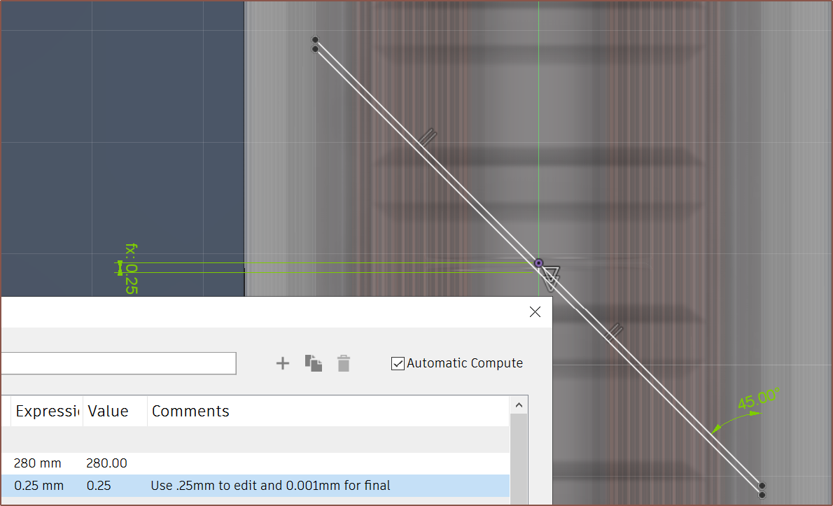
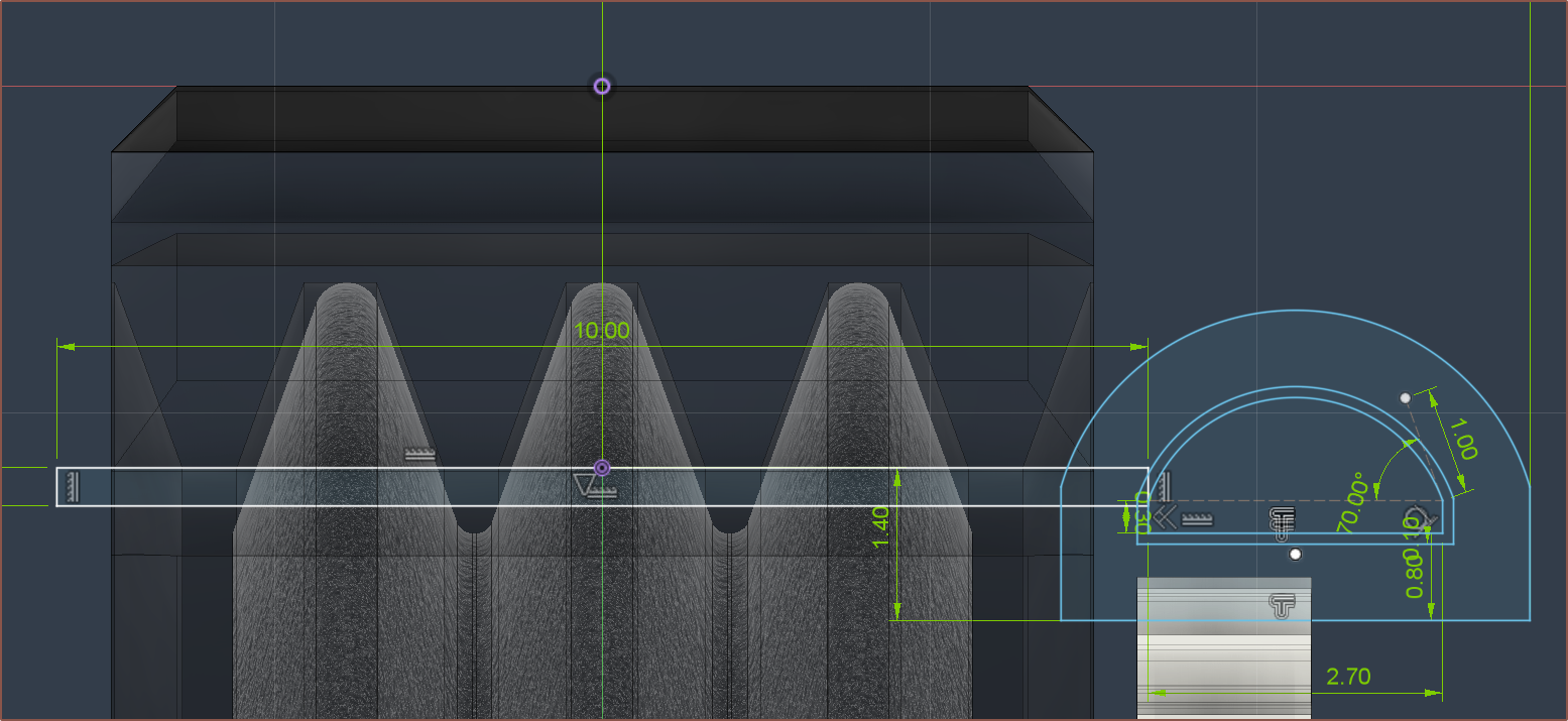
The annoying thing about Fusion is that it will preview a 180 degree bend but will not actually allow the OK button to be pressed, so I had to work around it:
Then I click the bottom line with setting "Start" and the top line with setting "End".
Since there's space, I'm considering actually just soldering all the wires from Tetrinsic to the Tetoroidiv PCB and then potting the entire thing to achieve water protection. The less separate things I need to waterproof, the better, and if I use silicone, it seems (from the video below, timestamp 4:33) that it should be easily removable if needed:
-
[E4][M] Geartrain
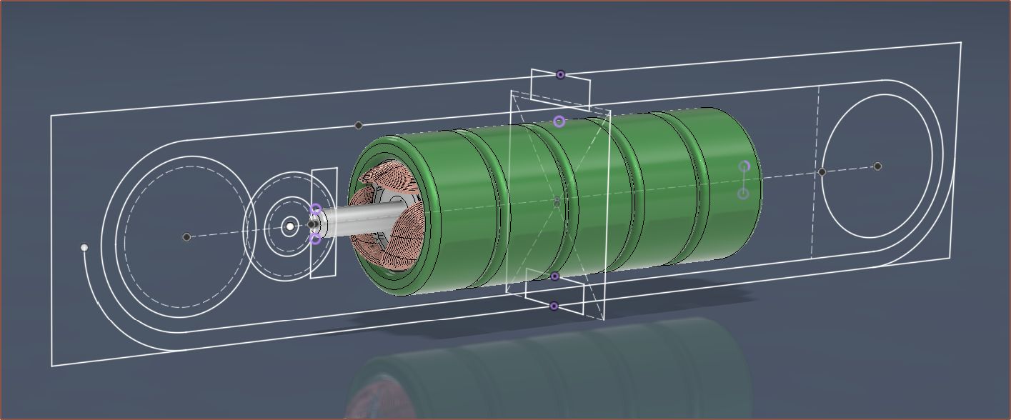
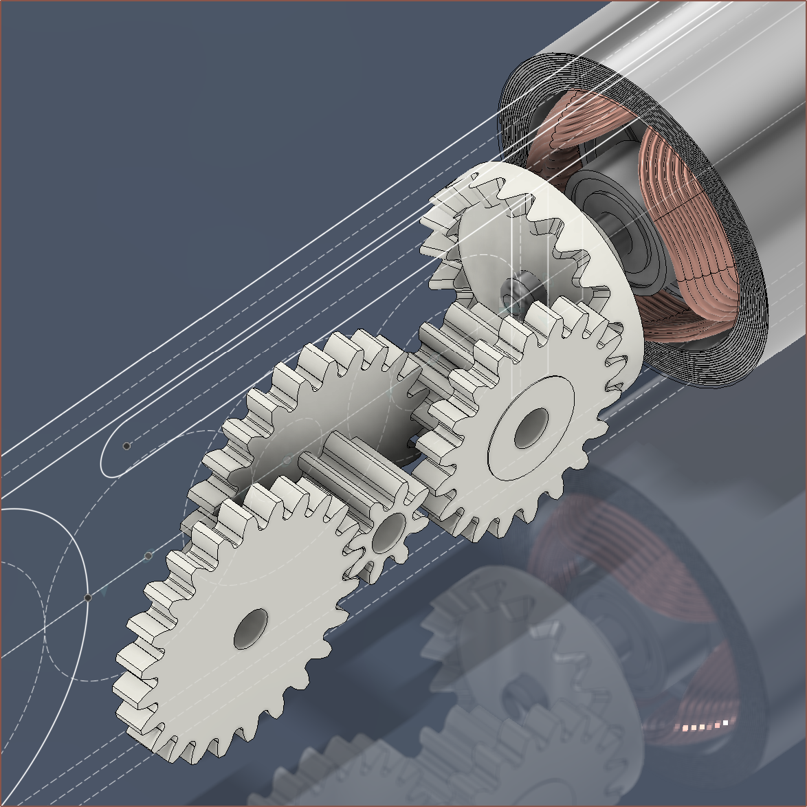
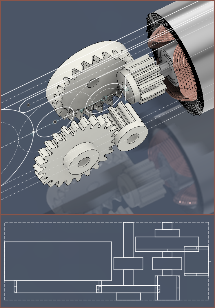
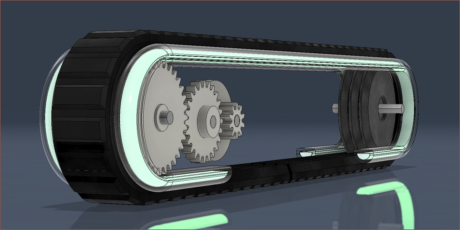
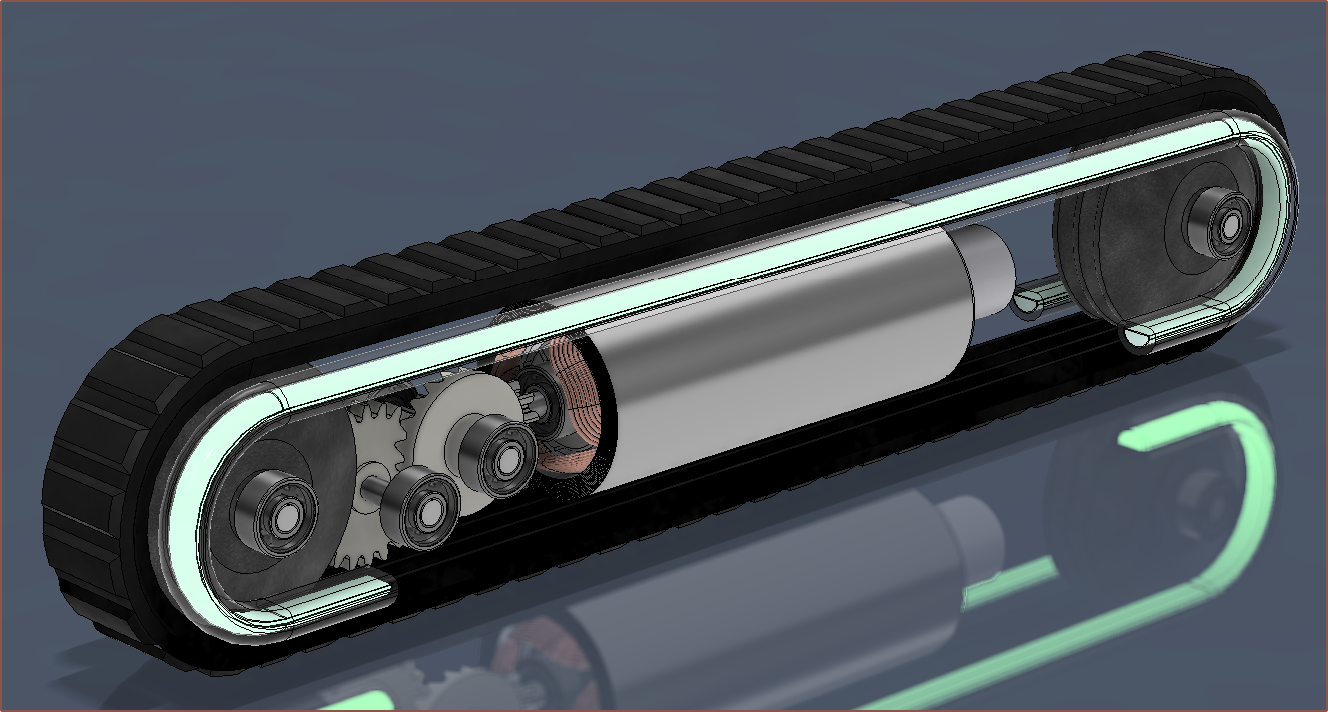
06/29/2024 at 12:05 • 0 commentsExcept for the pulley itself, I've modelled the gears and overall geartrain assembly.
[Jul 09] - I've figured out a more compact solution. This reduces the length by up to 9mm, the specific gears are cheaper (79p savings) and means one less bearing is needed. Due to this, I can now use the more popular and cheaper 4PJ280 v-ribbed belt.
![]()
J102A > C242A > J082A > 242A > 34T for a 10.2:1 reduction. The theoretical top travel speed and power consumption are slightly reduced.
[Jul 10] Against the odds, there just happens to be a dual layer crown gear that has the right number of teeth and fits in the space available:
![]()
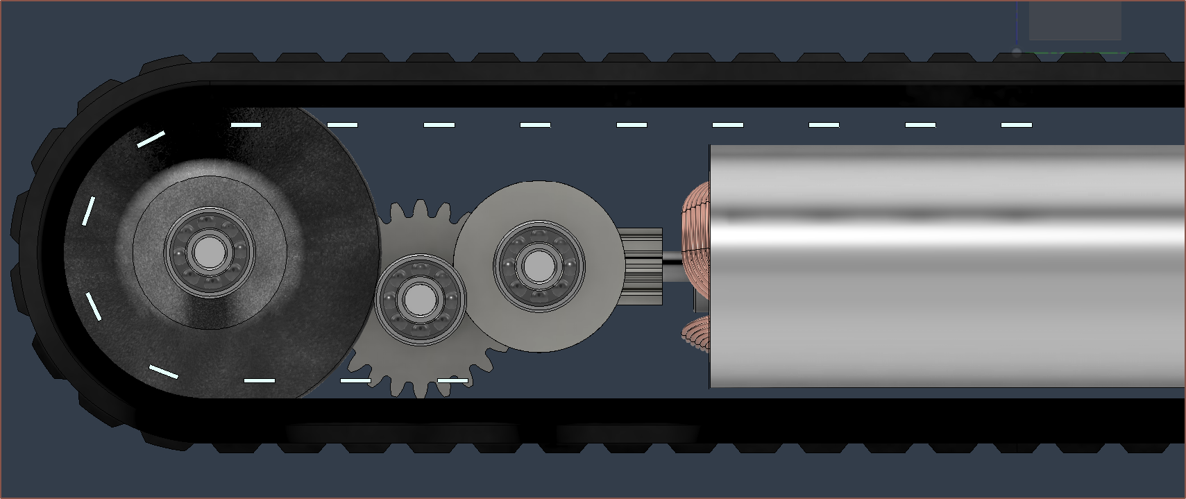
J082A > C24102A > 242A > 30T for 9:1 reduction. It's the C24102A and it's only 0.1mm longer than the space I have. If needed, I likely can file down the tiny excess. This both saves a bit more money, reduces the manufacturing complexity and allows enough space to actually centre the main body portion of #Tetoroidiv [gd0152]!
![]()
Symmetry, one of the foundational pillars of Aesthetic Compliance. Since a 30T on the end pulley still means that the theoretical max power consumption is under 0.2W, I'm going to use it instead of a larger gear to reduce any dogbone-shaped curve of the LED strip around it. A rough drawing of what I mean is below:
![]()
[Jul 11] I've hit some issues that are at odds with each other.
For aesthetic compliance, ideally the LED strip would look like this:
For the total width to be limited to 17mm whilst still protecting the LED strip from the elements, the strip has to actually be slightly under the belt. Unfortunately, this would intersect both the 322A gear and the FSR:
Why is there a 322A gear instead of the printed 30T as planned yesterday? Well, the teeth are so small that it's unlikely going to print with any adequacy, and 32 teeth was more power efficient.
I'd much rather not have to resort to things like 1 strip per Tetrinsic because then the belt won't be centered and it could be visually ambiguous which LED corresponds to which belt. It also notably reduces the future-science vibe.
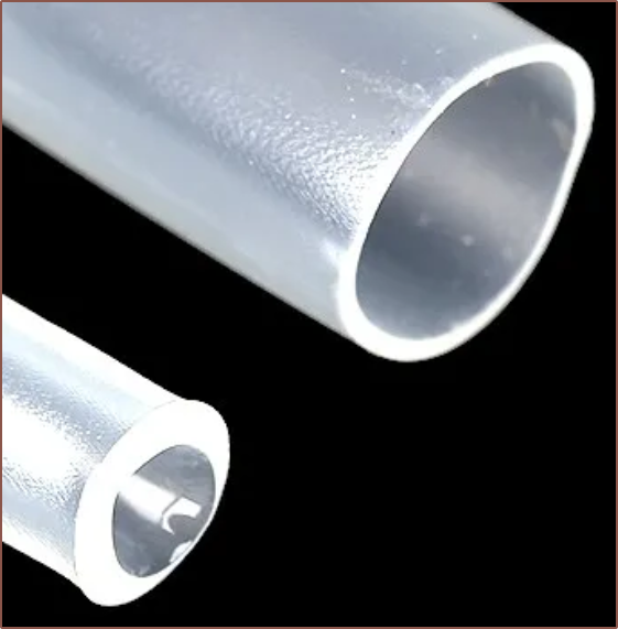
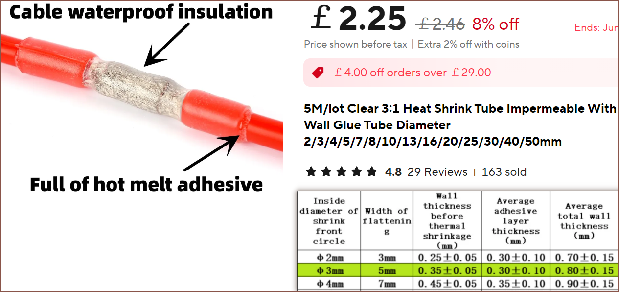
Another issue is that the wall thickness specified in the product listing is for when it's not heat-shrunk. It looks like the waterproofing heat-shrink actually thickens quite a bit after:
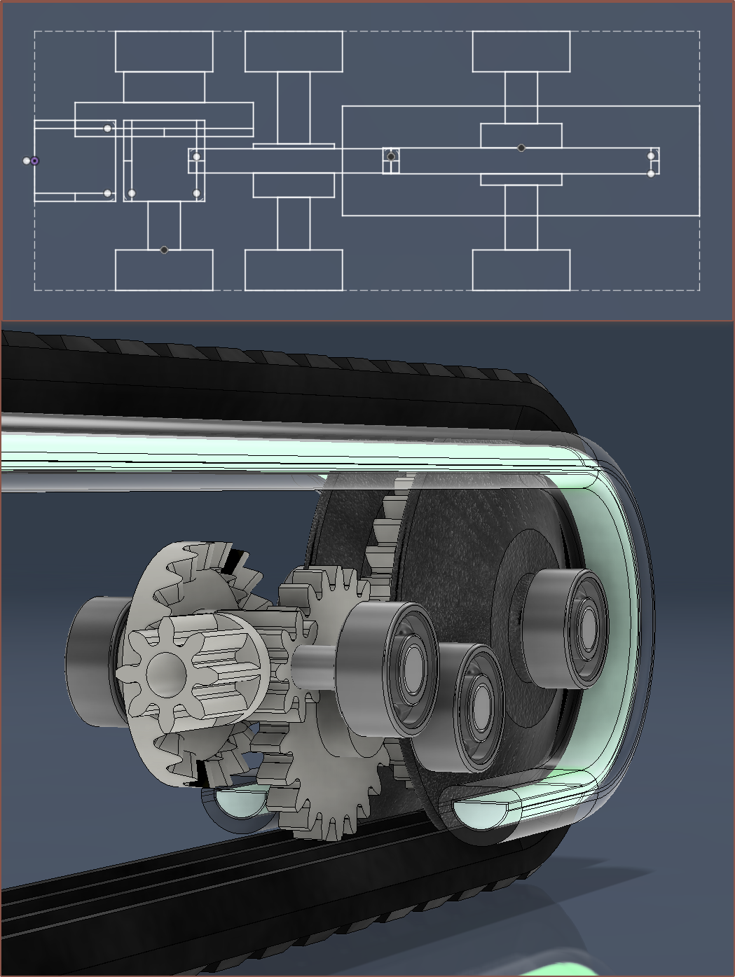
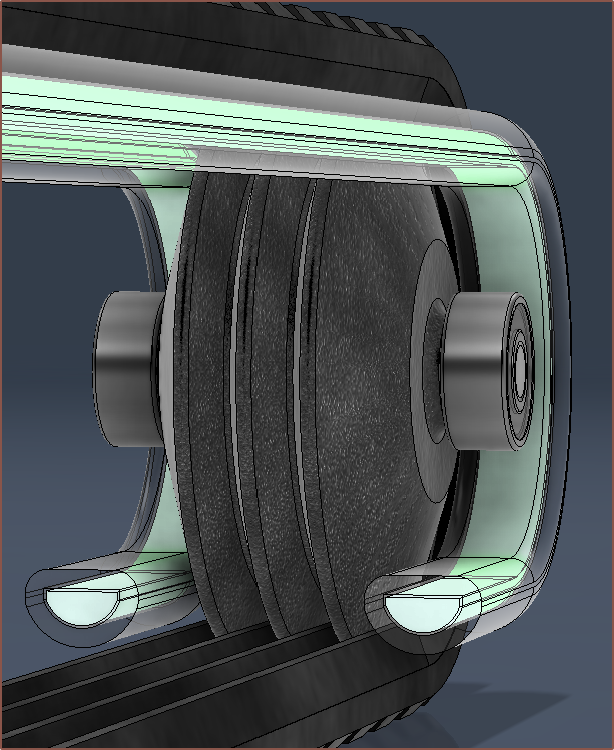
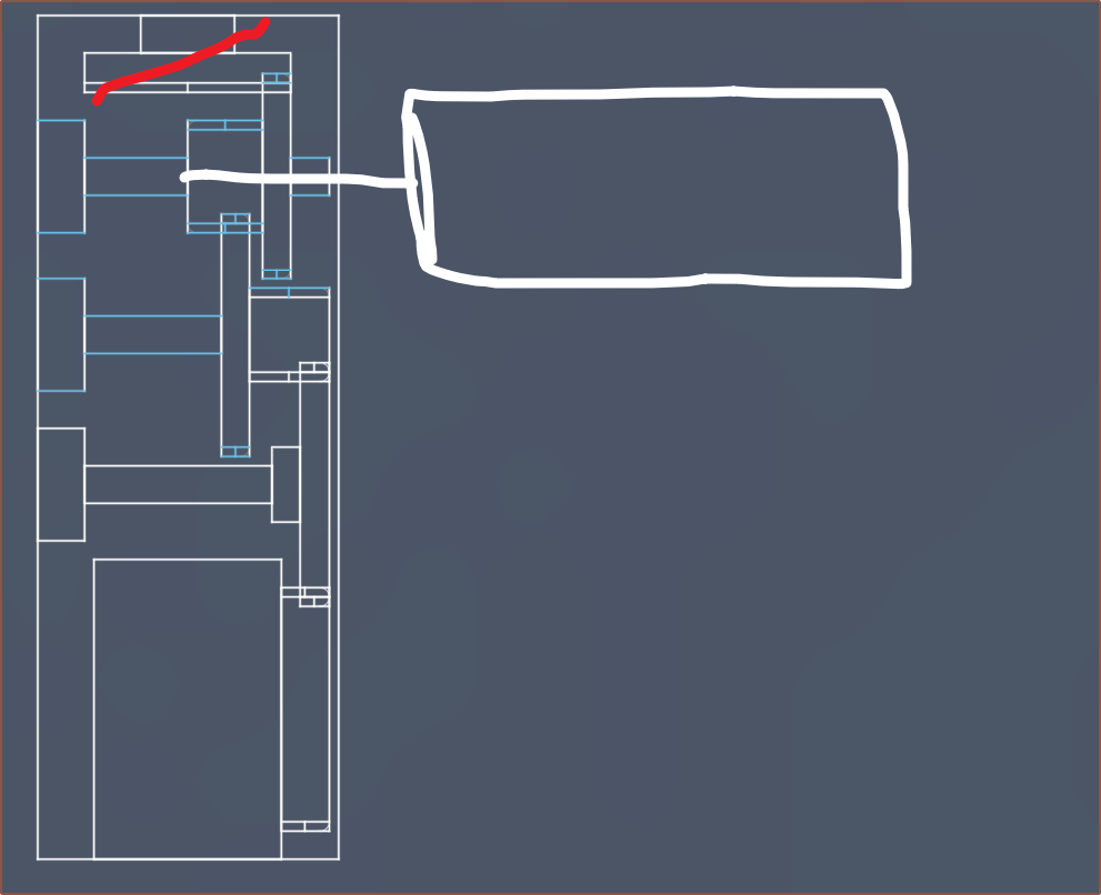
[Jul 12] So I was able to compute a new solution, and there also happens to be enough space (a handful of microns worth) that I can "bend" the geartrain so that the center of the motor stays aligned with the center of Tetrinsic:
The driving pulley is split in two, where the 322A fits inside. The 242A gear is where the tooth gap of the belt is, so hopefully this strategy should be fine. I've decided to use 2pcs J082A so that I don't have to spend time ensuring I haven't accidentally picked up a J102A or vise versa. Lastly, I've gone back to the C202A which allows the geartrain to be a crip 10 : 1 reduction.
I also didn't have confidence that one bearing per M2 pin would suffice, so that's why they're all double bearings now.
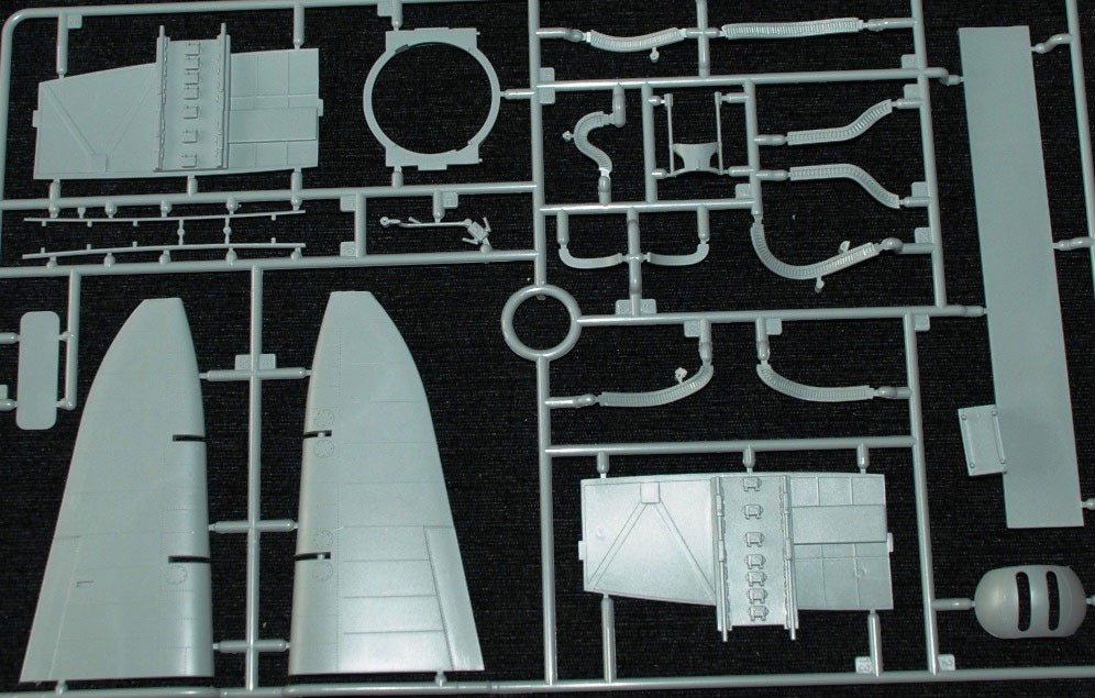
I'm hoping that I can connect all the pulley SLS/MJF prints similar to a hobby kit (see below) so that I can avoid having to spend $1 for each individual part. The other pulley is one solid part:
Ideally, I'd just order one single "part" from JLC and then snip off the connecting cylinders. I've also tried aligning the individual LEDs in the strip. I do hope that a 320LED/m option comes out eventually, because the coverage is rather sparse:
Taking a step back, I'm not sure if designing something that currently looks sci-fi (without it ever being the goal) means I'm on the right track or not, but the coolness is coursing through my veins so I'll just keep calm and carry on.
-
[E1][R] Waterproofing strategies
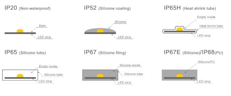
06/19/2024 at 16:09 • 0 commentsOne of the issues with waterproofing Tetrinsic are the LEDs. They're COB, yet still only IP20 rated, and I can't find anything that has a higher rating with similar features and formfactor. So I turned to searching for a DIY solution and found this:
The video can be summarised by this image found on LinkedIn:
To get IP65, the strip has been coated with heat shrink tubing. This tubing exists on AliExpress and sounds like it'll turn a 2.7mm LED strip into a 4.3mm one:
In regards to the PCB, it's probably possible to use shrinkwrap here too as it looks like its what the industry does:
On the other hand, another idea was from the comment section of the below video:
A commenter suggested to use mineral oil. This seems like a nice idea since I'd be able to confirm an airtight seal before this touches water, and the oil will prevent the enclosure from being crushed by water pressure. I then wondered if the MEMS microphone would be ok, but a hacker has actually used mineral oil specifically to make an underwater microphone:
[Jul 13] I'm thinking of using the same M2 pin (as used by the gears) to terminate the side of the LED strip that doesn't have wires connecting to it. I'd need to use multi-core wire so that the adhesive seal works on that side too.
-
[R] Bearings for underwater use
06/19/2024 at 07:58 • 0 commentsThe standard ABEC1 bearings I originally found have questionable tolerances:
I bought the mr52zz Not all bearings have the same internal measurement, I noticed that some are very loose when inserted into a shaft 2mm, being inserted with the hand without problems, others are very tight, and others simply do not pass on the 2mm axis, probably these have to hit with hammer. Please be aware that it may not work on your project.
--- 2-star reviewer on AliExpressAt the same time, I wanted to confirm my suspicions that standard bearings could corrode when submerged in water.
Looking to see what options I had for water resistance in regards to robotics, I watched the following:
Bearings indeed were listed as something that could corrode.
I soon found out about hybrid ceramic bearings, and it's probably not a coincidence why they're advertised for things such as RC cars and fishing reels.
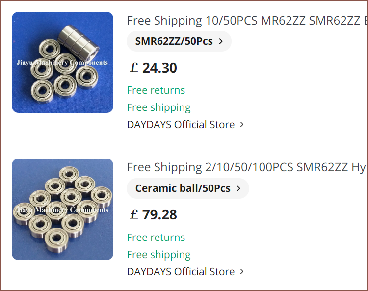
From what I understand, there are 3 options for bearings used in water: stainless steel, ceramic, and a hybrid of the two. Hybrids and ceramics seem to be 3x and 6x the price of stainless respectively.
On my search, one listing essentially said the following for ABEC ratings:
- ABEC1: Low speed, low requirements
- ABEC3: Sub-6kRPM, suitable for motors
- ABEC5: Over-6kRPM, suitable for high-speed motors and precision equipment
Thus, it seems that I require ABEC3 at the minimum. I found some, but I later found some ABEC5's for £1 more (at 50pcs) (see further below).
Ceramic and hybrids are preferable since they use dry/no lubrication. This is useful for both longevity, reducing the "sticktion" and rotational friction. The drawback is that they would add £8/ea to the BOM, compared to £2/ea for stainless steel.
I looked at a rollerskate stress test and the ceramic hybrid was the only one that didn't seize up:
There's also this free-spin test with miniature bearings very similar to the size I'm looking for. They're MR63 bearings, meaning that the only difference is that the inner diameter is 3mm not 2mm. The ceramic bearings were the only ones that needed a 10x timelapse, and the bearings were so low-friction that it was noticeable that the wheel wasn't balanced.
Considering that downtime is problematic, a frictionless sliding experience is highly desired and expected usage is "daily for years", hybrids seem to be the leading choice. To reduce the quantity of bearings needed, I've tweaked the gearing plan so that the moments are reduced:
With this, I'm planning to use 5 bearings instead of 10. However, the price alone is the biggest drawback and the reason why I'm considering stainless steel. -
[B] Unfortunately over £40 each
06/17/2024 at 18:31 • 0 commentsI'm not sure if I ever mentioned it anywhere, but one of my price targets for Tetrinsic was £20/ea.
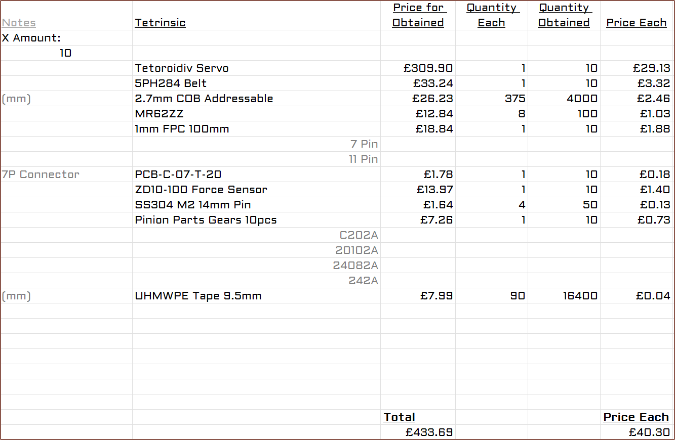
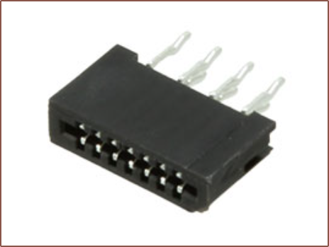
While making this BOM, I determined that it was best to continue the strategy I had for the 11P cable to Tetent by making sure that I can't accidentally solder the LED strip backwards. At the same time, there isn't a 2P FPC. Instead of 2 separate cables, I'm going to use a single 7P cable. This saves both money and simplifies manufacturing. The pinout is below:
- 5V
- LED
- GND
- Force
- GND
- LED
- 5V
Then it's conveniently broken out with this through-hole connector:
This would allow me to create Tetrinsic separately to Tetoroidiv. At this price, I'm further considering the potential for water resistance. The current limitations at the moment are:
- IP20-rated LED strip
- MR62ZZ bearings might be prone to rusting
In other news, this is how close to the wire everything is fitting:
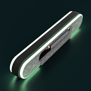
The top flat bar corresponds to the total active length of the force sensor. In other news, I've cobbled together a low-resolution render to finally replace the outdated one:
-
[R] Force Sensitive Linear Potentiometers and ThinPots
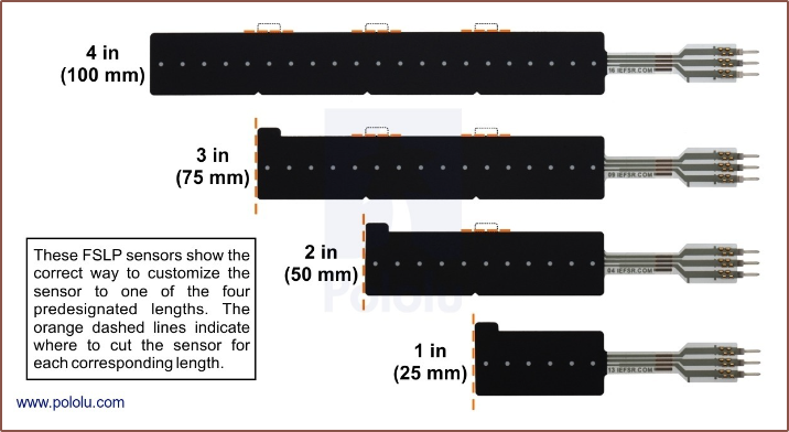
05/12/2024 at 11:21 • 0 commentsSomething I've known about for perhaps a week are these FSLPs:
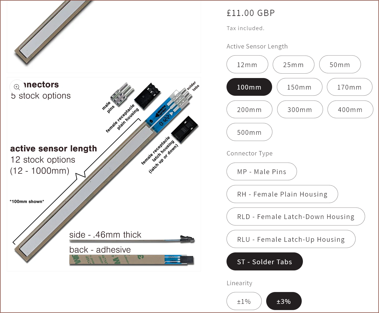
These are the only ones I can find, which are allegedly 100 x 10mm, though the black film certainly looks a lot wider than 10mm.
Today, I've found out that there is a thin-film style of potentiometer, and it seems only one manufacturer makes it commercially:
The ThinPot, a narrower version of the SoftPot. I also assume that, unlike FSRs and the aforementioned FSLP, it's not cuttable.
Below, I found some videos of people layering these pots ontop of an FSR:
While I think it would be nice to be able to just touch anywhere on the belt and Tetrinsic can sense exactly where, I see it as an added luxury considering that the price would be a considerable percentage of the BOM and the position in day-to-day use is already acquired via the magnetic encoder on a motor.
-
[M] Gearing strategy of 7.2:1
05/07/2024 at 12:54 • 0 commentsThe new gearing strategy (including the 16mm pulley). It's 45mm end-to-end. Everything has at least 0.5mm tolerance for non-meshing locations. The gear reductions blend the domains of Tetrinsic and Tetoroidiv together, and since the gears themselves are likely to be mounted on Tetrinsic, I'm writing the log here.
I started looking into it because I thought "If I could get 2x the reduction, I could use the 1-pole-pair solution. with a 40mm rotor".
So after going through Pinion Parts Store on AliExpress, this is the compact solution I landed on after about an hour:
"Mkay... that should be a 15.6 : 1 reduction. Bit high but maybe it's ok?" Then I started sketching the other gearing strategy planned to be used with a 58mm rotor. It was then that I realised that I just assumed "smaller number over bigger number" for the gearing calculation, and that the gearing ratio wasn't 2.6 : 1, it was 0.78 : 1! This was me when I put the new calculation into the Excel spreadsheet and saw the wattage numbers of motors such as Toroid-58mm and the 1656:
So I already weakened after that realisation, but the "Instant Damage" potion that took me down to "half-a-heart" (speaking in Minecraft terms) was when I then looked at my gearing strategy again and realised it's all backwards! I had created a 1-to-16 torque destroyer!
It took me over 12 hours to recover from that emotional damage yesterday.
Knowing that all the 50mm+ motors I had found now weren't going to fit, I went looking around. Most of the motors I found in the sub-40mm range all used 2mm shafts, and I can use a C202A for that.
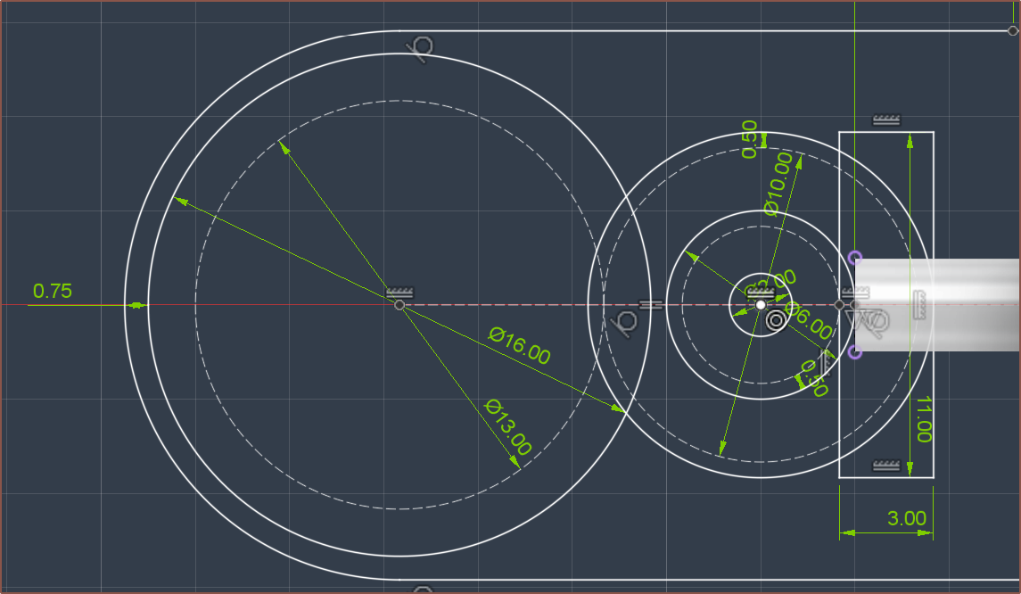
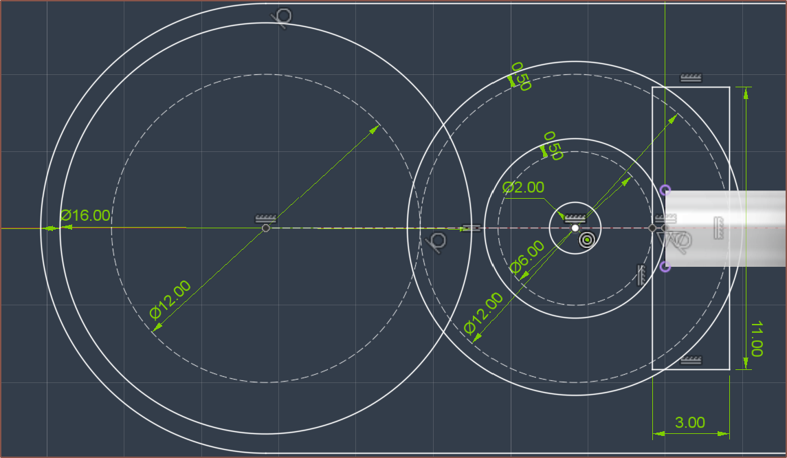
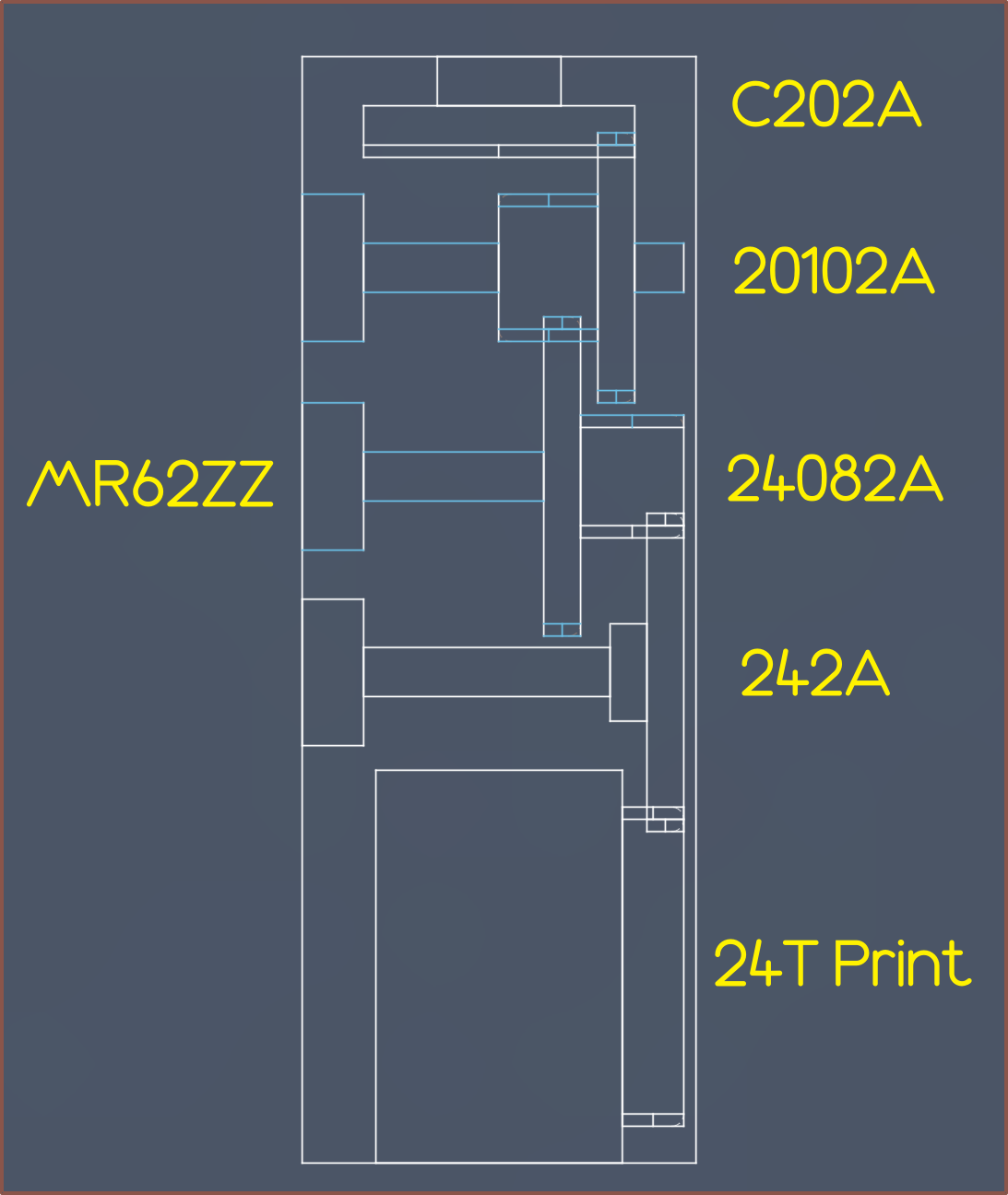
Today, I've converged on the following 16mm-wide solution, providing a reduction of 7.2 : 1:
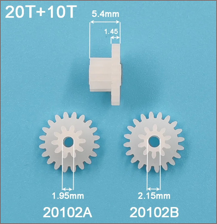
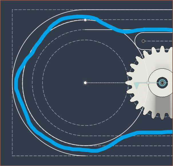
It might also be possible to integrate the 242A into the print so that the teeth don't have to be printed. Also, not sure why Fusion wants to colour some lines blue when the sketch is fully defined. I've also learned how to read the names. 2A means "2mm shaft, tight". Then it's just listing one or both teeth counts. For example "24082A" means "24 teeth connected to 8 teeth. Tight fit on 2mm shaft.". "C" stands for "crown".
Additionally, the idea is to potentially use the same bearings inside Tetoroidiv, as well as omit the crown gear and connect the motor directly to 20102A for the thumb Tetrinsics.
The current centre-to-centre spacing between the proposed motor location and the pulley is 28.5mm, which should be enough to put the thumb Tetrinsic motor right beside the finger ones and still allow a square form factor. The height of the gearing is defined by the largest gear, so that's why there are many with the same 24 teeth. The length of the gearing could be shortened slightly by using 18102A -> 22082A -> 222A -> 22 teeth print.
-
[E2][T] Spin-off motor, PCB and UV LED?
04/29/2024 at 15:59 • 0 comments- Looking at my options, i think the best thing to do now is make a prototype that doesn't include a motor.
- This would also make it easier to implement if someone just wants to have an LED lit, force sensitive but otherwise basic slider, similar in nature to the encoders installed in some hobbyist keyboards.
- At least if literally everything else about the current concept works, it would be easier to justify £50 and up for a prototype motor or spending days making my own.
- [E2] The proposal... fails. I need a haptic source, where the lack of which was partially responsible for the non-use of #AirBerries and SpaceExplorer
- I've created project #Tetrinsic Toroid [gd0152] which would contain the BLDC + PCB.
- [E2: May 1] - Renamed to a trendier "Tetoroidiv" to keep with the coincidental tradition of an ever so slightly longer name on each subproject;
- Move the UV LED out of Tetrinsic's domain
- I've computed a new Tetent solution, and started on an Itinervate one too, and it seems that the LED would be better mounted on the enclosure or PCB mounted with Tetrinsic, and not something to bundle along with it.
- The above is the potential Tetent solution side profile. The top/right orange part is the belt, and the left orange is an LED that just lines up with the ones on Tetrinsic to give the illusion that it's continuous. In actuality, this curve has the 21700 cell.. The grey lines is supposed to be a 3D texture of diamond squares.
- [E1] Cleaner, 1:1 sketch:
I'm calling this Concept Solution Epsilon, named after the Overlord character, because it's a potential solution and I wrongly thought ' Σ ' was capital epsilon until I looked it up right now.
- Additionally, water resistance becomes mandatory.
- I need to get "that 99.9% uptime". What I mean by this is that I want to be able to use it in 99.9% of reasonable situations. Thinking through thoughts during a shower or while running in the rain between locations is what I'd call a reasonable situation.
- I think there's a notable and valuable gain from the difference between a 90%, 99% and 99.9% solution.
- [E1] Unfortunately, the COB strip is IP20, so not off to a good start.
- Looking at my options, i think the best thing to do now is make a prototype that doesn't include a motor.
-
[E1][T] More accurate power estimates
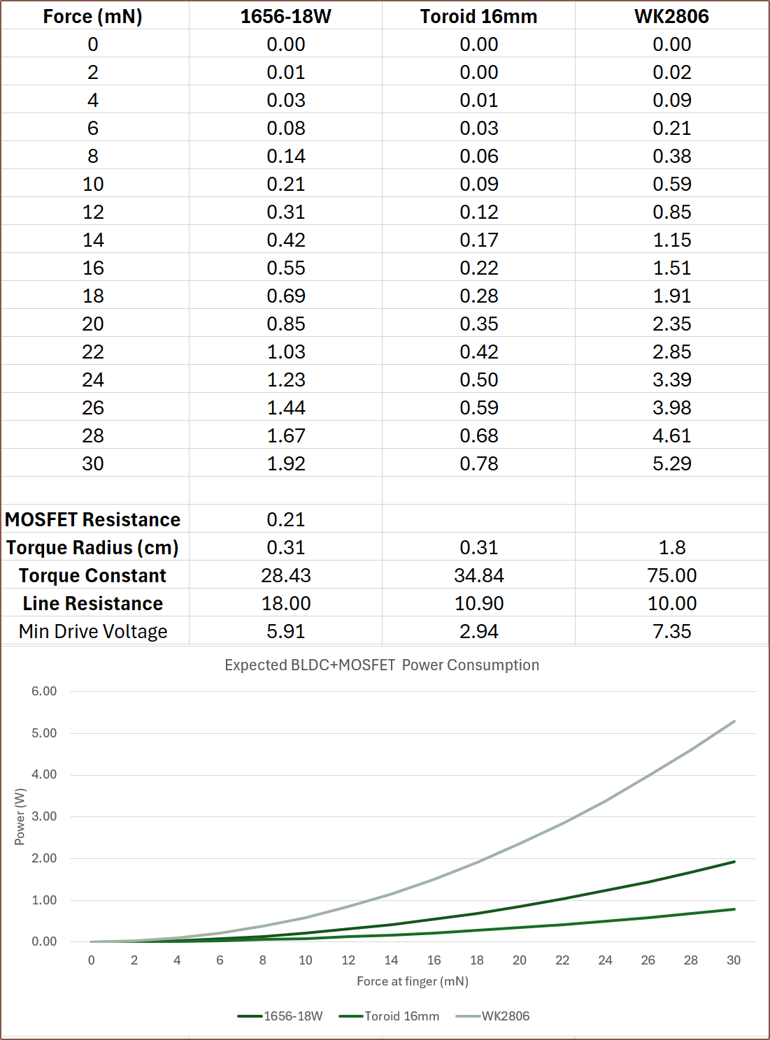
04/29/2024 at 07:45 • 0 commentsSo I've added torque radius into the equation, which essentially is the effective radius of the force if there was no gearing or reductions. This paints a very different picture now that there is a 2.6 : 1 reduction for getting the power from the motor and into the belt.
Additionally, my current understanding that, all else being equal, the proportionality of rotor radius, rotor length and number-of-turns is quadratic, linear and linear respectively. Thus, I've calculated the expected torque constant difference from the motor mentioned in the paper with a 40mm long rotor and 78 turns. There is barely enough space for a 50mm rotor and that would increase the torque constant to 43.5. This calculation assumes that a 4-pole rotor can be obtained. I'd expect less torque if using the 2-pole magnet I found on aliexpress.
The $32 1656-18W motor also now has more favourable power consumption now.
I'll have to see what the torque numbers are when at the new max expected speed of approximately 1200RPM.
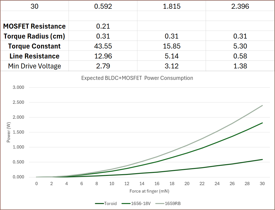
[Apr30] So I can see the amp-turns in action. I can fit 36 turns at 0.25mm diameter, 78 at 0.18 and 106 at 0.15mm, and with a 50mm rotor, they all get essentially 0.6W peak when putting in the resistances and compensating the amp. The only thing that changes is the minimum drive voltage, dropping down to 1.29V for the 36 turns configuration.
Thus, I think the strategy needs to optimised from other perspectives. For example, If I aim for a minimum drive just under 3V, such as the 78 turns configuration, I could use the battery voltage directly. I'm already planning to read the currents drawn by the motor, thus I'd save on voltage conversion losses. With this in mind, the 18V version of the 1656 makes more sense:
I've shuffled the order and added in the 1659RB motor mentioned in a 4th edit a few logs back. -
[R] 9.6mm V-Belt
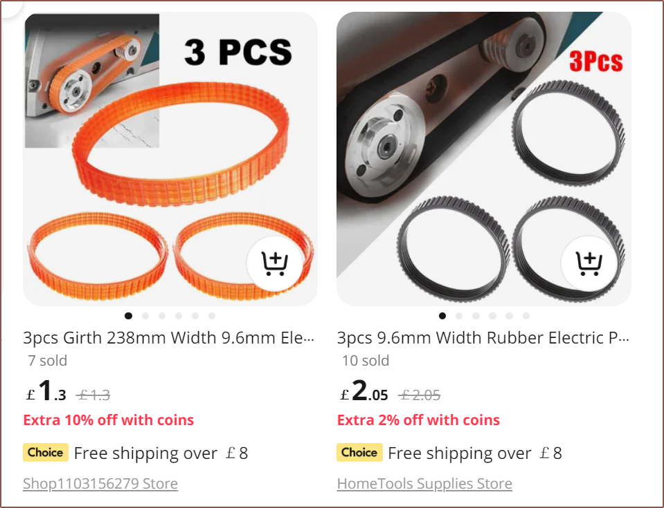
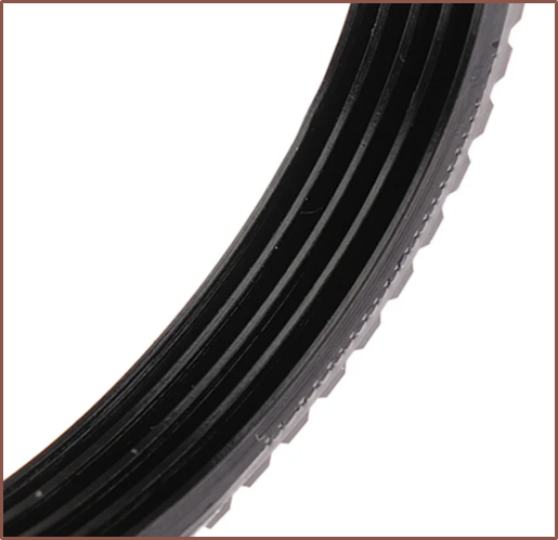
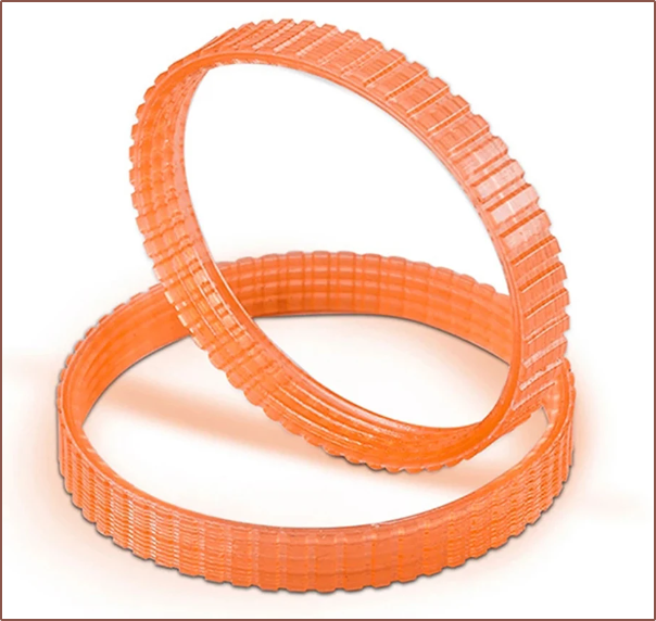
04/28/2024 at 15:10 • 0 commentsFrom the sketch I showed in the previous log, Fusion says that the belt length I need is 237.98mm... essentially 238mm. So I just searched "238mm belt" and coincidentally enough, such belts exist:
I've seen these belts before. I just didn't know that they specifically came in 238mm loops.
The black ones come with a thick looking groove on the underside, which is probably good for the sliding straights but not exactly ideal for the gear-teeth pulley.
The orange ones are slightly cheaper, and because they transmit more light, it's much harder to guage if the underside profile is the same as the black, but it's probably safe to assume so. What I do know is that the black one is rubber and the orange is polyuetherane.
The one standing almost looks like an optical illusion. Unfortunately, both of these are 3.2-3.3mm thick, which is almost double the thickness that I'm looking for.
It looks flexible enough:
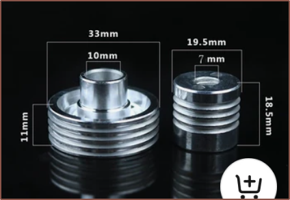
Looking at what this belt attaches to, the minimum turn radius might be OK if the smaller pulley is 19.5mm:
It also seems self-centering, meaning that I wouldn't need the flange and so I could probably tweak the gears to use something like this:
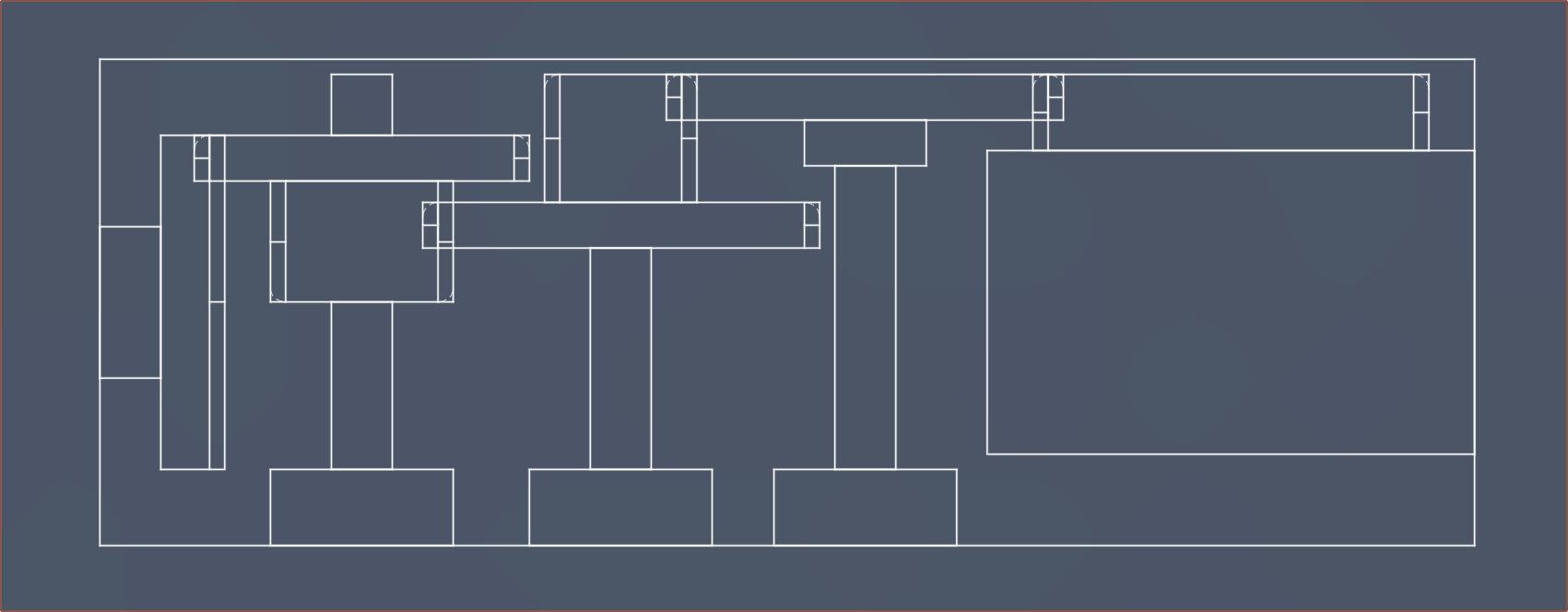
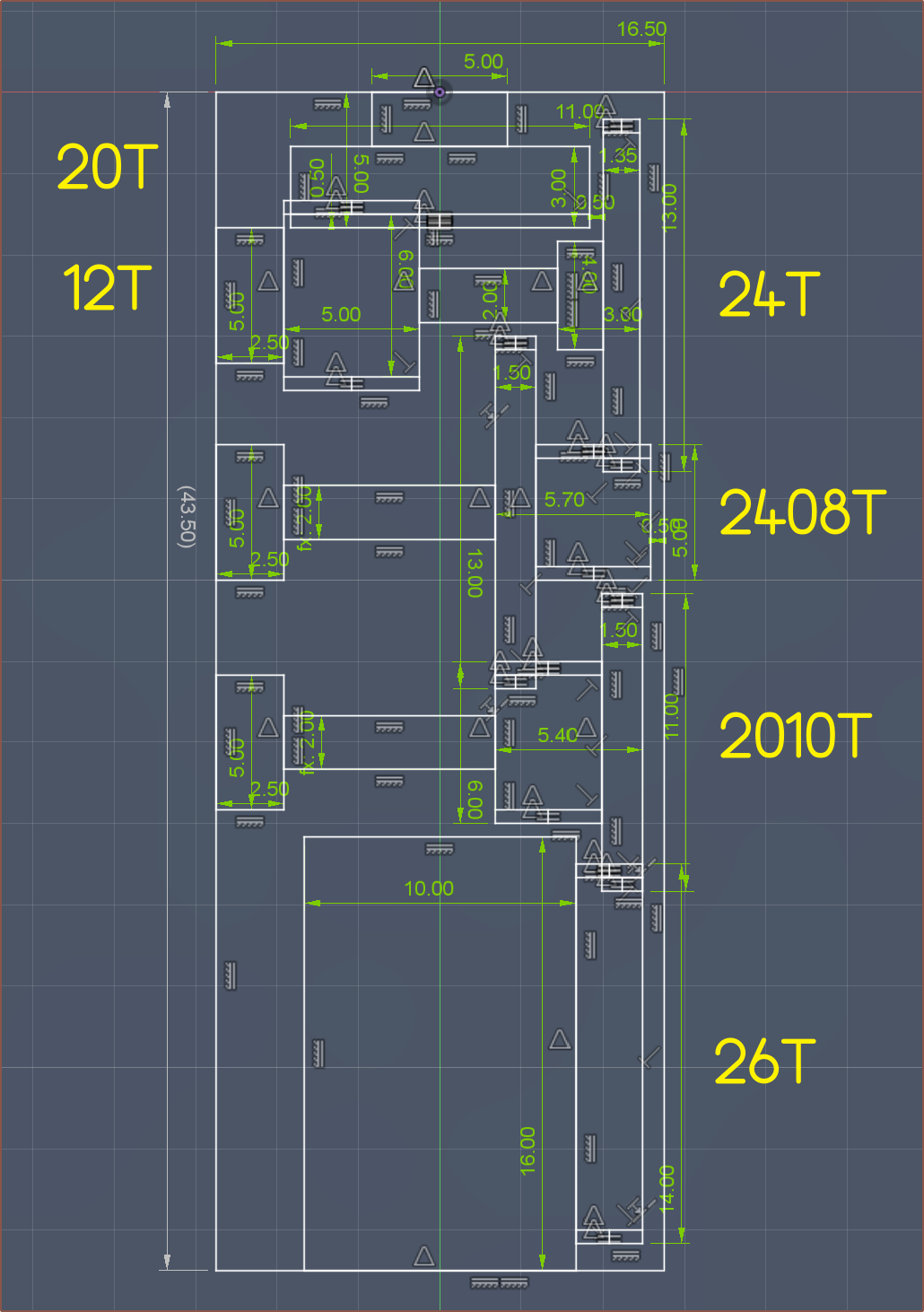
20T crown -> 10T+20T -> 26T+pulley 12T+24T keeps ratios in nice integer values, though I can't find a tight-fit variant:
The final height is 24.5mm, which isn't ideal but doesn't fail any downstream solutions.
Tetrinsic [gd0041]
A motorised fader that is continuous, pressure sensitive, haptic and water resistant.
 kelvinA
 So I've recently designed the
 Except for the pulley itself, I've modelled the gears and overall geartrain assembly.









 It also seems self-centering, meaning that I wouldn't need the flange and so I could probably tweak the gears to use something like this: