-
[M] Fixed-Free Leadscrew Z Axis
08/02/2022 at 16:48 • 0 comments![]()
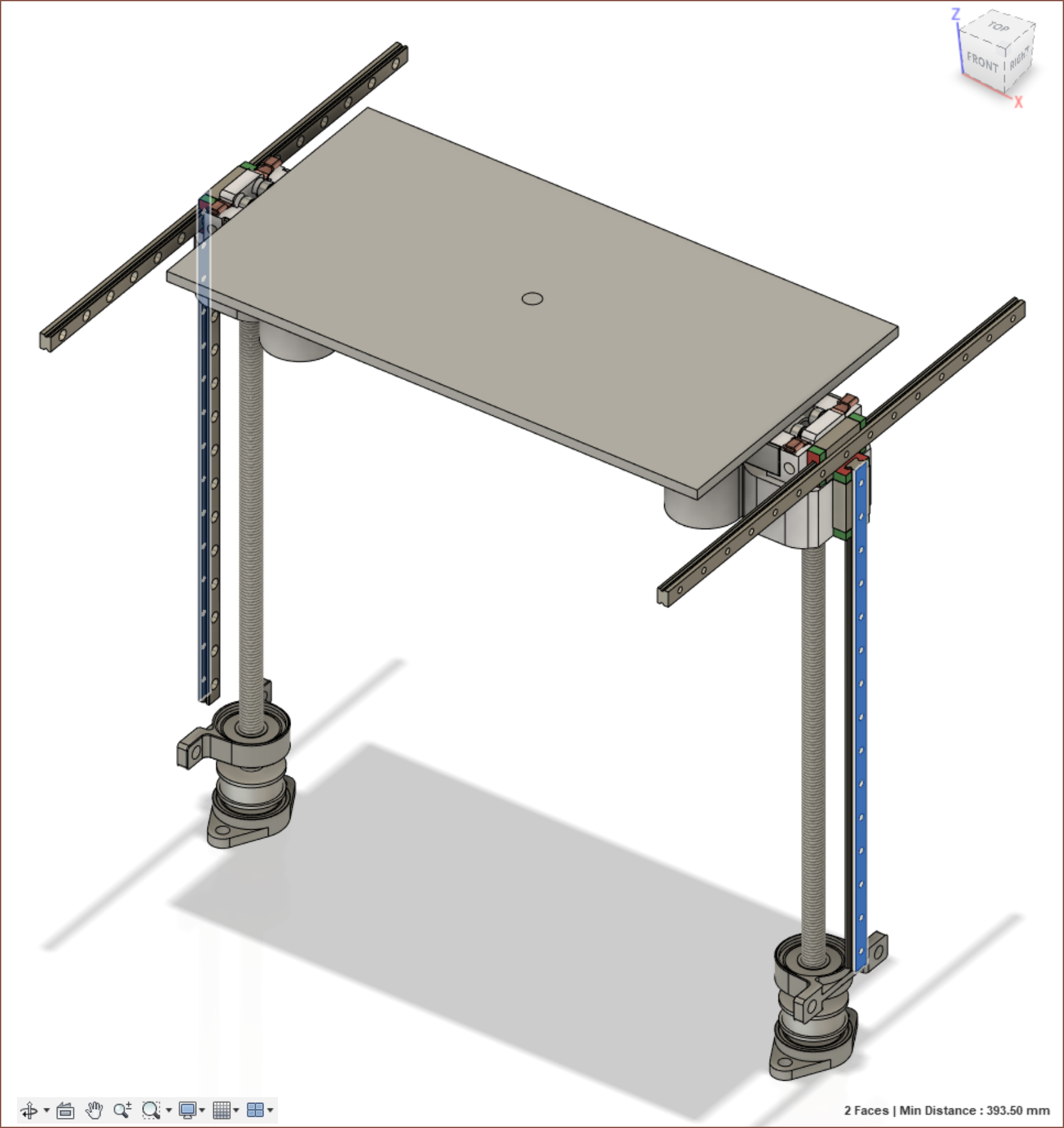
Yesterday I was trying to fit the Small Z axis into a bounding box to determine what the footprint is most likely going to be, as well as comparing it with the currently recommended budget printers. Considering that the printer is likely going to be north of £649, I decided to go for better value; an analogy is that I'd rather have a slightly more expensive but filling meal than a slightly cheaper but not filling one.
Me in 2018's minimum and recommended requirements for an MSLA printer volume was at least 200mm in 2 of the 3 axes and ideally 300mm in X and/or Y, so I've increased the bed to 3 screen-areas (307.2mm) and the Z by 50mm to obtain around 230mm of Z height. This is a print volume that could fit a better percentage of my projects and files online (since they'd be designed for something like a 220mm bed in mind). The expected footprint is now expected to be 540x305x600mm.
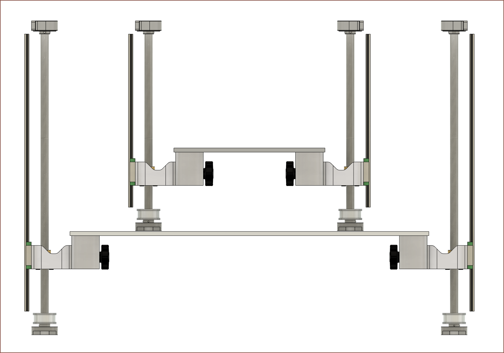
![]() I accedentally forgot the X axis linear rails and to make sure that the spreadsheet calculated the extra 2 roller rails, so the difference in price between the 204.8*163.6*170mm and 307.2*163.6*230mm is only expected to be a sub £10 difference: £6 for the longer bed and pennies for the longer leadscrews and linear rails.
I accedentally forgot the X axis linear rails and to make sure that the spreadsheet calculated the extra 2 roller rails, so the difference in price between the 204.8*163.6*170mm and 307.2*163.6*230mm is only expected to be a sub £10 difference: £6 for the longer bed and pennies for the longer leadscrews and linear rails.As you can see from the top image, I've decided on a fixed-free leadscrew mounting arrangement. I put the values for the Suspense in an online calculator and it said that the critical speed was over 270mm/s, which I don't plan on exceeding. This arrangement allows for a smaller X footprint and smaller Z axis mount that doesn't have the roller rail cutout through it.
-
[M] Second Belt on Roller Rail Mount
08/02/2022 at 15:33 • 0 comments![]()
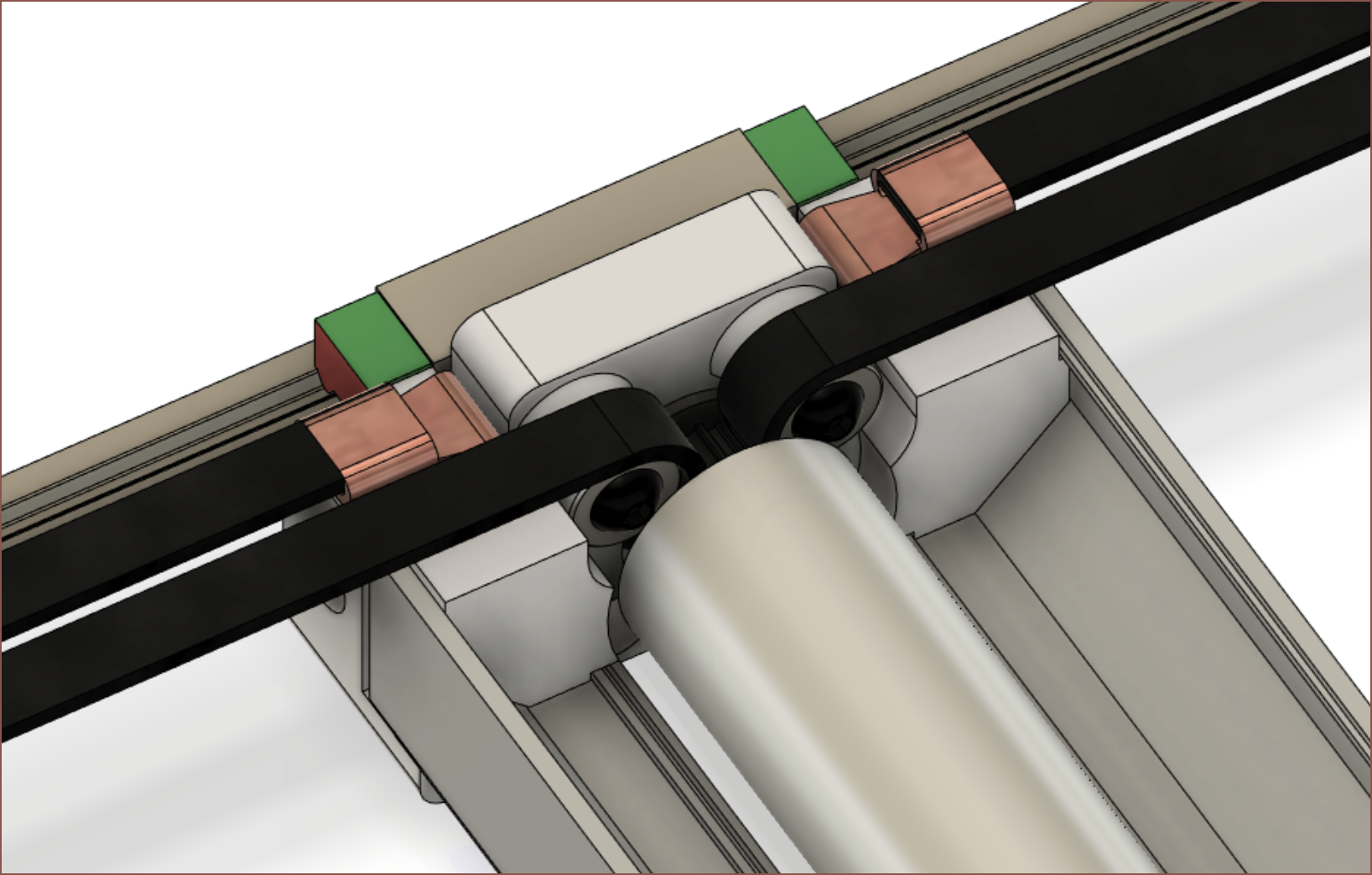
I was thinking of going with a fixed-free mounting solution for the Z axis to gain some more favourable part alignments and decided that I needed to implement the way that the second belt was mounted. There isn't much space so I found some copper crimps on AliExpress and have modelled a bent one to fit inside the available area. The clamp has increased 3mm in the distance from the rail to the roller.
-
[A] [T] Current BOM Price (and more scanner sensors)
08/01/2022 at 05:44 • 0 comments![]() I've added in a few components, such as SuspenseSmall exclusives and new things like the 10 contact image sensors. Oh right I haven't mentioned it in the previous log, but I'm thinking that there would be a real benefit on debug/testing and features (explained below). I've also seperated the quantities into Suspense and SuspenseSmall so that it's possible to track an estimate to either. The Small will likely cost more if components were sourced by themselves.
I've added in a few components, such as SuspenseSmall exclusives and new things like the 10 contact image sensors. Oh right I haven't mentioned it in the previous log, but I'm thinking that there would be a real benefit on debug/testing and features (explained below). I've also seperated the quantities into Suspense and SuspenseSmall so that it's possible to track an estimate to either. The Small will likely cost more if components were sourced by themselves.Since each sensor is about £4 after tax and another hackaday user managed to get a fraction of data off of it (see the log comments), I'm just going to assume that it'll work fine. With this assumption, I'm thinking of adding a sensor to each side of the LCD head which will allow these possible features:
- Verifying/Inspecting the current layer and cleaning performance.
- This would likely be much better than eye-balling or taking smartphone pictures. It has the equivalent function of the 330fps camera for the #SecSavr Sublime [gd0036] .
- Timelapse
- The scanners apparently have RGB LEDs in there, so a status indicator
- Receipt and A5 document scanner
Additionally, one sensor could be put inbetween the area where PnP components are stored and the build area so that the arm just has to swipe anywhere in the 210mm scanning area for the computer vision software to obtain an image, thus hopefully the arm is already in place by the time the software has calculated the rotational adjustment needed. It may be possible for the X axis to scan the just-placed part to confirm that the component was placed correctly, but a component might be sticking out in the Z and damage the screen
- Verifying/Inspecting the current layer and cleaning performance.
-
[R] Contact Image Sensor for coating detection
07/31/2022 at 21:31 • 0 commentsI was actually looking at a project that desired to 3D print by scanning a laser dot over the vat when I thought that I should see if I could implement some kind of sensor to scan the applied layer on the PET film. This is to allow the printer to detect a coating issue so that it can recoat. If there are consecutive fails, it means there's an issue such as an empty cartridge.
I still can't figure out what module Bambu Labs uses in their new printer, considering even the "micro LIDAR" modules I found on Aliexpress start sensing at 10cm and cannot get Bambu's 7um accuracy.
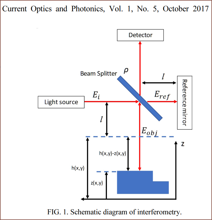
I wanted to see if I could get both a scan of an opaque+transparent layer and a measurement of the thickness. If both features were in the same sensor, that would be even better. I looked to the research papers with search terms like "thin film coating measurement" and "non contact thickness detection" and a process called interferometry came up a few times.
![]()
https://opg.optica.org/DirectPDFAccess/549439B3-F979-42AE-913D9114491F729C_376548/copp-1-5-505.pdf?da=1&id=376548&seq=0&mobile=no The papers seemed a bit over my mental compute budget, so I went back to just thinking about getting a scan of a layer. The area to scan is 17cm and most scanners are for 21cm A4 paper, so I looked for a "scanner sensor". I found out that they're called "contact image sensors" and I've always wondered what they were called ever since 2017 when I found out about handheld A4 document scanners (that are still at the same £30 I remember).
It seemed that there's no off-the-shelf sensor and the only sensors are understandably repair parts for old all-in-one printers. Thus, the requirements for my search were that the sensor was cheap and abundant. I think I've found something: Q8100-60002
![]() I've looked into some of the printers listed and they all seem to be over a decade old, so I'm suprised that there's still so much part stock today.
I've looked into some of the printers listed and they all seem to be over a decade old, so I'm suprised that there's still so much part stock today.![]()
Anyway, when it comes to interfacing with something proprietary from a manufacturer, there's likely going to be all sorts of hurdles. I've found this log on hackaday.io but haven't looked into it in detail. I'm just going to design the Suspense with this in mind and deal with the complications at a later time. Regarding the light source, I'm thinking of possibly using a yellow tape like Kapton to reduce the blue light hitting the UV resin. I hear daylight LEDs cure the resin extremely slowly though, so perhaps this wouldn't be needed.
-
[M] Optimised Bed Assembly
07/31/2022 at 11:10 • 0 comments![]() By moving the roller down 10mm, I've been able to move things around so that the small bed assembly is 348.5mm wide. Z height for the Small is 175mm.
By moving the roller down 10mm, I've been able to move things around so that the small bed assembly is 348.5mm wide. Z height for the Small is 175mm. -
[M] Roller and bed assembly for Small
07/31/2022 at 04:13 • 1 comment![]() As you can see, I've redesigned the Z assembly to use the T12 leadscrews instead of the ballscrews. 5M 20T pulleys are used because they're cheaper than 3M from the AliExpress seller I found for some unknown reason. For bed alignment, I'm opting for 2-point 1 rotation levelling. There should be 1cm of clearance to remove the M8 star bolts.
As you can see, I've redesigned the Z assembly to use the T12 leadscrews instead of the ballscrews. 5M 20T pulleys are used because they're cheaper than 3M from the AliExpress seller I found for some unknown reason. For bed alignment, I'm opting for 2-point 1 rotation levelling. There should be 1cm of clearance to remove the M8 star bolts. A SuspenseSmall roller assembly has also been created.
The current allowable Z height is 334mm for the Suspense and 185mm for the SuspenseSmall. These could be increased by 7mm if the rails were 7mm longer. The Small footprint height is expected to be around 500mm.
Being able to share components reduces the additonal modelling time for the SuspenseSmall.
-
[T] Building both the Suspense and SuspenseSmall
07/30/2022 at 21:29 • 0 commentsI'm currently implementing the T12 lead screw into the design and have removed 4 linear rails from the BOM, saving around £40, so I think £1099 - 1199 is still in the cards, but I've remembered scrolling though Discord and Reddit comments about what printer they should buy / just bought and $500 came up often. Additionally, unless it's a TV or a table, consumers don't usually have a free 1.2m cuboid volume to place the SecSavr Suspense.
I was thinking that a solution could exist under £400 (spoiler, it can't) for a SuspenseSmall that shared many of the Suspense components so that:
- a) I could save on my BOM through bulk pricing and lower per-part shipping fees,
- b) hobbyists could "dip their toes" into the technology without spending £1200 (or more if they don't have a CR10 sized printer),
- c) it could fit alongside a kitchen appliance,
- d) better project publicity, and
- e) I could have a tester printer and have more than 1 data point to validate settings and research.
I did some quick addition and it's looking to be heading for £649 when "the unknown" is taken into account.
![]() This is for a SecSavr SuspenseSmall with the following specifications:
This is for a SecSavr SuspenseSmall with the following specifications:- 108W UV LED (this takes up about 200mm of Z height though, compared to 90mm for an array)
- 7.6" 4K+ Mono screen for a 40um pixel size
- 395*305*395mm footprint
- 204.8*163.6*[some Z height likely under 200]mm build volume
- Dual colour
I will take any opportunity to sping to quad colour support if physics allows. If the Suspense works as intended with dual colour, it'll already be a strong competitor to the Photon M3 Plus that's also at £649 on Amazon, but white, black, support and transparency would allow something closer to consumer's original expectation of 3D printers a decade ago, but in greyscale. The SecSavr Small (shortened name) and the SecSavr Suspense would be a similar setup to the cheaper B+W laser printer and the more expensive but full colour laser printer.
-
[M] UV LED 108W
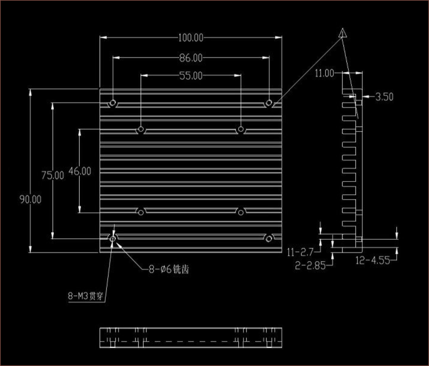
07/30/2022 at 13:46 • 0 comments![]() The heatsink is the most important, with these dimensions provided by the seller:
The heatsink is the most important, with these dimensions provided by the seller:![]() I more or less "eyeball-ed" all the other components, and the height comes to 46mm, so I belive I'm close.
I more or less "eyeball-ed" all the other components, and the height comes to 46mm, so I belive I'm close. -
[R] Multi Material SLA
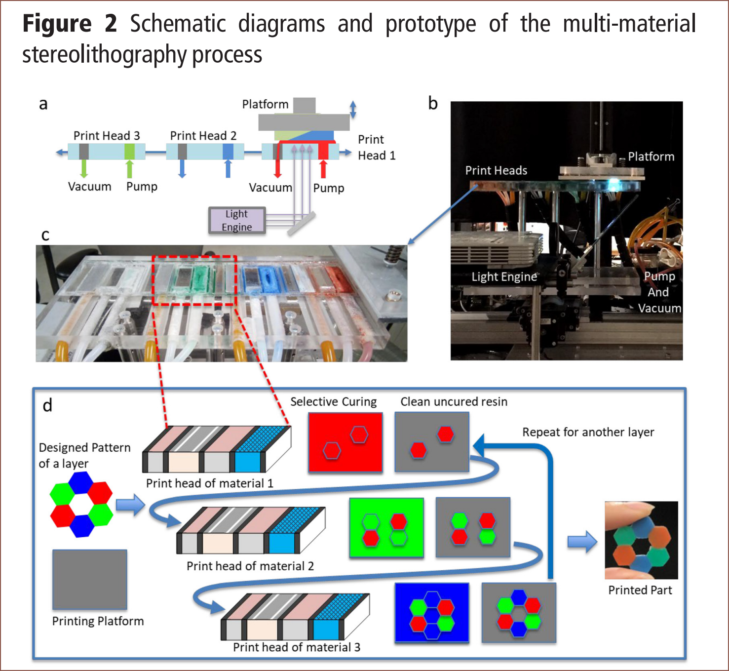
07/30/2022 at 04:01 • 0 commentsI've discovered a paper that is currently the most similar to what I'm trying to do now, published just over 12 months ago:
Multi-material stereolithography using curing-on-demand printheads
![]()
The researchers have the resin go through a mesh, cure with DLP, vacuum the excess resin and then do final cure before moving to the next print head. At least this gives some sort of confirmation that a multi material SLA can be built 1 colour at a time. The researchers call it "cure on demand" and this is their second time trying, though it does seem to have a low build volume : footprint.
The first time is Digital material fabrication using mask‐image‐projection‐based stereolithography, where they place everything on a disk:
![]() They used shallow vats that needed a minimum of 0.5mm of resin due to surface tension. I'm targetting for as low as 0.05mm. Hopefully, that would eliminate the need of the second cleaning step in their 2 step process:
They used shallow vats that needed a minimum of 0.5mm of resin due to surface tension. I'm targetting for as low as 0.05mm. Hopefully, that would eliminate the need of the second cleaning step in their 2 step process:![]() I'm not using a brush because I don't think that they could be cleaned over the course of an average print job. I'd like to avoid solvents due to VOCs and because of the drying requirement that they also mentioned. The vacuum from their more recent work could be an option, but they're loud and I have a 510mm span to cover. An option could be to move across the X axis, reducing the span to 168mm, but then there's the uncured resin cleaning job inside the vacuum gear to contest with, which I'd imagine would be more complex than curing a saturated thread. Speaking of the thread, I have thought about wiping the part with it directly, but I worry about consumable consumption and the thread getting caught on the print.
I'm not using a brush because I don't think that they could be cleaned over the course of an average print job. I'd like to avoid solvents due to VOCs and because of the drying requirement that they also mentioned. The vacuum from their more recent work could be an option, but they're loud and I have a 510mm span to cover. An option could be to move across the X axis, reducing the span to 168mm, but then there's the uncured resin cleaning job inside the vacuum gear to contest with, which I'd imagine would be more complex than curing a saturated thread. Speaking of the thread, I have thought about wiping the part with it directly, but I worry about consumable consumption and the thread getting caught on the print.They've even tried out dithering. For their attempt in 2013, the results seem somewhat all over the place.
![]() Perhaps the reason is due to this note they made in their conclusion:
Perhaps the reason is due to this note they made in their conclusion:![]() The potential for air cavities is the reason why I hypothesise that the smallest "colour island" would be 80um+ instead of 40um.
The potential for air cavities is the reason why I hypothesise that the smallest "colour island" would be 80um+ instead of 40um.Moving back to the paper I found that spurred writing this log, it seems that the thinner resin application indeed reduces the cleaning difficulty. They also mention that curing eliminates cross contamination. I was under the assumption that It'll be better to cure after the last colour so that any resin clinging on could be displaced by the next colour of resin.
![]() For their vacuum system, they surely get closer to BCN3D's "every single drop will make it to the print" (pharaphrased) ideal.
For their vacuum system, they surely get closer to BCN3D's "every single drop will make it to the print" (pharaphrased) ideal.![]() I have my concerns that a relatively high viscosity resin would be sucked into the vacuum, and the researchers used a speed of 3mm/s which is not going to work.
I have my concerns that a relatively high viscosity resin would be sucked into the vacuum, and the researchers used a speed of 3mm/s which is not going to work.Lastly, it does seem that their dithering attempts were mroe successful.
![]()
![]() Figure 10 looks especially promising.
Figure 10 looks especially promising. -
[R] Embedded electrical components
07/29/2022 at 19:01 • 3 commentsHybrid additive manufacturing of 3D electronic systems: https://iopscience.iop.org/article/10.1088/0960-1317/26/10/105005
I've got no idea why so much (additive manufacturing) research is behind an access wall that only university students or those willing to pay ££ per paper, but I was reading Material issues in additive manufacturing: A review and the last set of images looked very intriguing:
![]() So I looked into this paper and the method they used, which is seen below:
So I looked into this paper and the method they used, which is seen below:![]() I had a feeling that some kind of dispensing paste was more likely to happen than a decently conductive UV curable resin. If the cleaning roller works as intended, I'd likely be able to have a more streamlined process to what these researchers acheived in 2016. I doubt I'd have to use the oven until the part is finished since they won't be upside down or pushed around by resin in a vat. They use a clear resin with a Tg of 100C.
I had a feeling that some kind of dispensing paste was more likely to happen than a decently conductive UV curable resin. If the cleaning roller works as intended, I'd likely be able to have a more streamlined process to what these researchers acheived in 2016. I doubt I'd have to use the oven until the part is finished since they won't be upside down or pushed around by resin in a vat. They use a clear resin with a Tg of 100C. Resistivity
For a reference, this is the milliohms/sq for copper.
![]() I've highlighted 70um because that is the same thickness stated from Voltera, who sell a PCB that prints in gels.
I've highlighted 70um because that is the same thickness stated from Voltera, who sell a PCB that prints in gels.![]()
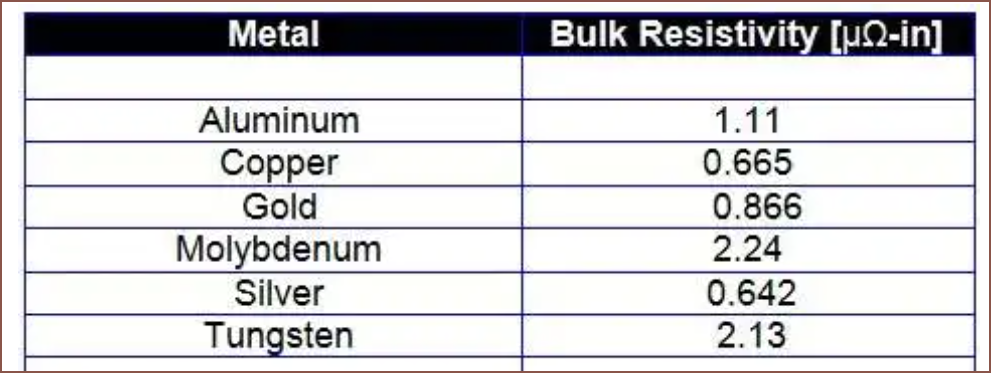
I feel like I'm coming in, looking at and swiping every additive manufacturer's tech right now. First BCN3D, then trying to replicate Stratasys' Polyjet, continuous fibre reinforcement from Desktop Metal and CF3D, Nano Dimension and now my eyes are on Voltera. As you can see, the gels are pretty distant from copper (and the other metals, seen below).
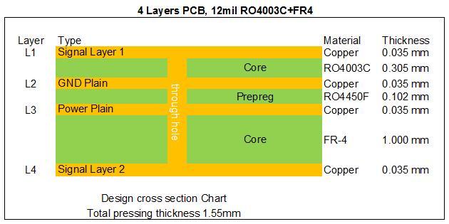
![]() For a 1.6mm, 4 layer PCB, there does seem to be enough room to make any 1oz traces (35um) into thicker ones like 80um or 160um, which should help with resistance issues.
For a 1.6mm, 4 layer PCB, there does seem to be enough room to make any 1oz traces (35um) into thicker ones like 80um or 160um, which should help with resistance issues.![4 Layer PCB Board Bulit On Rogers 12mil RO4003C and FR-4(id:10944752). Buy China RO4003C, High Frequency PCB, Digital Radio Antenn - EC21]()
.16+.28+.16+.12+.16+.28+.16 = 1.32mm
.16+.32+.16+.12+.16+.32+.16 = 1.40mm
That would leave enough for a 120um thick soldermask each side to acheive a 1.64mm PCB.
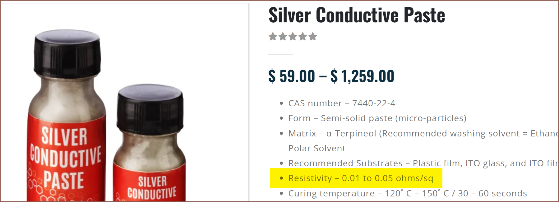
Anyway, it seems they're using "silver electrically conductive adhesive" and I was able to dig around and find something:
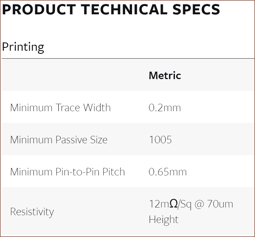
![]() While technically expensive (£7,866/L), it sounds like the stuff in the paper by the description:
While technically expensive (£7,866/L), it sounds like the stuff in the paper by the description:![]()
![]() Is it me, or is that resistance really low? Perhaps there's an extra 0?
Is it me, or is that resistance really low? Perhaps there's an extra 0?![]() Nope.
Nope.Why is the resistivity 1/6 of copper? I don't recall silver being that much better than copper in the electrical resistivity table I found a day or two ago.
[26th Aug] It's because I didn't notice that the pastes are in ohms/sq not milliohms/sq. The first paste is 20mOhm/sq and the second is 10-50.
Liquid Laminate Lithography 3D Printer [gd0105]
The best of resin with the best of filament; is such a 3D printer possible?
 kelvinA
 I accedentally forgot the X axis linear rails and to make sure that the spreadsheet calculated the extra 2 roller rails, so the difference in price between the 204.8*163.6*170mm and 307.2*163.6*230mm is only expected to be a sub £10 difference: £6 for the longer bed and pennies for the longer leadscrews and linear rails.
 I've added in a few components, such as SuspenseSmall exclusives and new things like the 10 contact image sensors. Oh right I haven't mentioned it in the previous log, but I'm thinking that there would be a real benefit on debug/testing and features (explained below). I've also seperated the quantities into Suspense and SuspenseSmall so that it's possible to track an estimate to either. The Small will likely cost more if components were sourced by themselves.
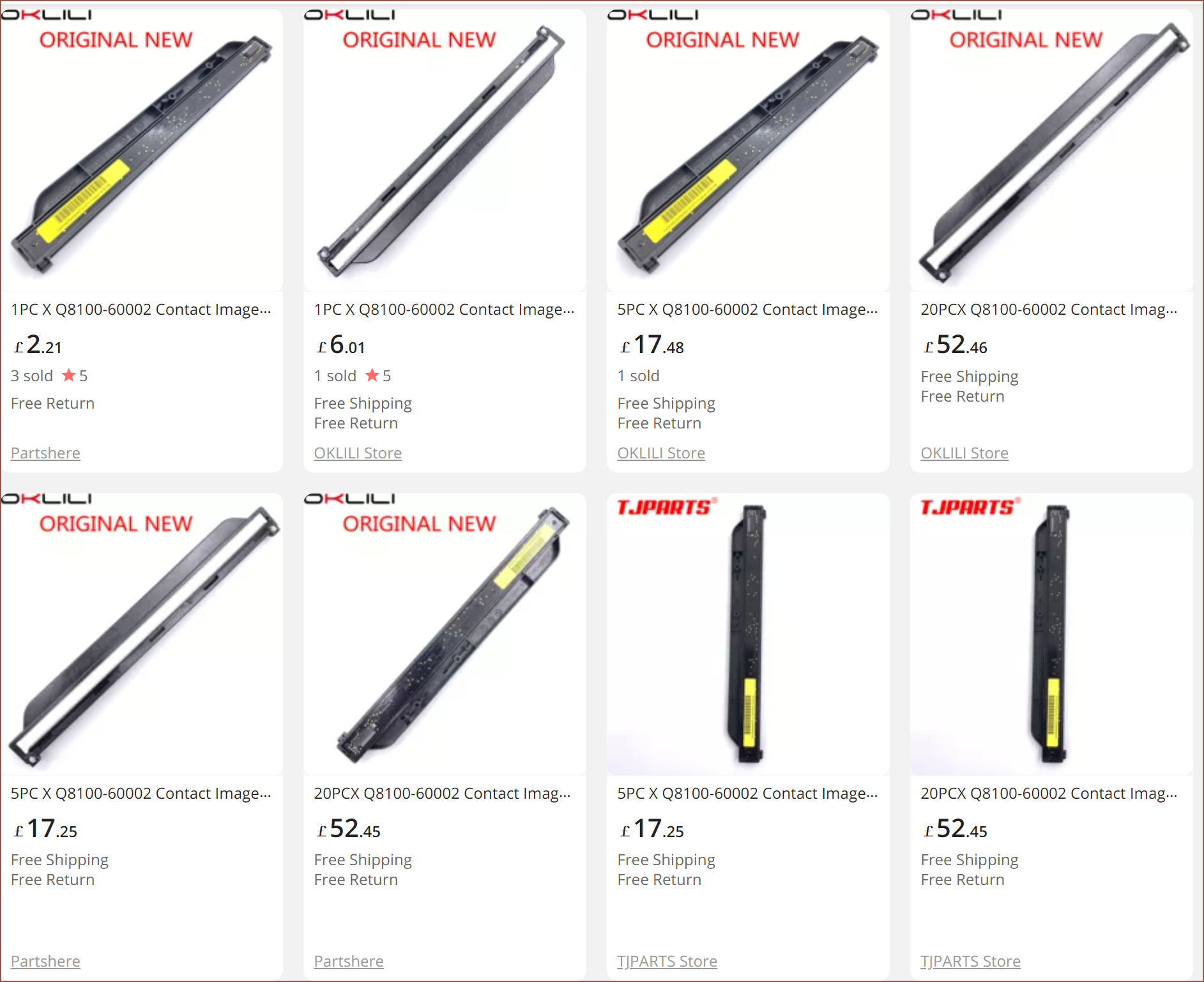 I've looked into some of the printers listed and they all seem to be over a decade old, so I'm suprised that there's still so much part stock today.
 By moving the roller down 10mm, I've been able to move things around so that the small bed assembly is 348.5mm wide. Z height for the Small is 175mm.
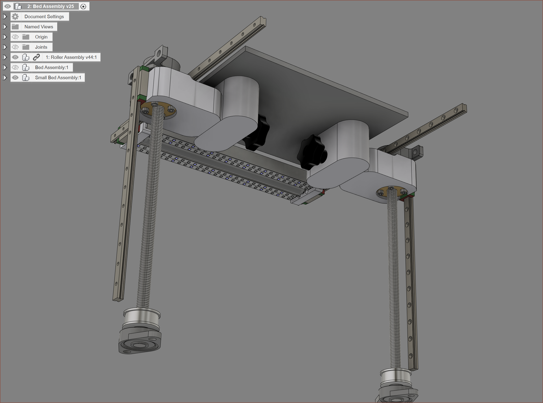 As you can see, I've redesigned the Z assembly to use the T12 leadscrews instead of the ballscrews. 5M 20T pulleys are used because they're cheaper than 3M from the AliExpress seller I found for some unknown reason. For bed alignment, I'm opting for 2-point 1 rotation levelling. There should be 1cm of clearance to remove the M8 star bolts.
  This is for a SecSavr SuspenseSmall with the following specifications:
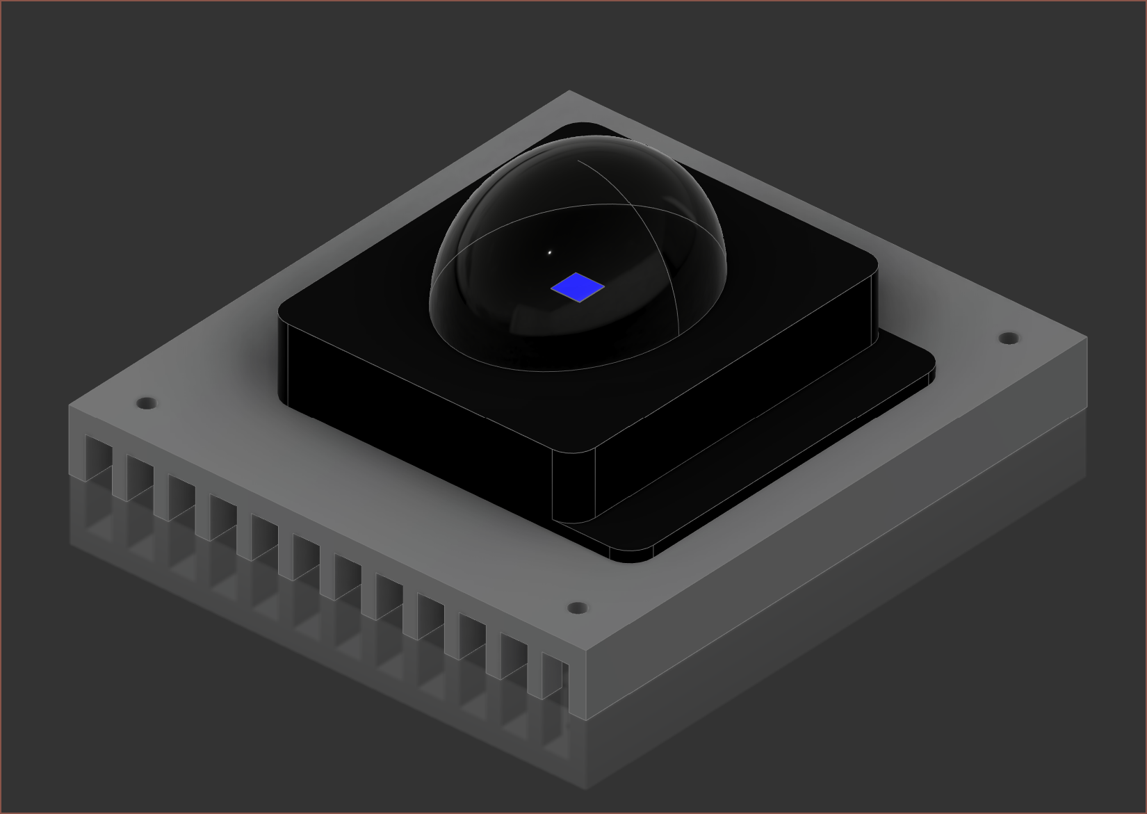 The heatsink is the most important, with these dimensions provided by the seller:
 I more or less "eyeball-ed" all the other components, and the height comes to 46mm, so I belive I'm close.
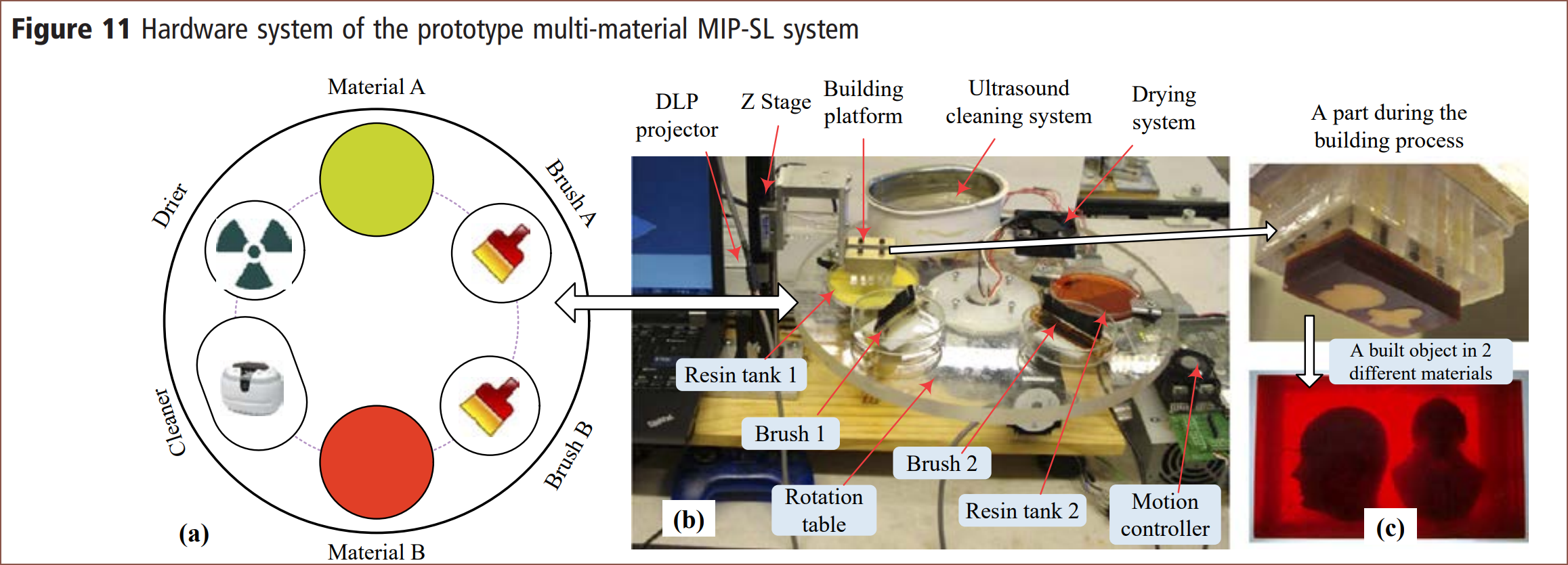 They used shallow vats that needed a minimum of 0.5mm of resin due to surface tension. I'm targetting for as low as 0.05mm. Hopefully, that would eliminate the need of the second cleaning step in their 2 step process:
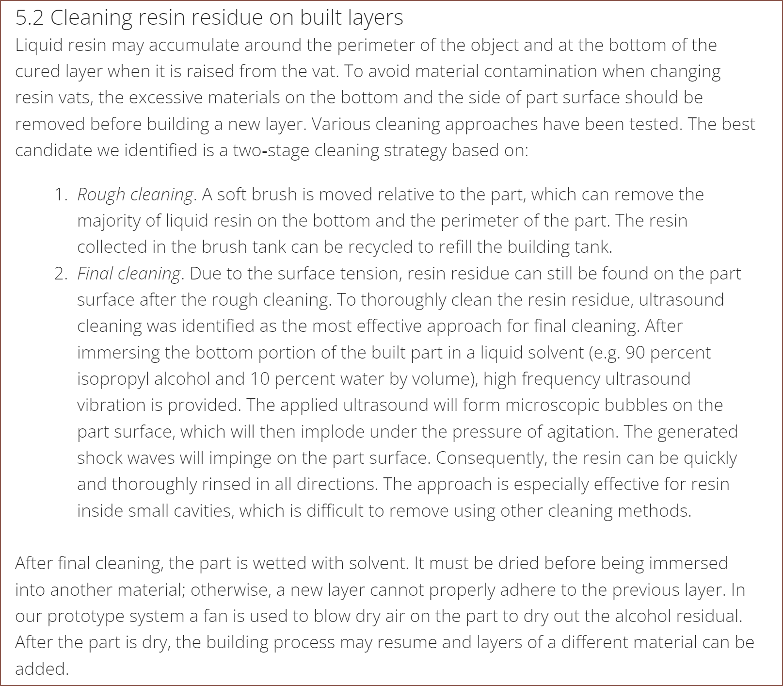 I'm not using a brush because I don't think that they could be cleaned over the course of an average print job. I'd like to avoid solvents due to VOCs and because of the drying requirement that they also mentioned. The vacuum from their more recent work could be an option, but they're loud and I have a 510mm span to cover. An option could be to move across the X axis, reducing the span to 168mm, but then there's the uncured resin cleaning job inside the vacuum gear to contest with, which I'd imagine would be more complex than curing a saturated thread. Speaking of the thread, I have thought about wiping the part with it directly, but I worry about consumable consumption and the thread getting caught on the print.
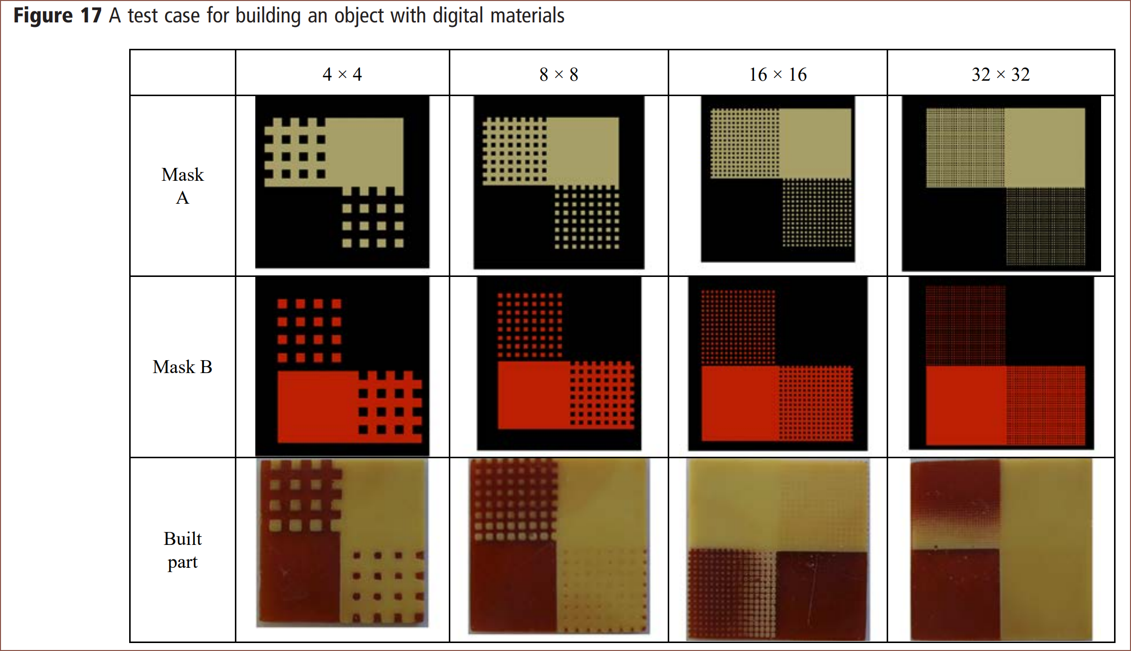 Perhaps the reason is due to this note they made in their conclusion:
 The potential for air cavities is the reason why I hypothesise that the smallest "colour island" would be 80um+ instead of 40um.
 For their vacuum system, they surely get closer to BCN3D's "every single drop will make it to the print" (pharaphrased) ideal.
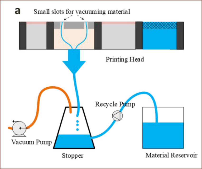 I have my concerns that a relatively high viscosity resin would be sucked into the vacuum, and the researchers used a speed of 3mm/s which is not going to work.
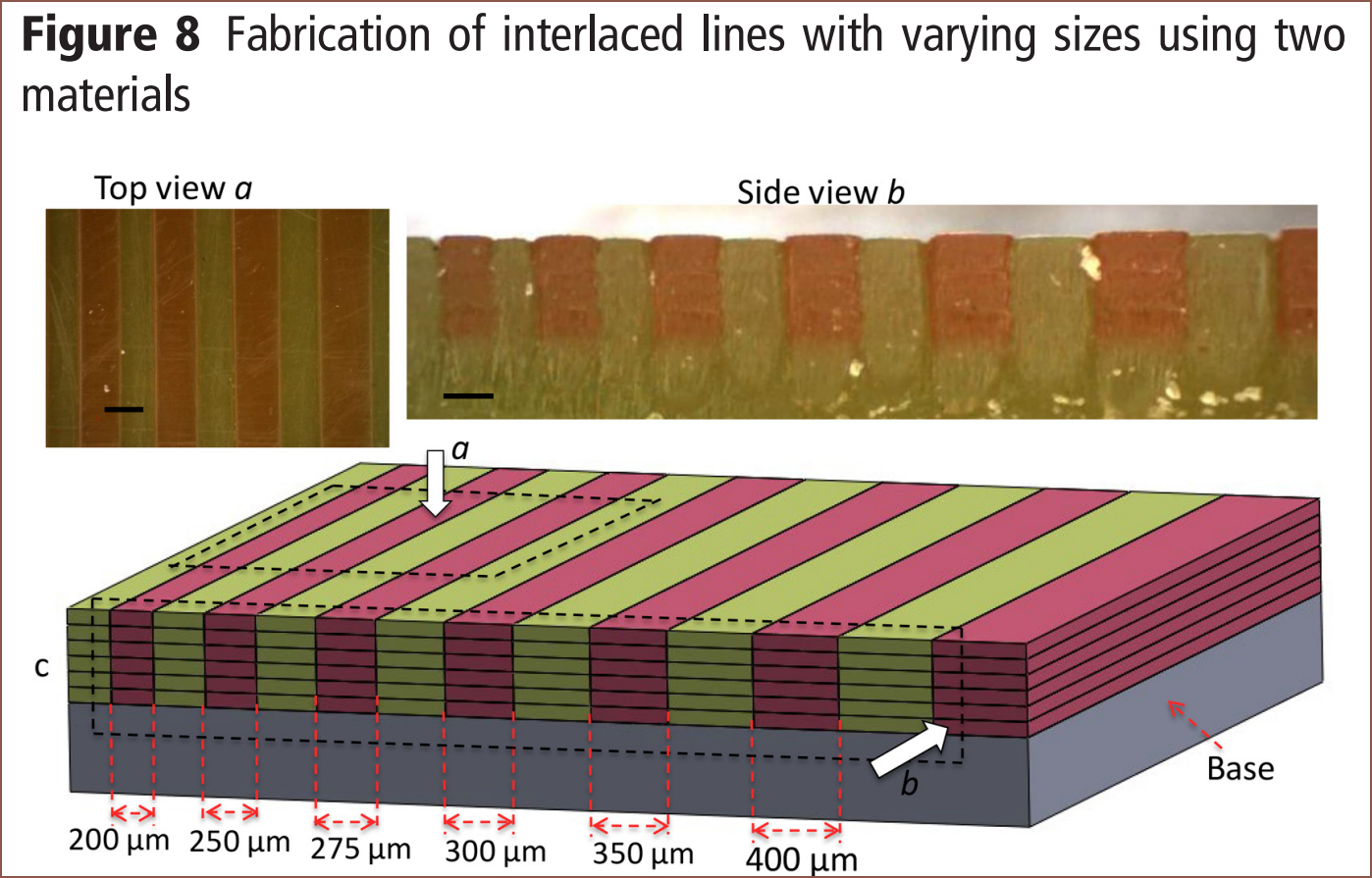
 Figure 10 looks especially promising.
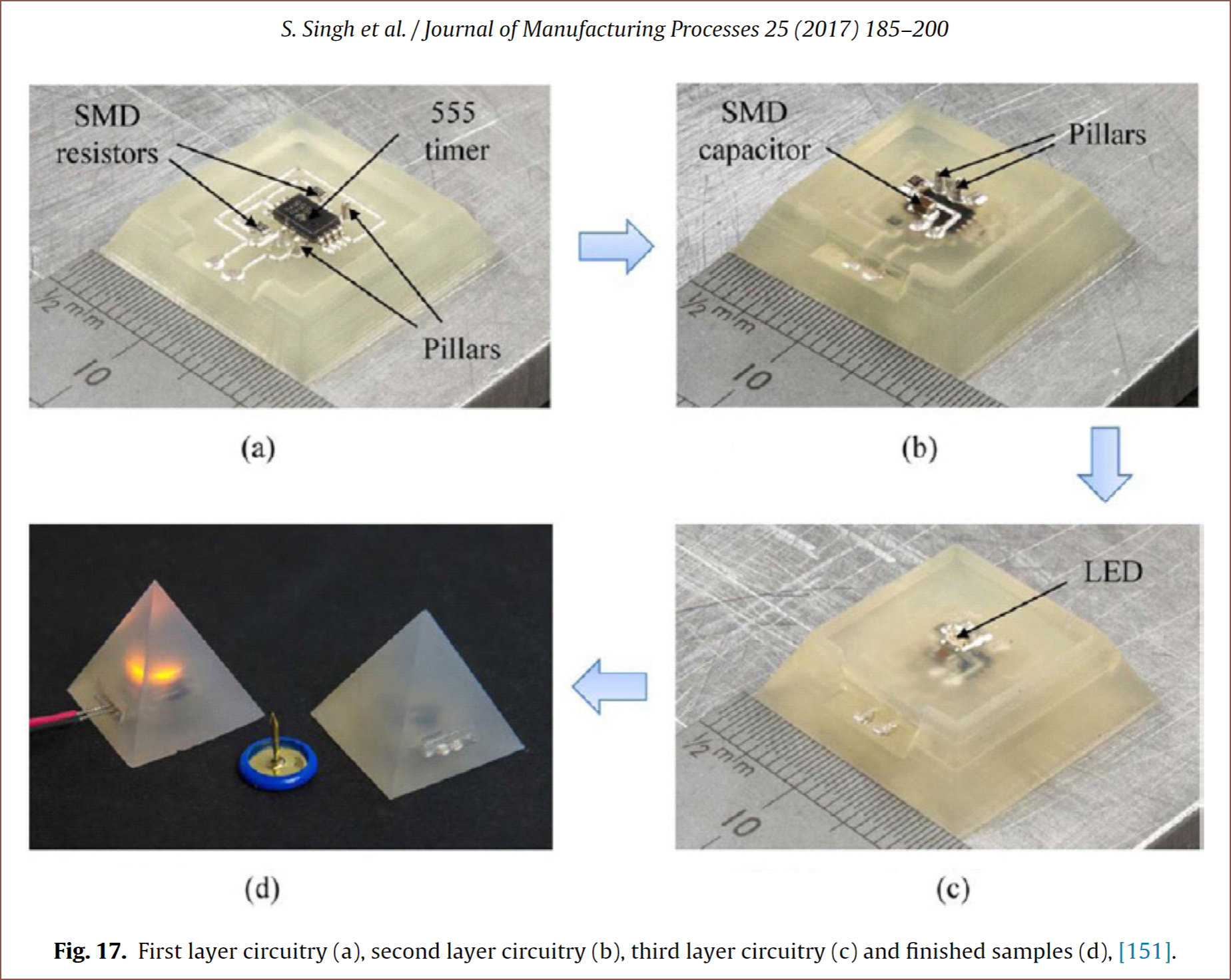 So I looked into this paper and the method they used, which is seen below:
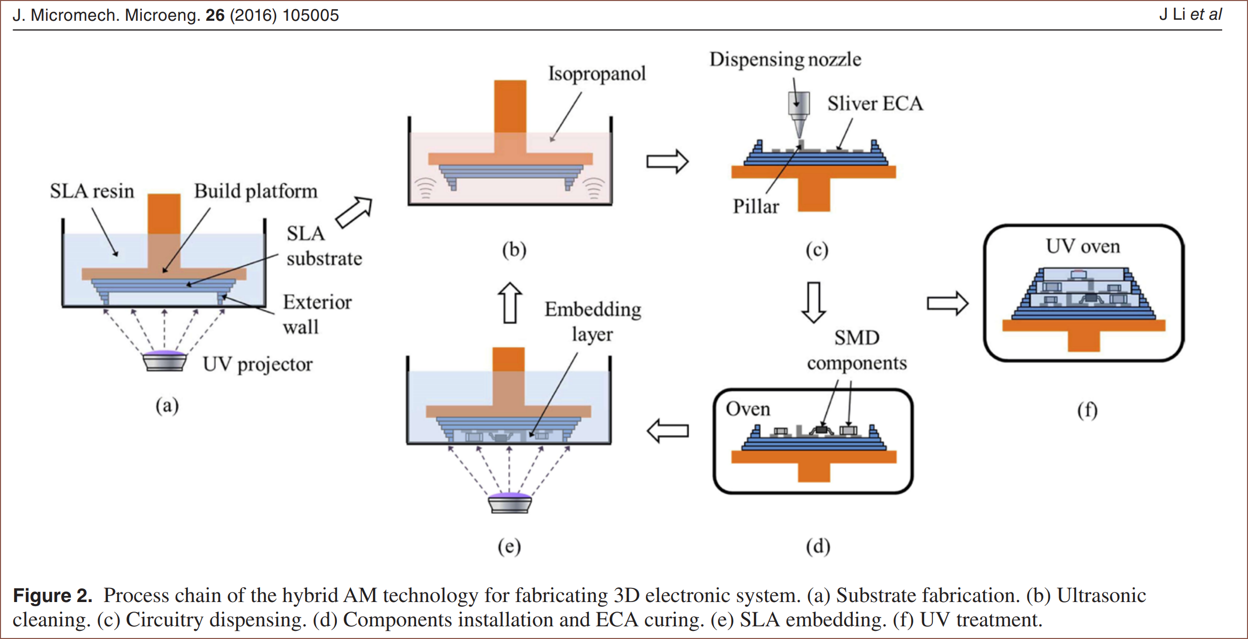 I had a feeling that some kind of dispensing paste was more likely to happen than a decently conductive UV curable resin. If the cleaning roller works as intended, I'd likely be able to have a more streamlined process to what these researchers acheived in 2016. I doubt I'd have to use the oven until the part is finished since they won't be upside down or pushed around by resin in a vat. They use a clear resin with a Tg of 100C.
  I've highlighted 70um because that is the same thickness
 For a 1.6mm, 4 layer PCB, there does seem to be enough room to make any 1oz traces (35um) into thicker ones like 80um or 160um, which should help with resistance issues.
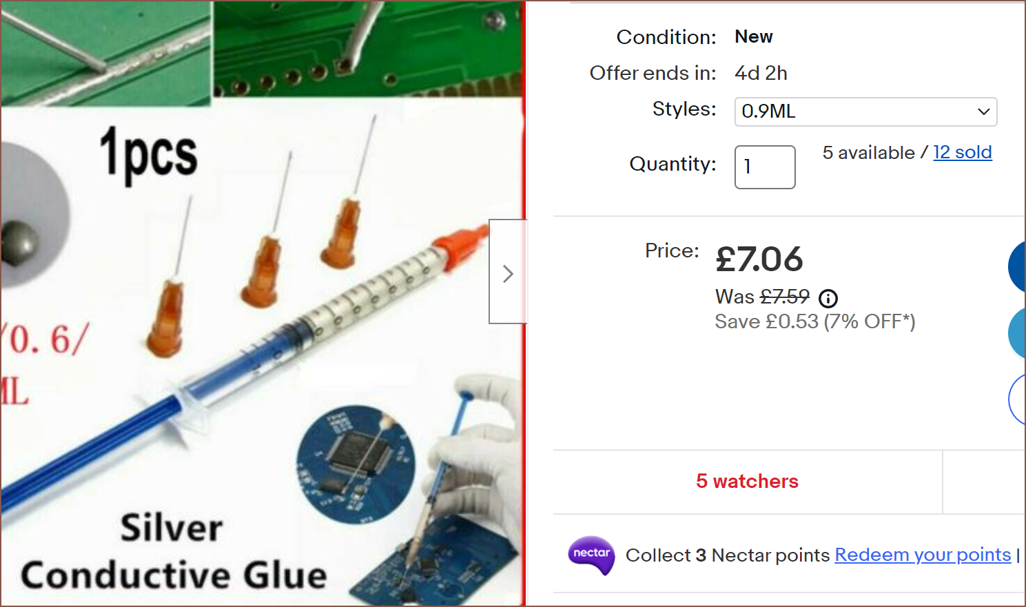 While technically expensive (£7,866/L), it sounds like the stuff in the paper by the description:
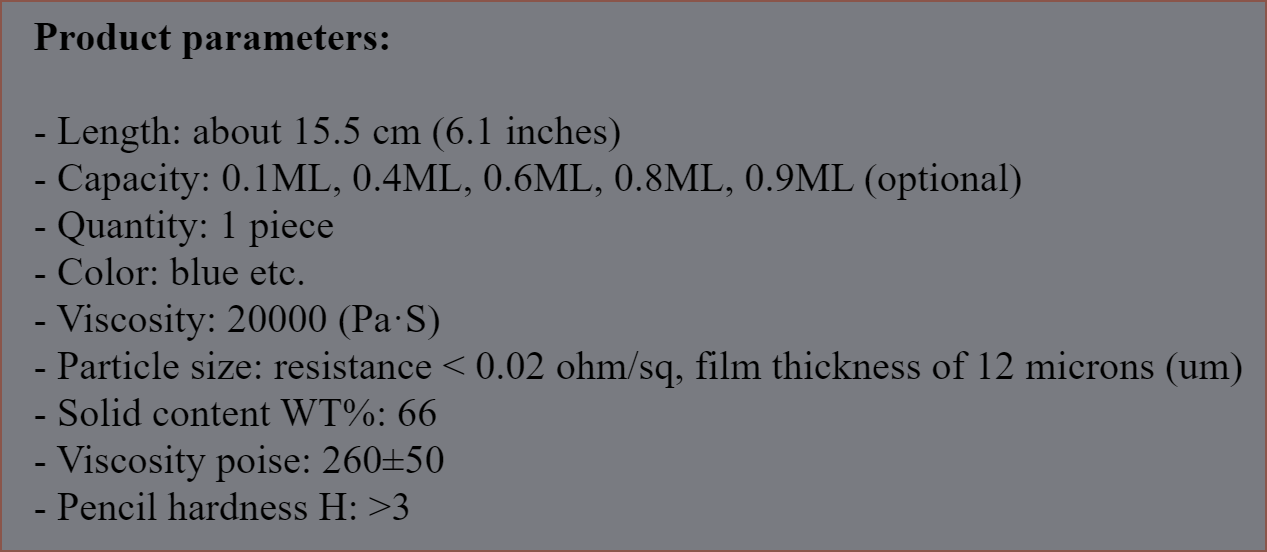
 Is it me, or is that resistance really low? Perhaps there's an extra 0?