-
Assembled the Enclosure
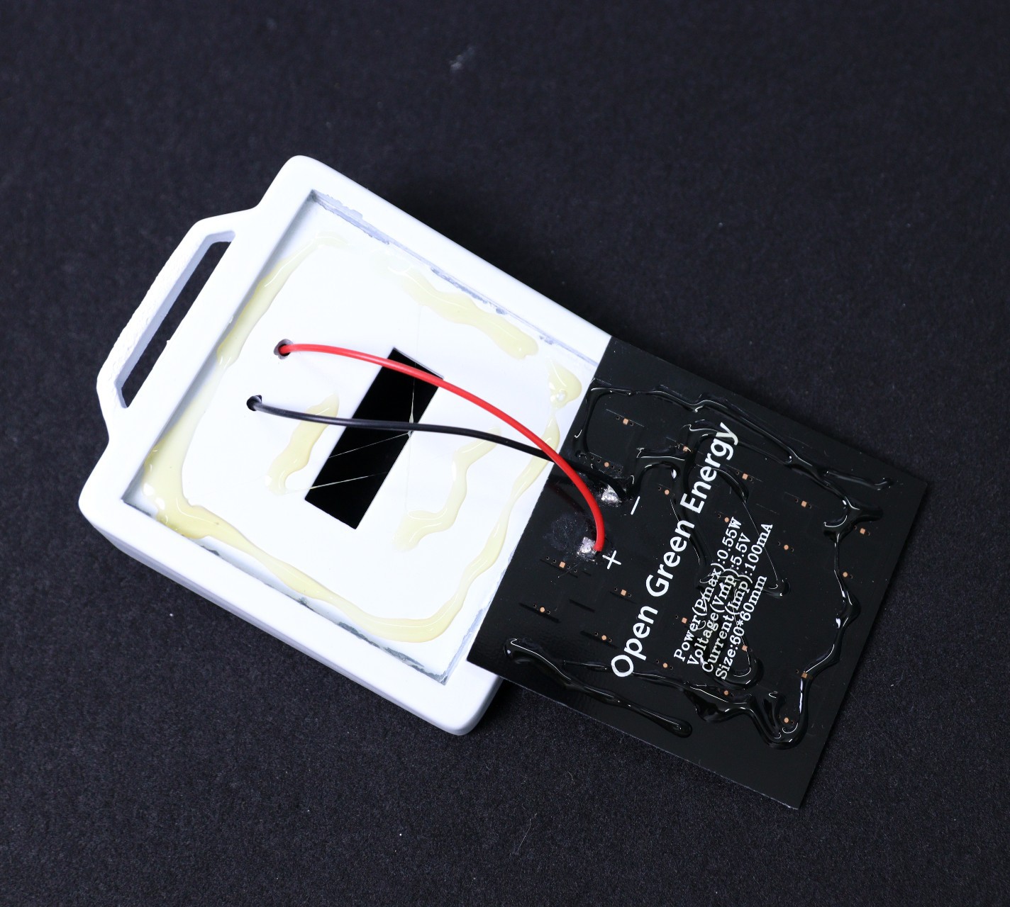
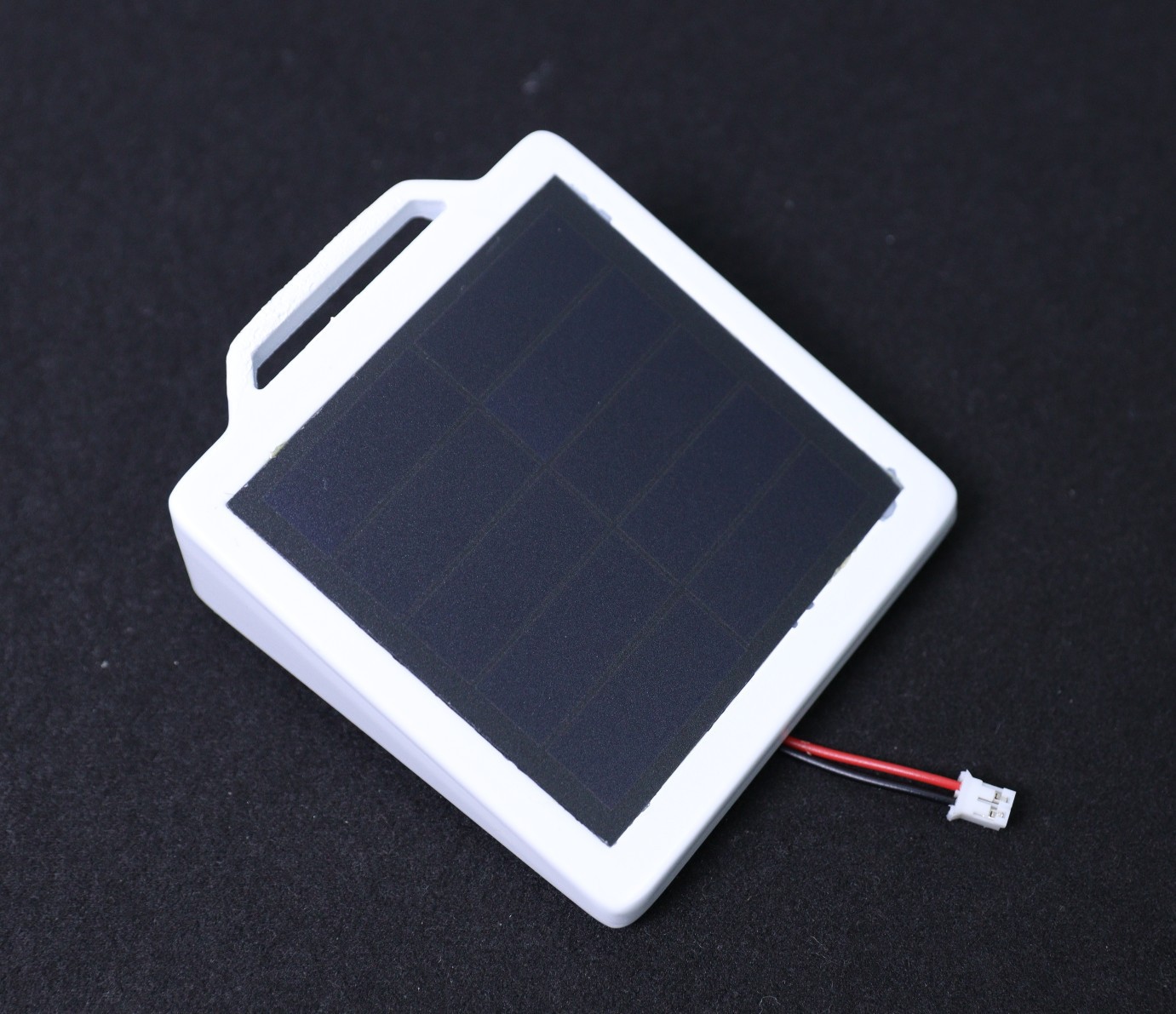
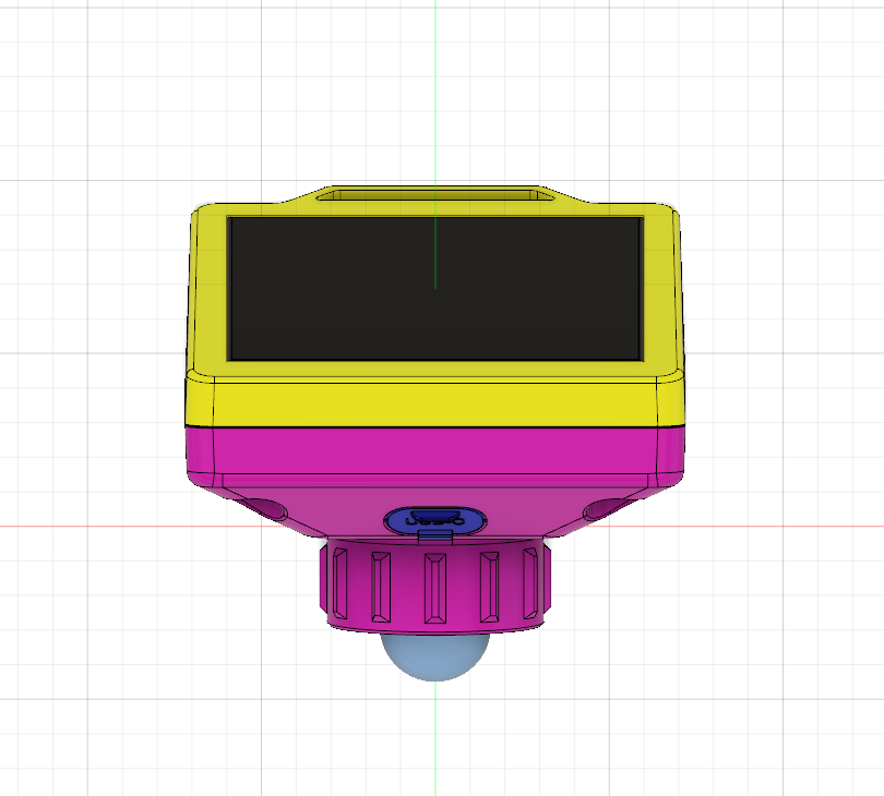
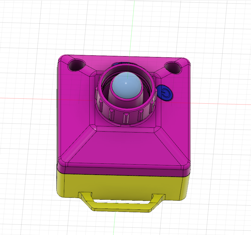
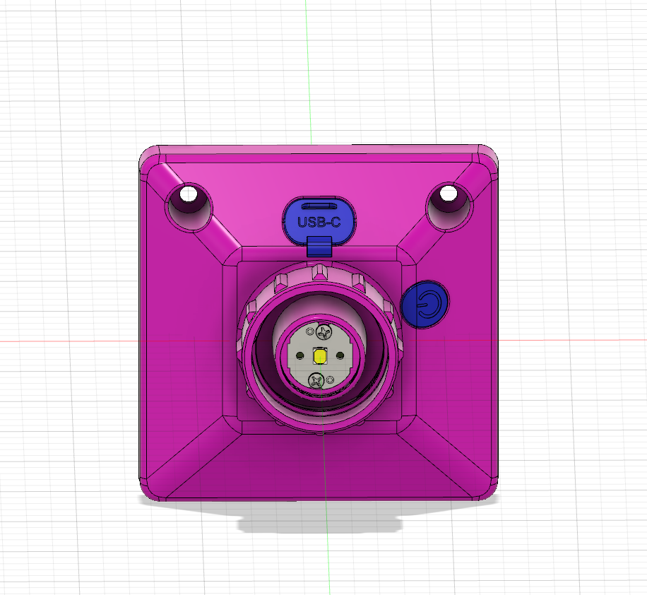
10/24/2022 at 02:00 • 0 commentsAfter testing the Circuit, I have assembled the enclosure. The assembling process is as follows:
1. Install the Solar panel on the top part of the enclosure.
![]()
![]()
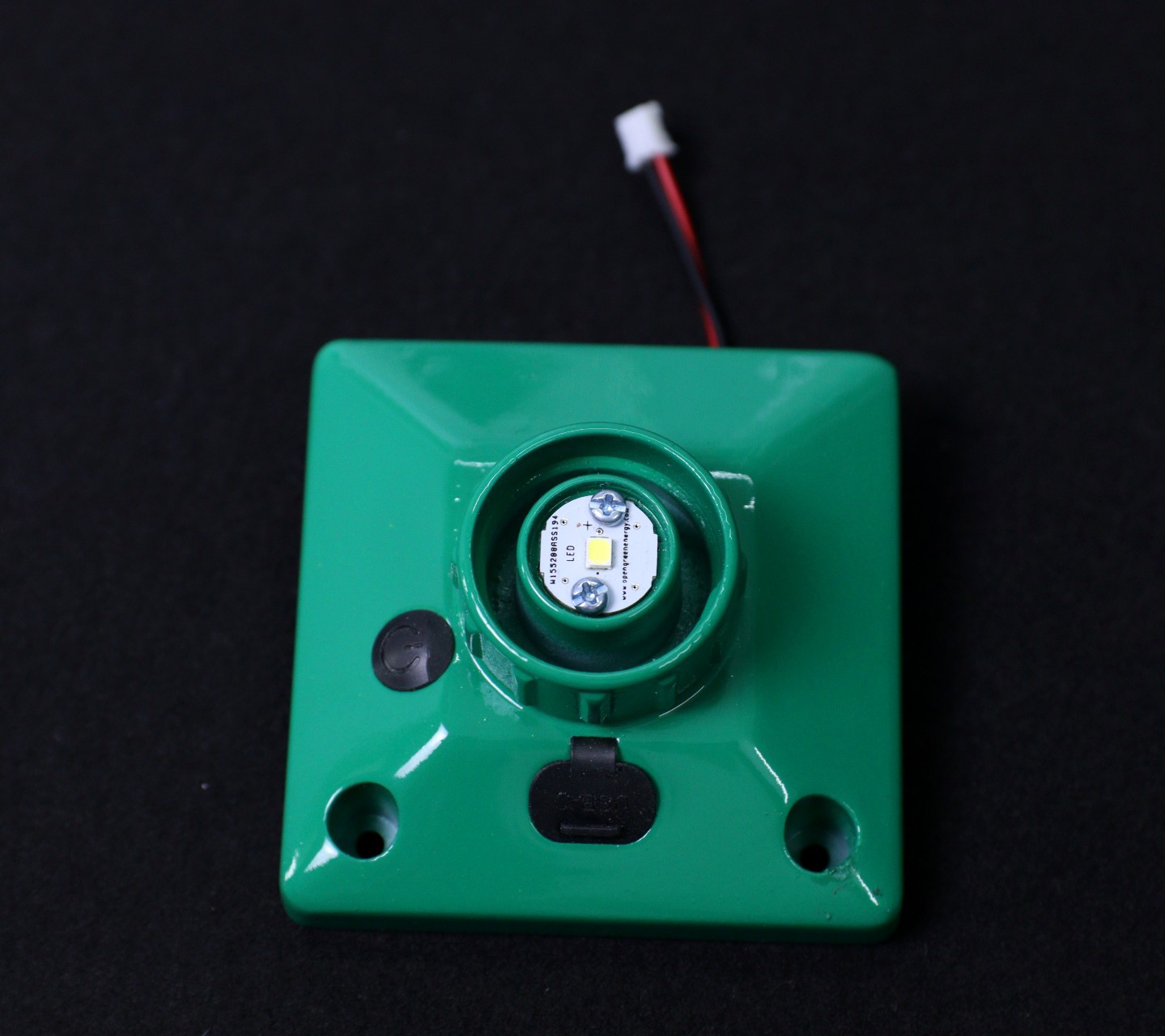
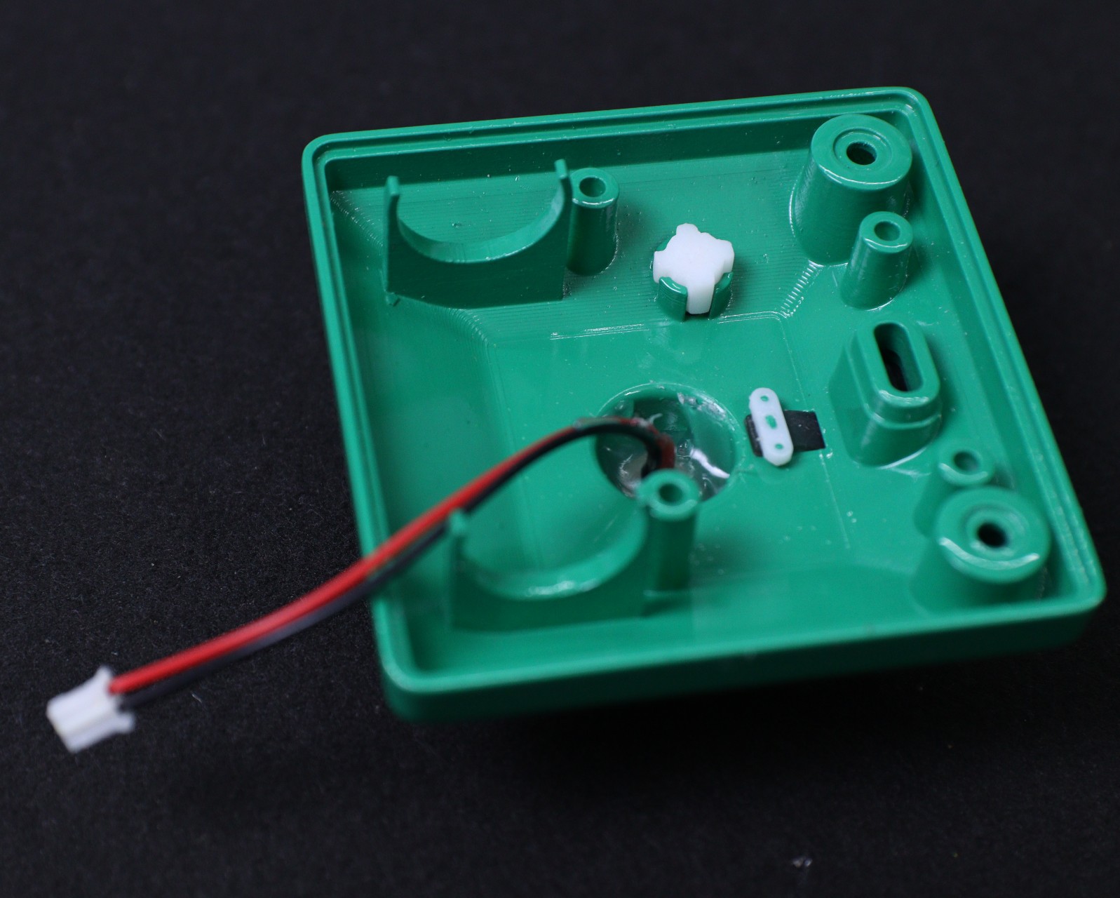
2. Install the LED PCB and seal it from the inside to prevent water ingress
![]()
3. Install the Button Switch Cap
![]()
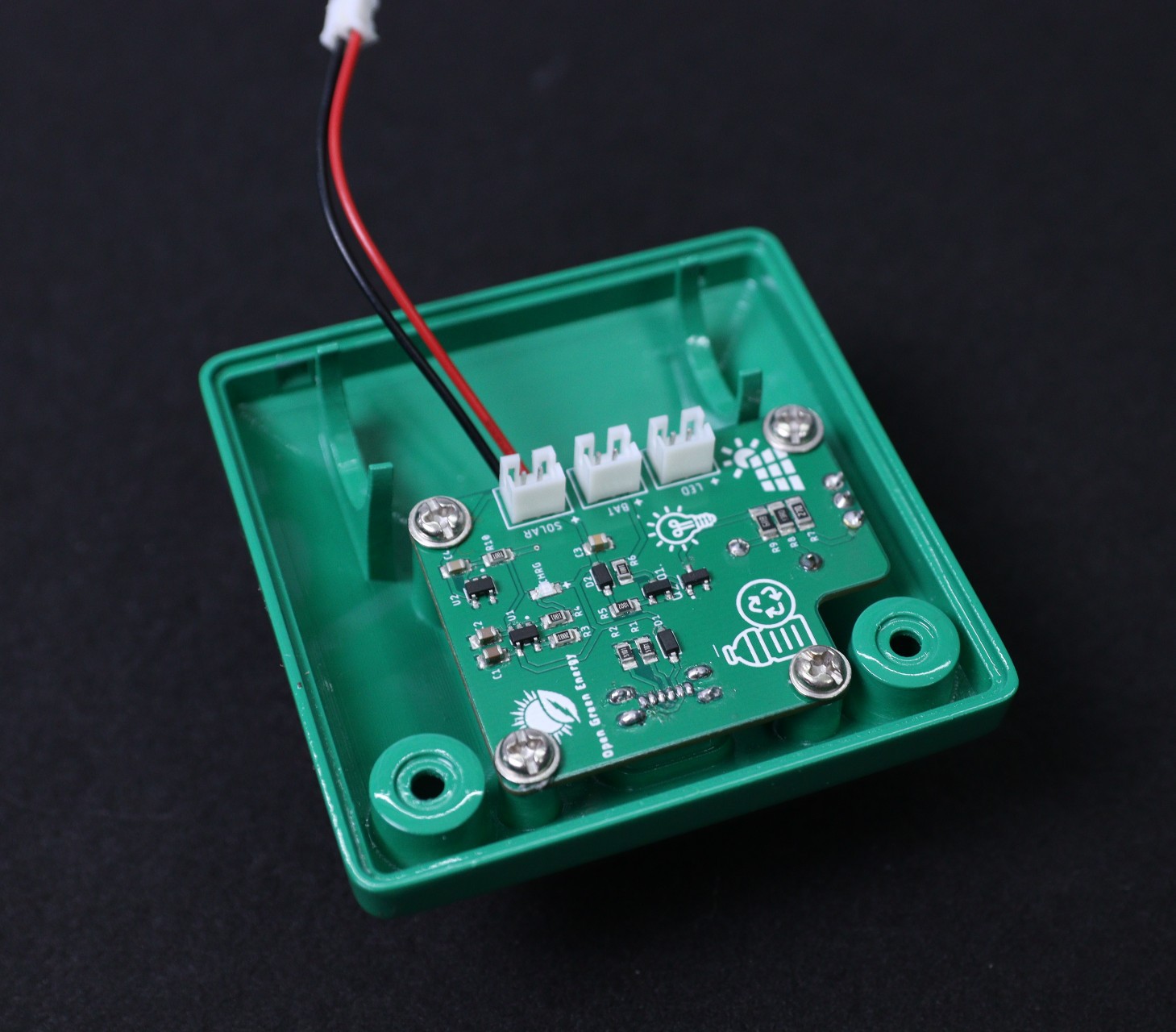
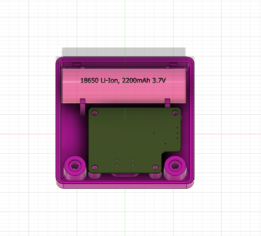
4. Install the PCB board and secure the 4 screws at the corners
![]()
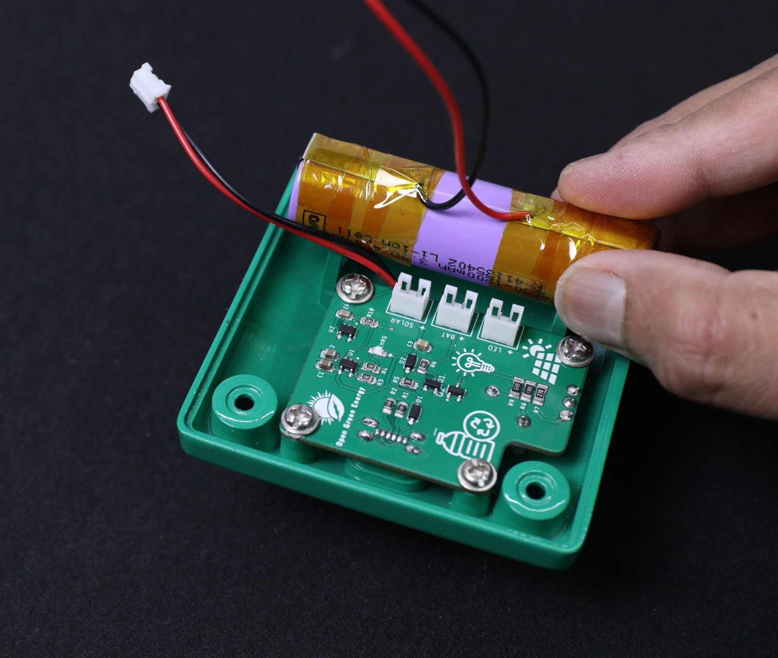
5. Install the 18650 Battery Pack
![]()
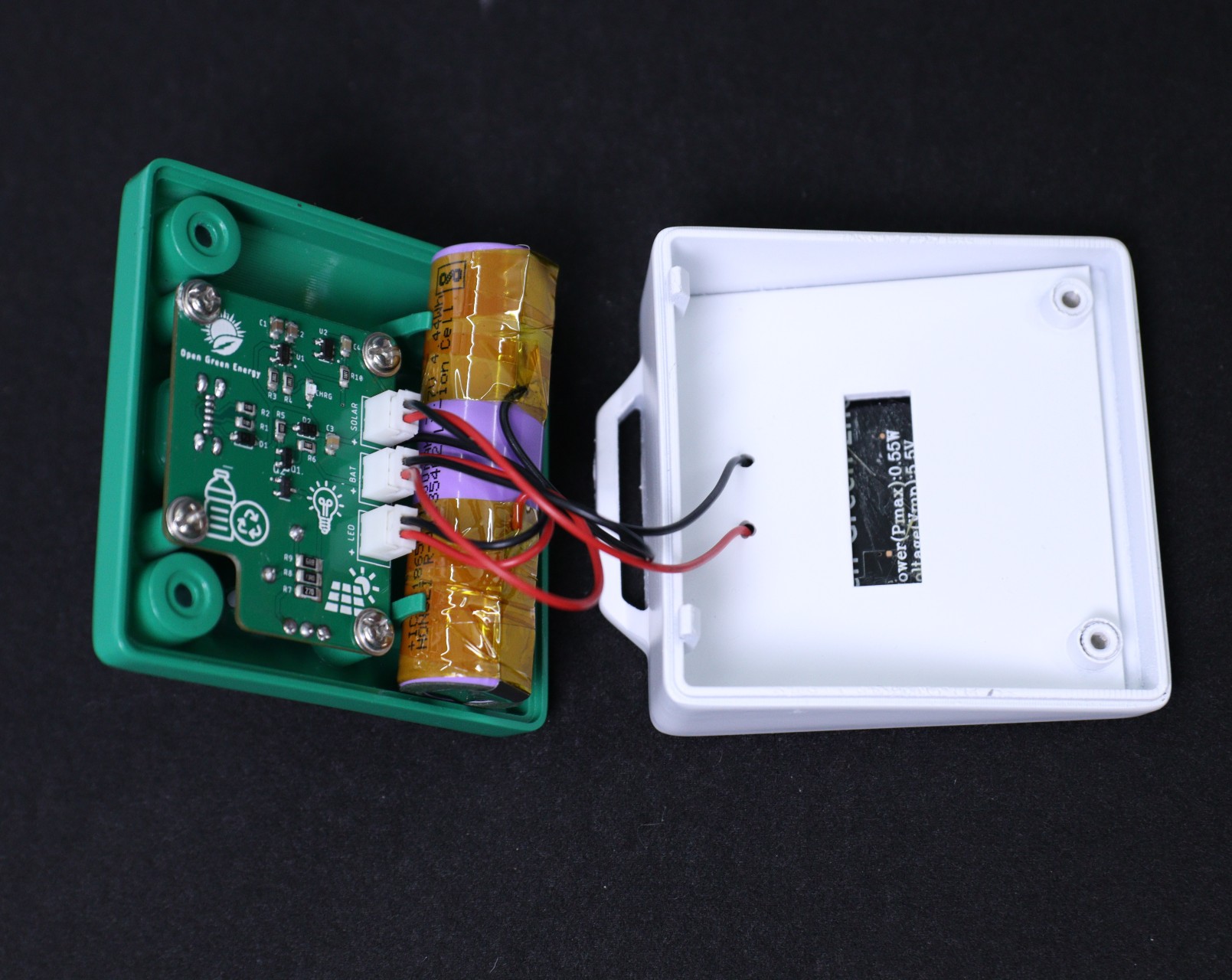
6. Connect the LED, Battery, and Solar panel connectors to the PCB board. The labels are indicated on PCB with a polarity symbol.
![]()
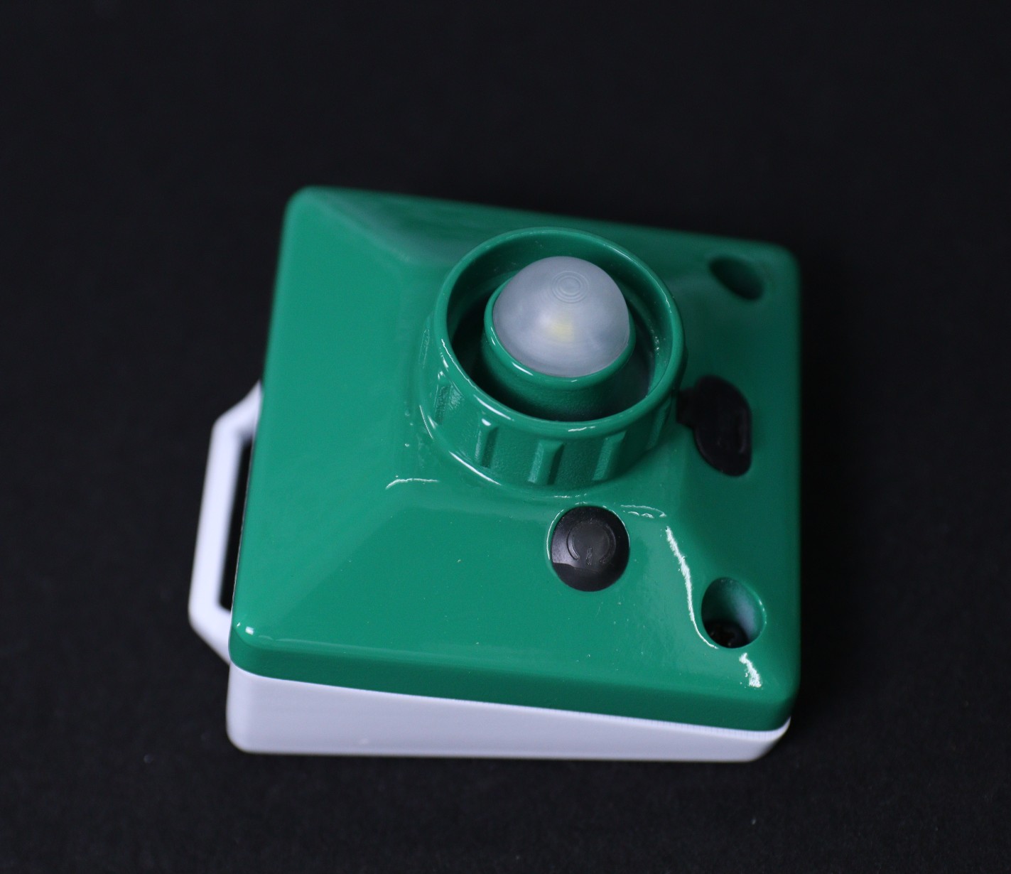
7, Align the top and bottom parts and close them by using two screws. Finally, install LED diffuser.
![]()
-
Tested the Circuit
10/24/2022 at 01:39 • 0 comments![]()
![]()
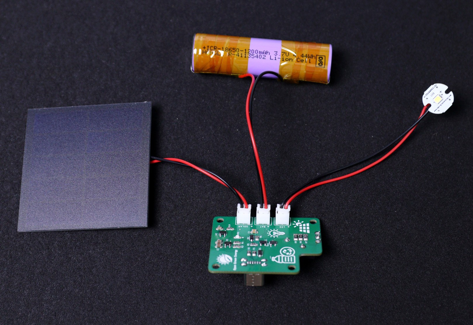
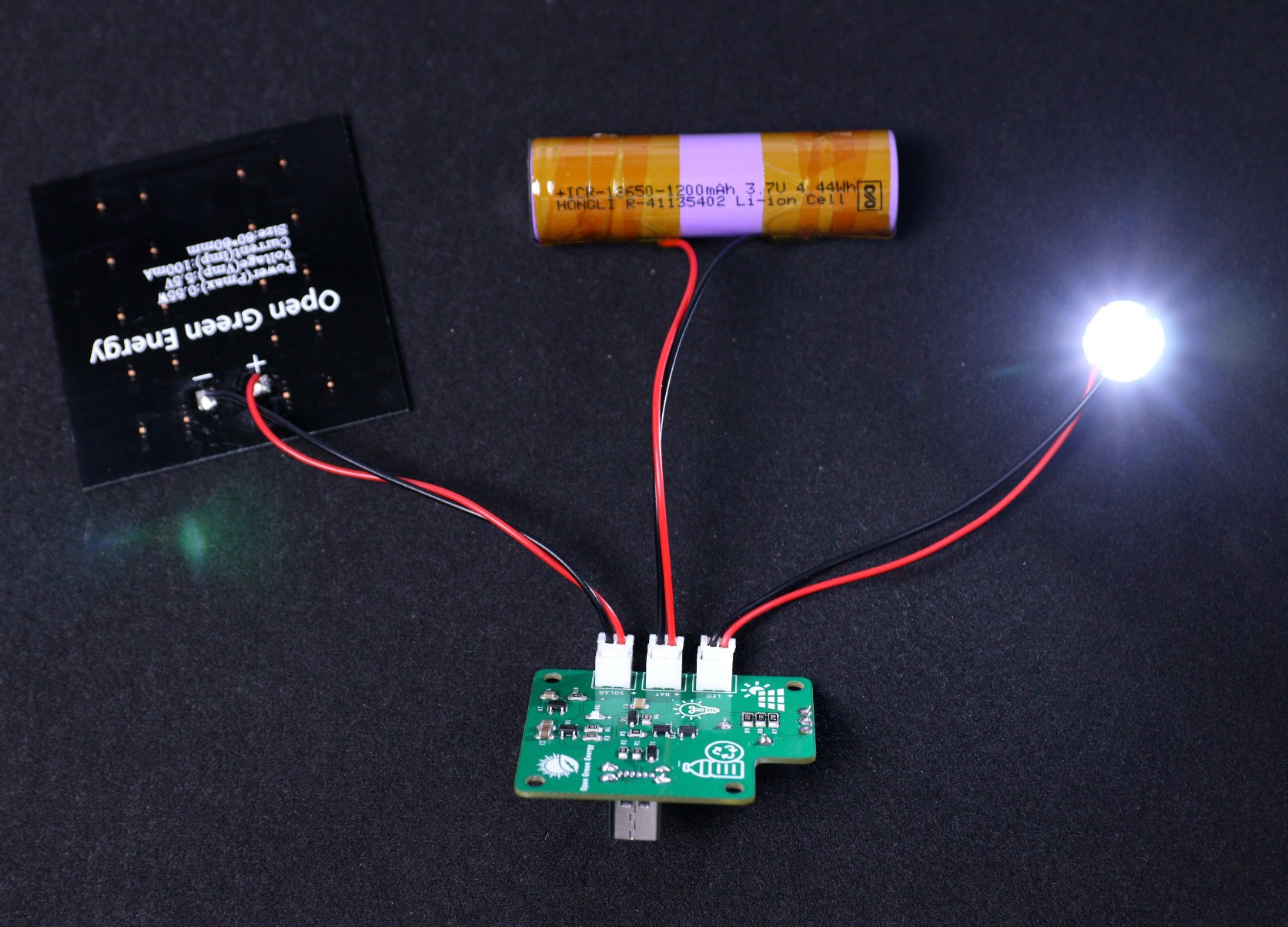
I have tested the circuit as per the above setup. The PCB is working as expected. I have also tested the backup time and the following are the actual results
1. Mode-1: LOW Brightness - 26 Hrs
2. Mode-2: MEDIUM Brightness - 12 Hrs
3. Mode-1: HIGH Brightness - 7 Hrs
-
Assembled the PCB
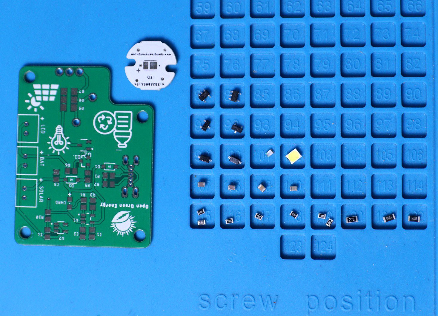
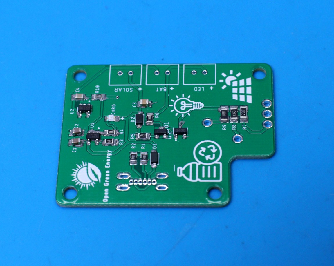
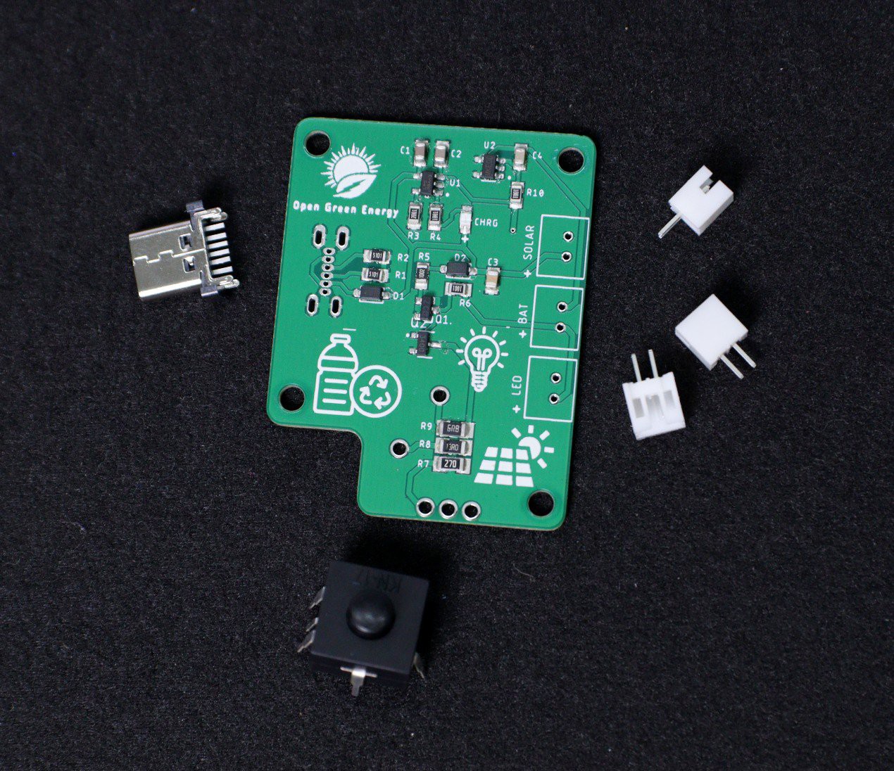
10/24/2022 at 01:37 • 0 commentsArranged the SMD components as per the schematic diagram, so that it will be easier for placing the components on the PCB.
![]()
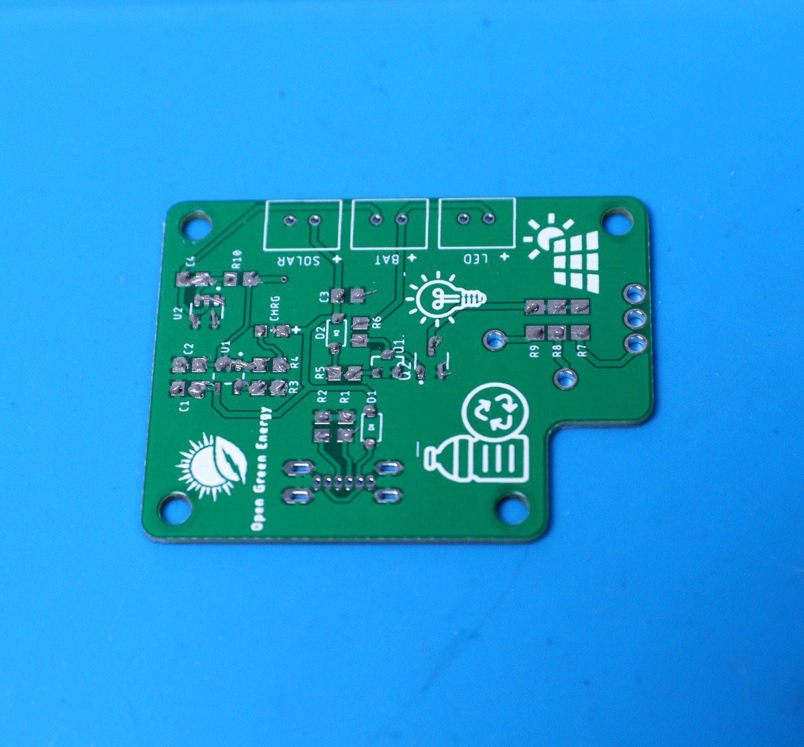
First I have applied the solder paste by using a solder paste syringe.
![]()
Placed the components by using tweezers
![]()
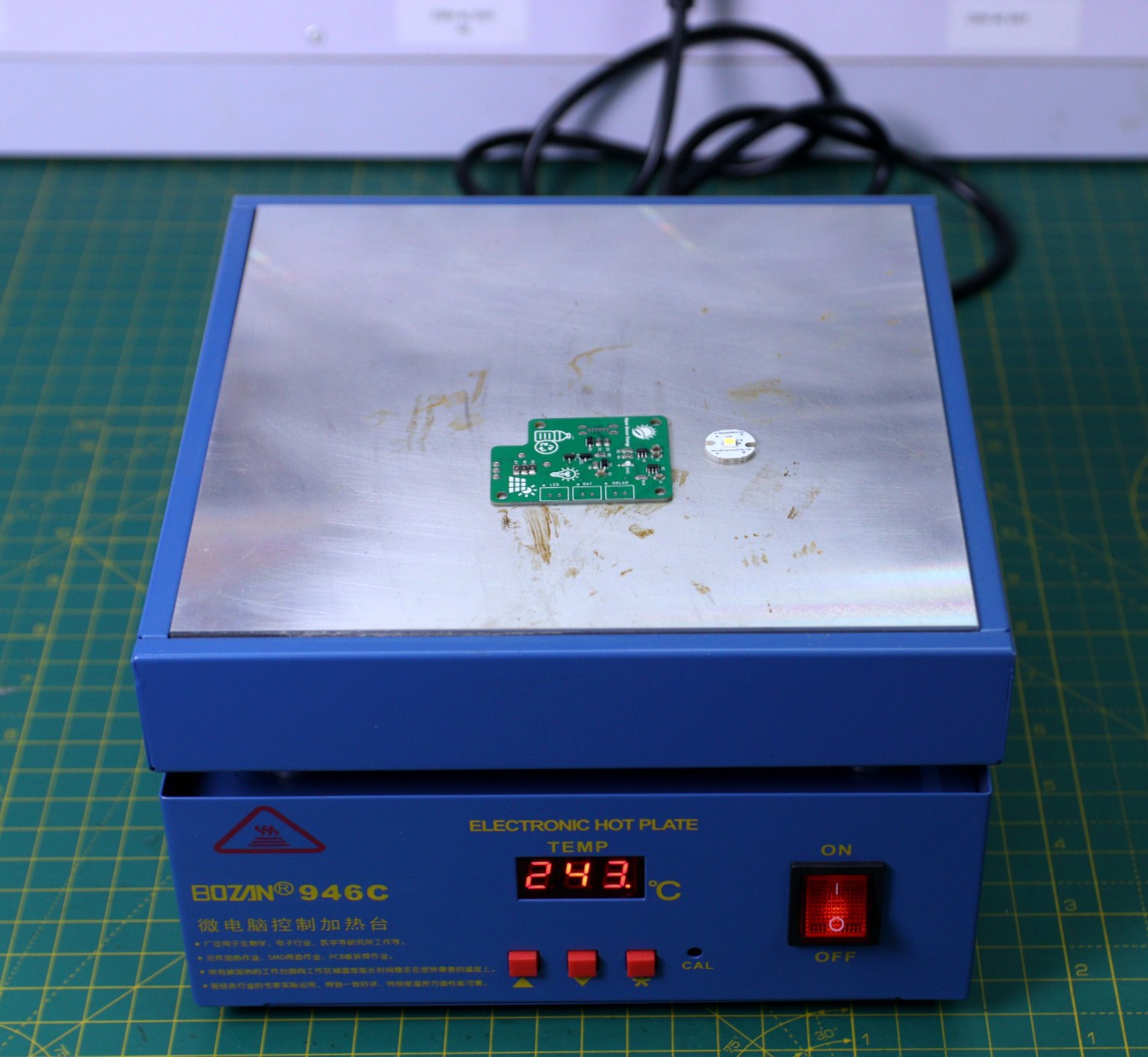
Cooked the PCB using my Hot Plate.
![]()
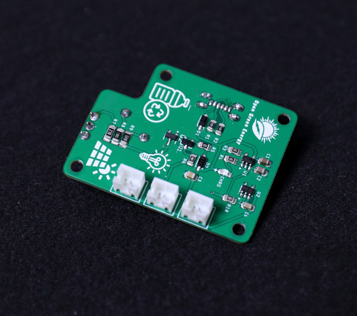
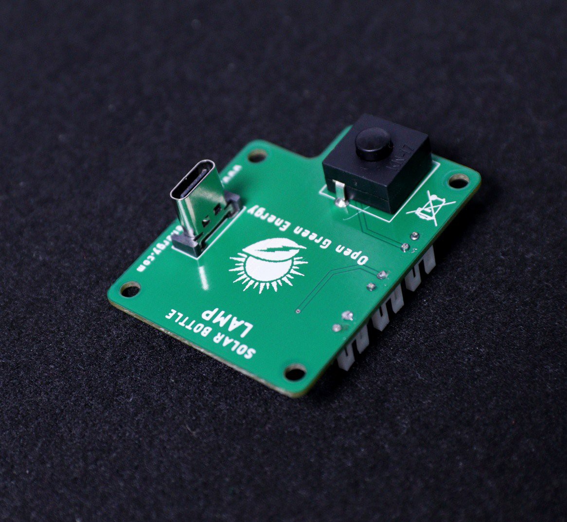
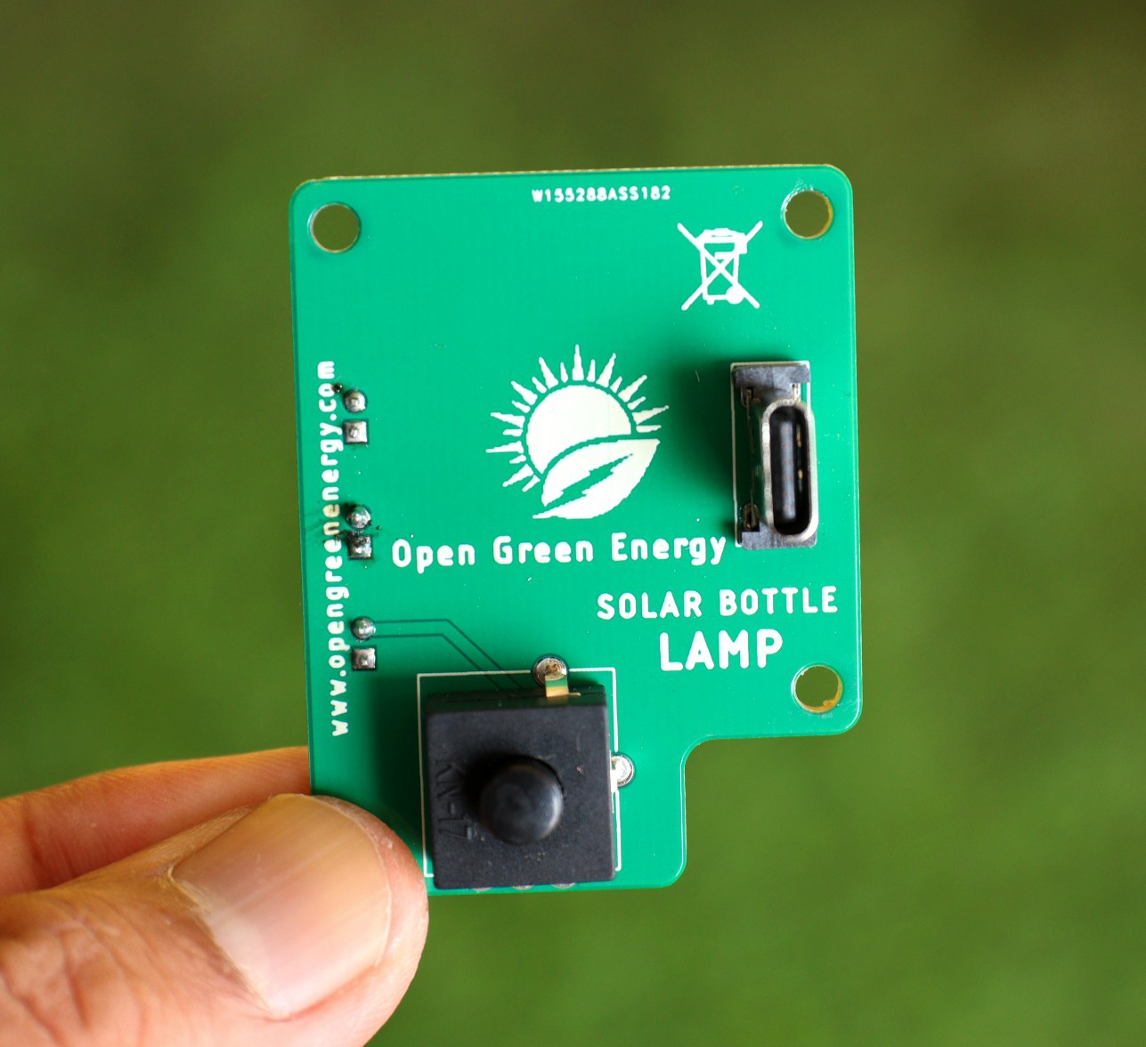
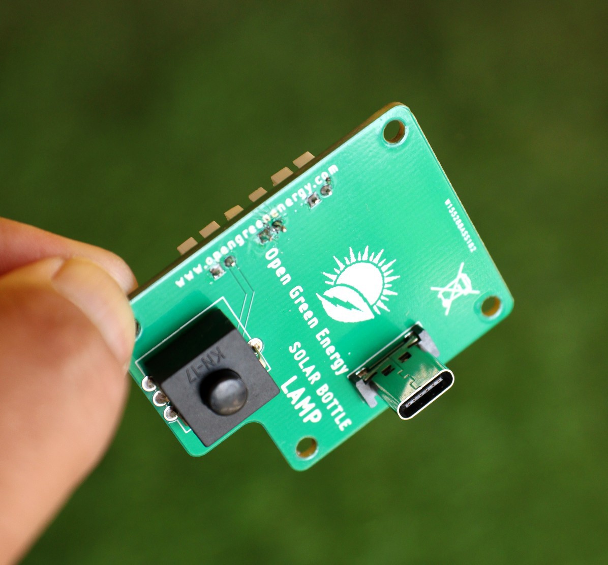
Soldered the Through Hole Components : 3 x JST connectors, Push Button Switch, and USB-C Socket
![]()
![]()
![]()
-
Enclosure Printed in SLA 3D Printer
09/25/2022 at 10:48 • 0 commentsIn my earlier project log, I shared the latest design for the Solar Bottle Lamp. Initially, I thought to print the design with my own 3D printer, but later I realized that I will never get a realistic commercial-grade product look if I print the parts with my own printer. Meanwhile, I got access to a nearby SLA printing shop and finally, I printed 3 prototypes.
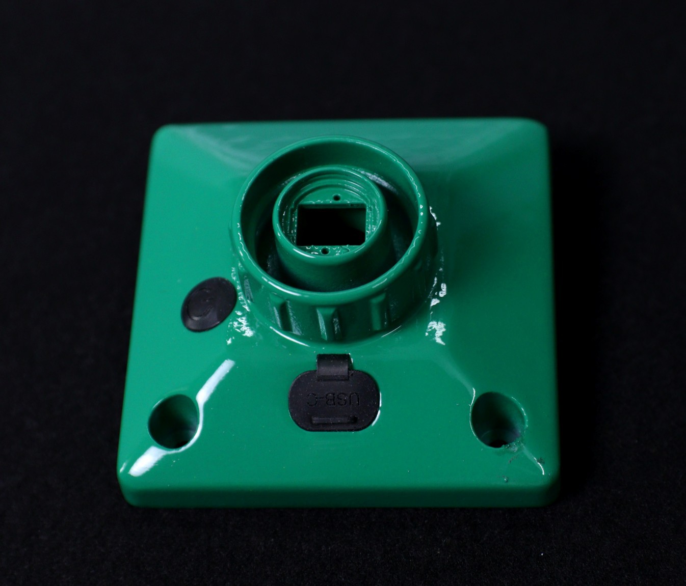
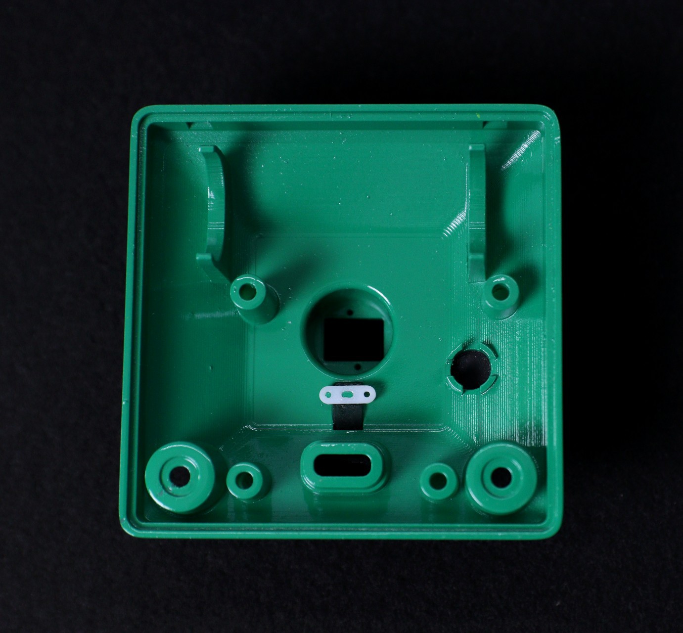
The outcome of the SLA printed parts is super smooth which is far better than my conventional FDM printer parts. I have printed the parts with white color material and then, spraypaint them with green and white color. You can see the final outcome of the different parts.
Bottom Cover:
![]()
![]()
Top Cover:
![]()
Making Semi-Transparent Parts:
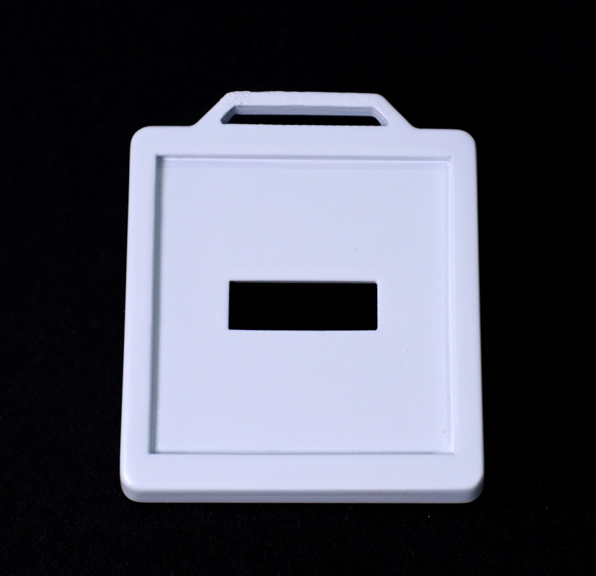
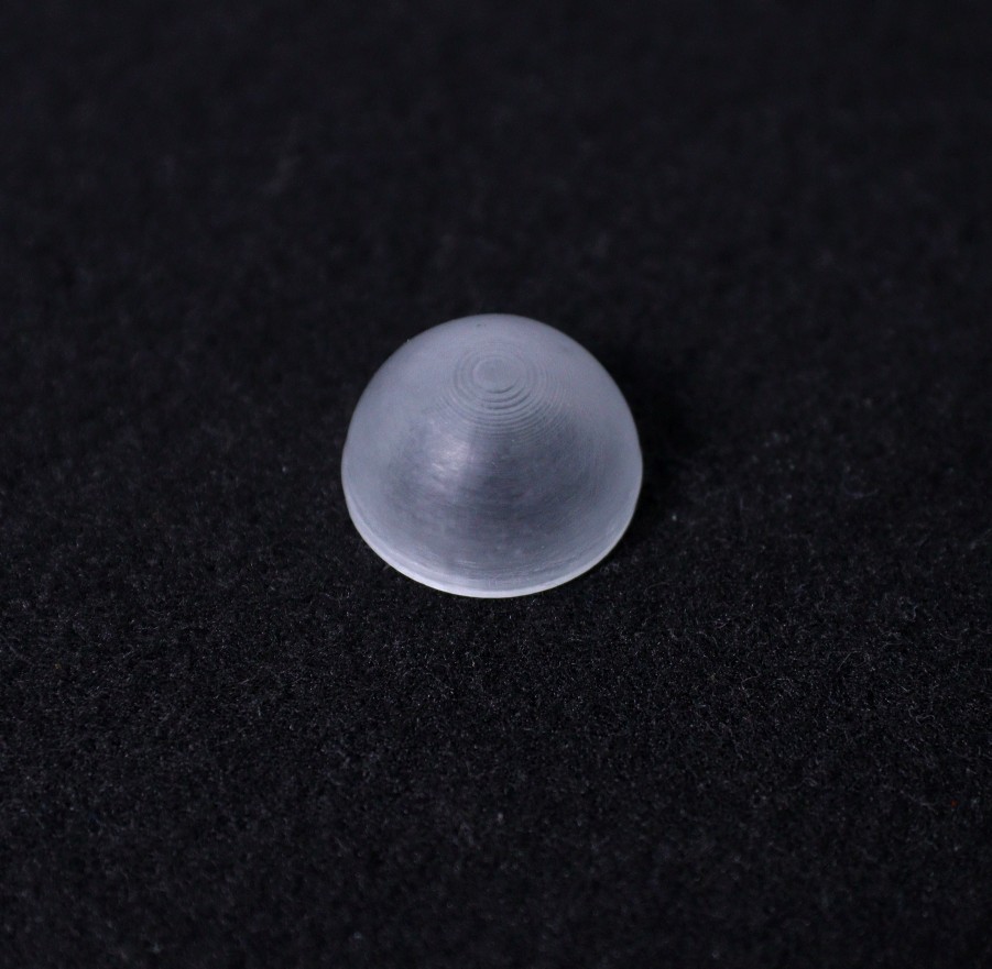
The surface is sanded using fine sandpaper, then polished with a polishing compound. This results in the clearest surface possible but it is very time-consuming and only possible on surfaces that can be sanded easily. The LED diffuser needs a lot of sanding to get the semi-transparent look, you can see the below picture.
Diffuser:
![]()
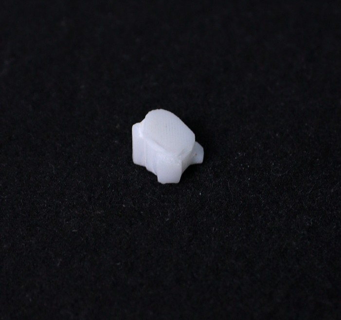
Button Cap:
![]()
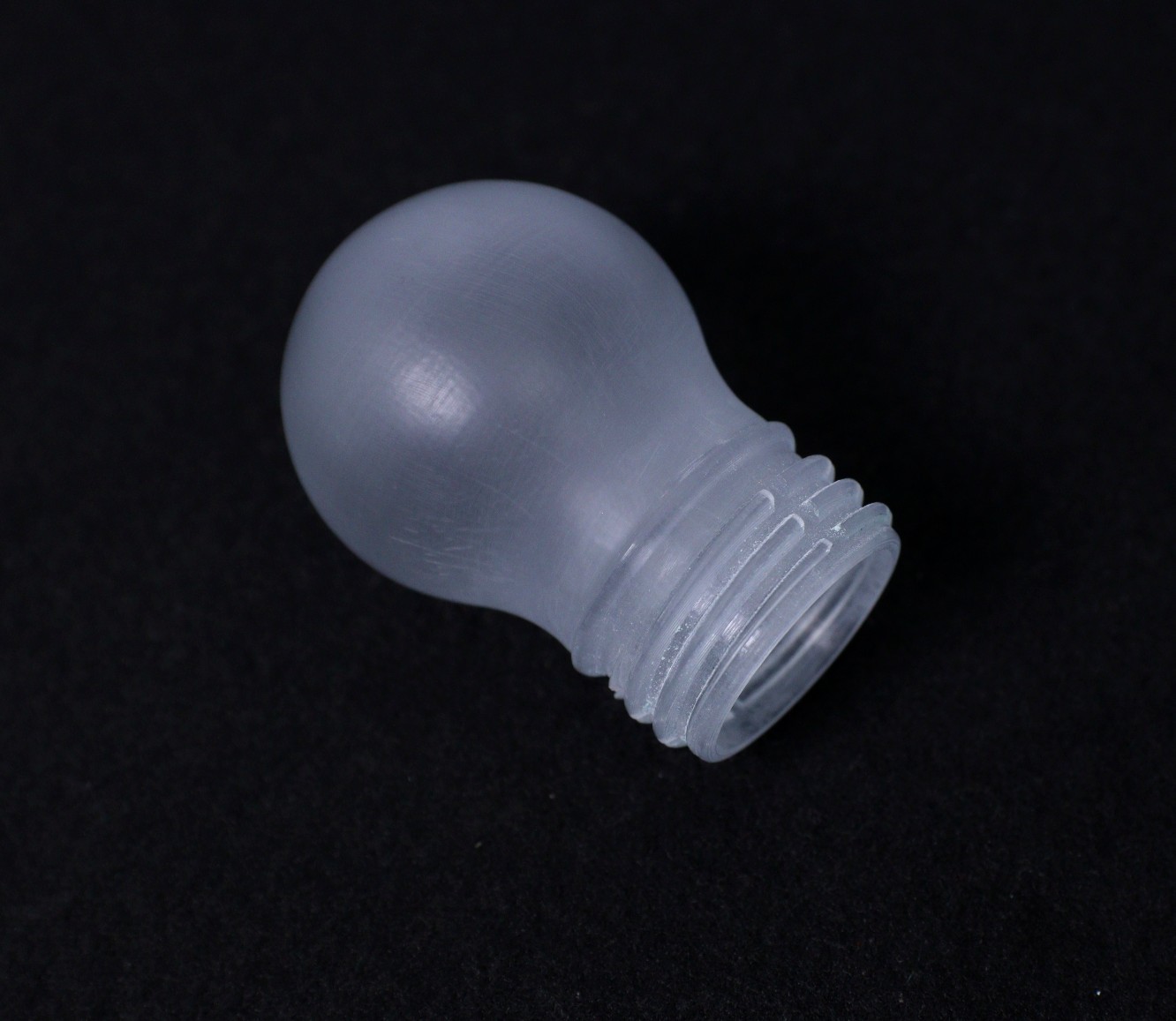
Bulb Attachment:
This part is an optional part, I just printed it to check how it works with the original lamp design. I can say it looks far better than what I have expected earlier.
![]()
Rubber Parts:
In my designs, two parts are made of TPU, and I have struggled a lot to make these two parts. After a long time search, one vendor made it for me. But the outcome is not satisfactory. I think when I give mass order, maybe get good quality parts.
-
Solar Panel Arrived and Listed On Tindie Store
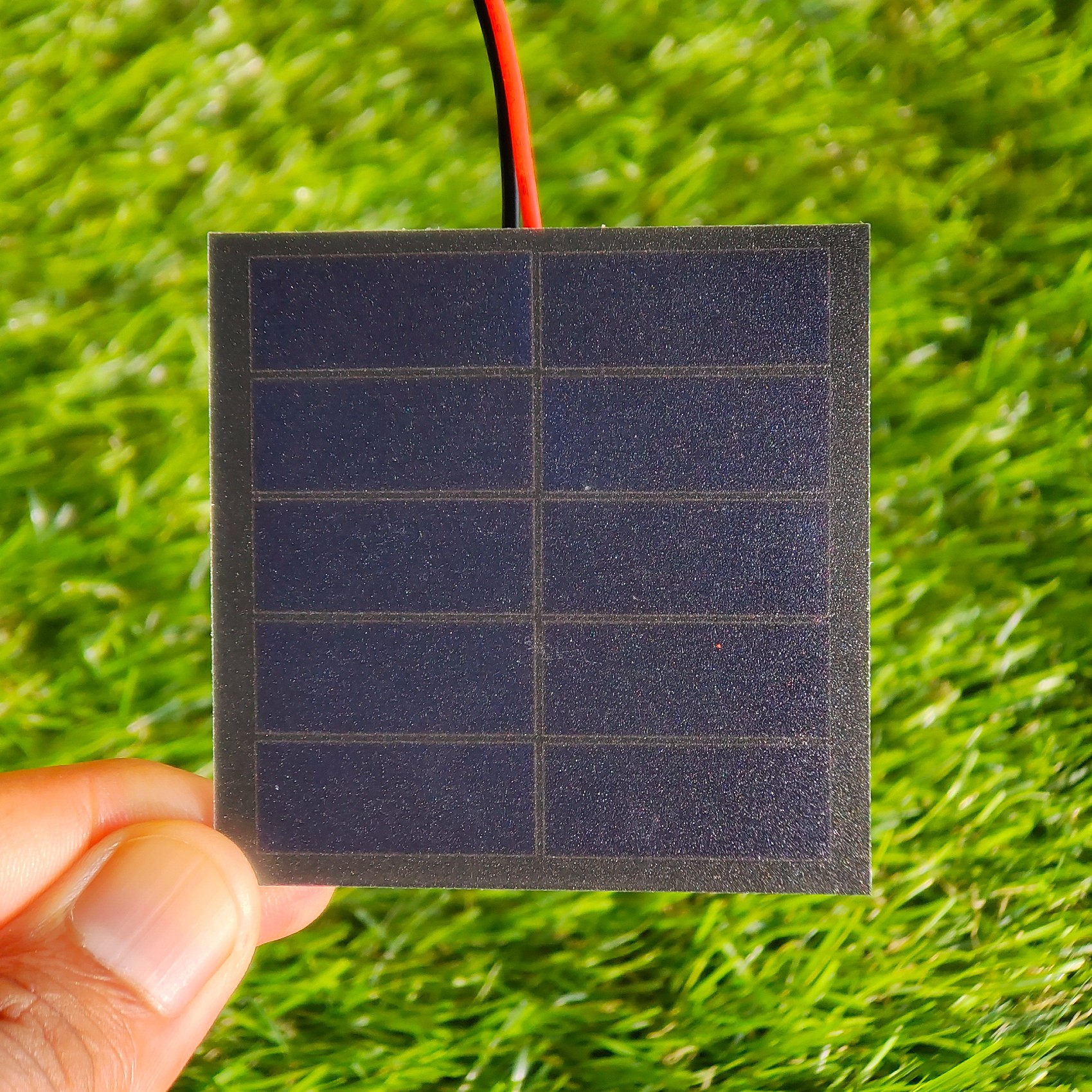
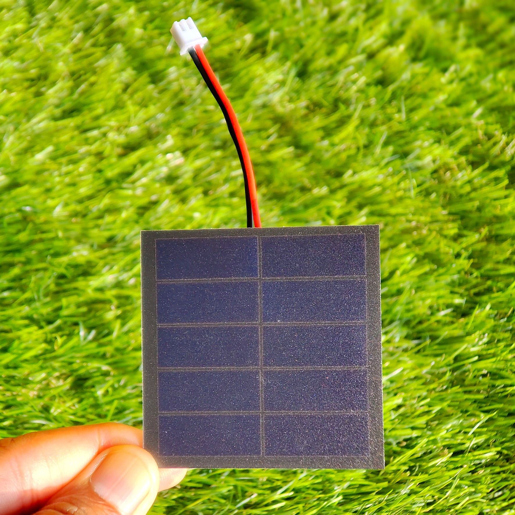
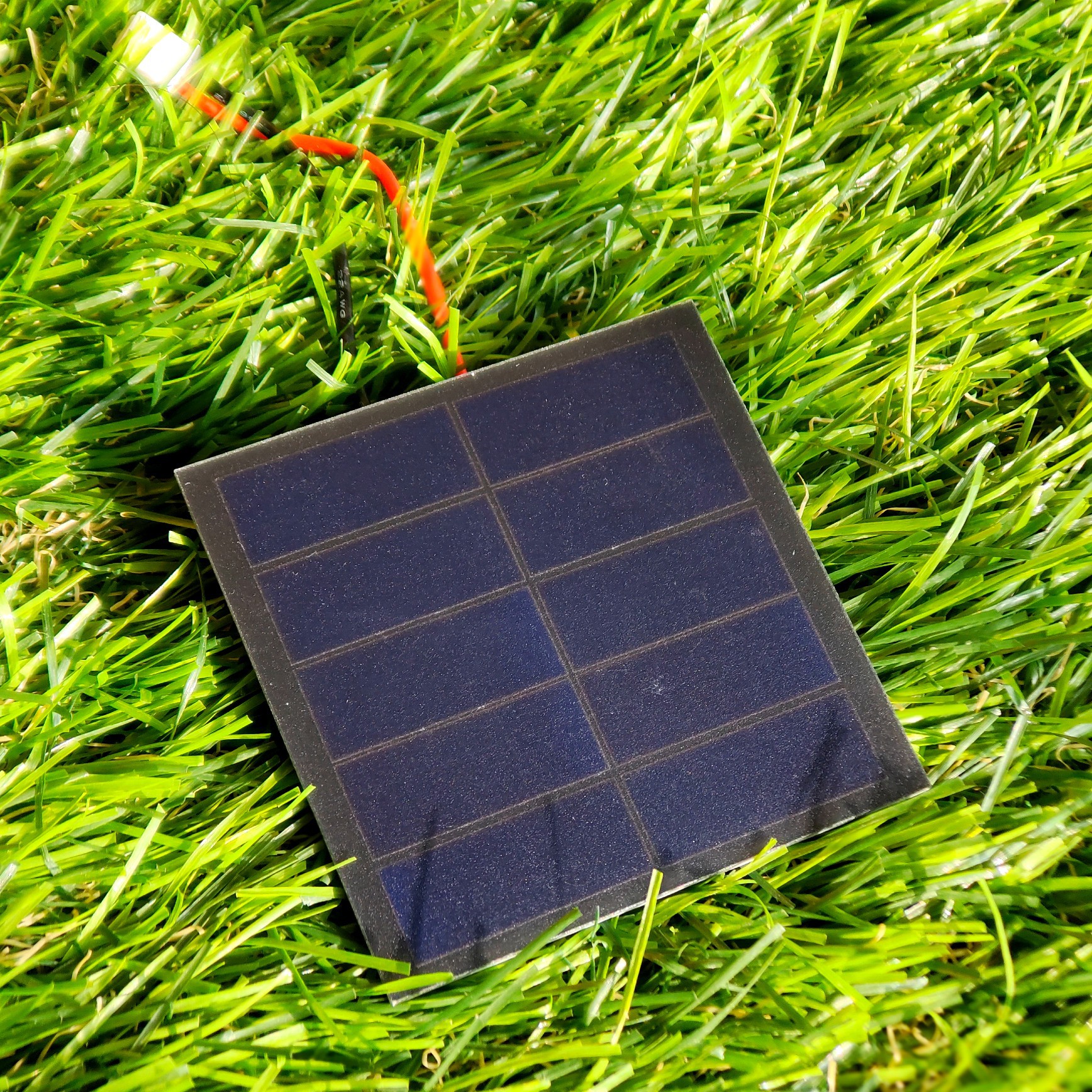
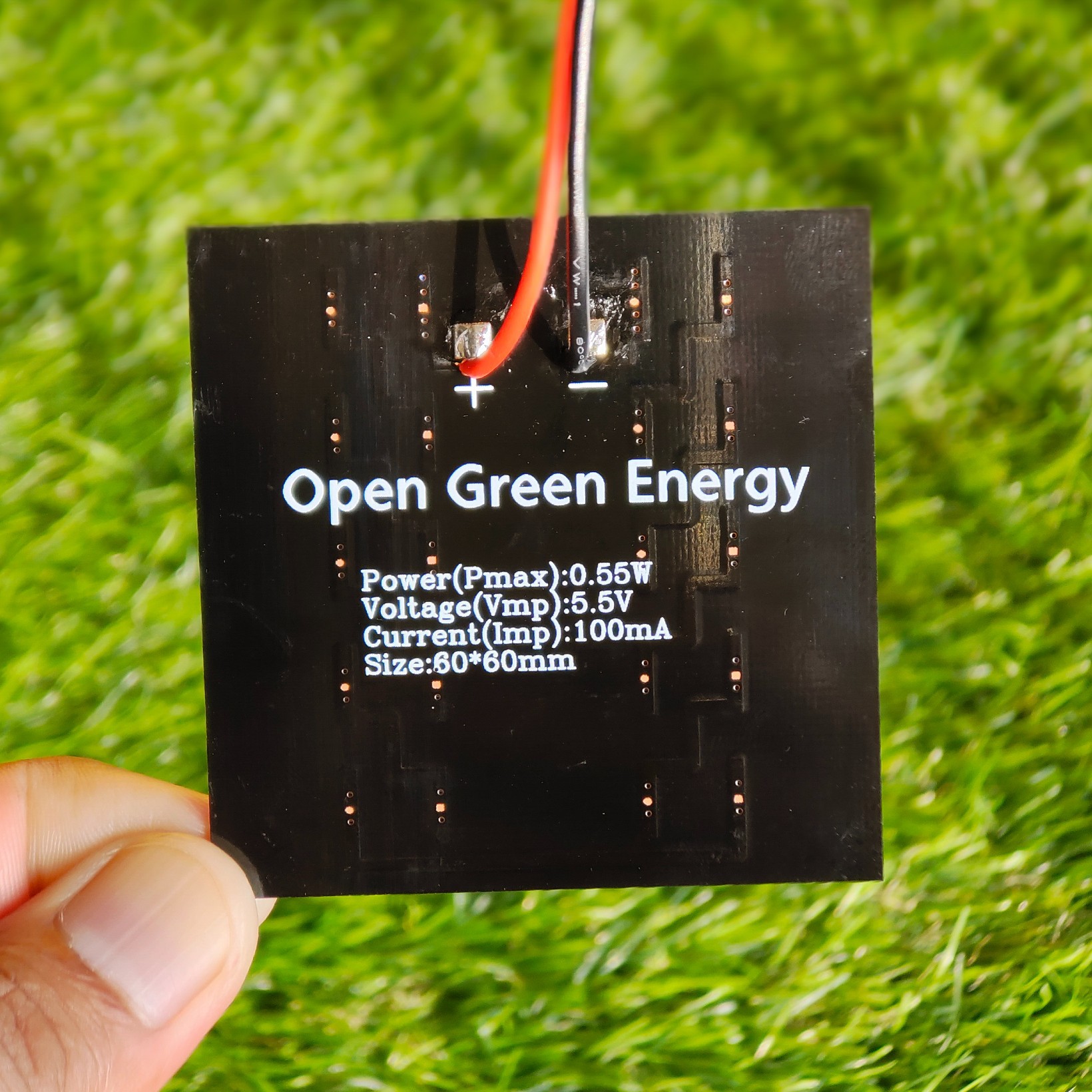
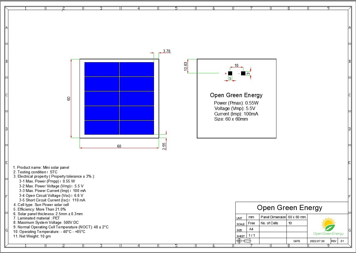
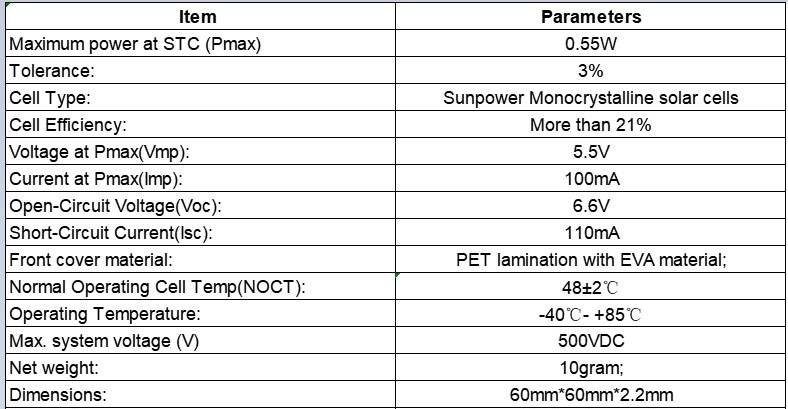
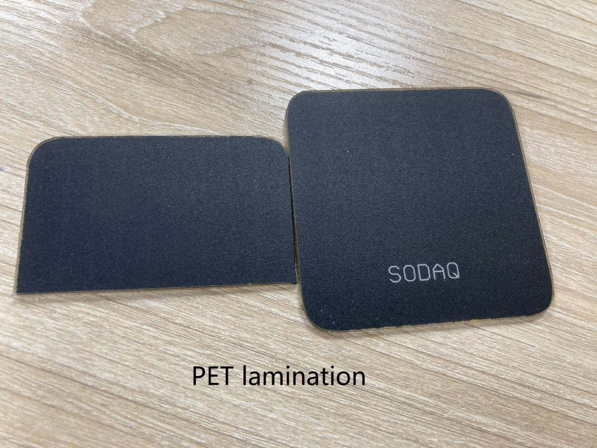
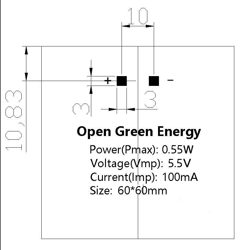
08/09/2022 at 10:35 • 0 commentsI received my customized solar panel today. The quality of the solar panel is extremely good, you can see the actual pictures. The panel is rated for 0.55W / 5.5V and is suitable for outdoor charging of Li-ion/LiPo batteries.
This panel is much more efficient, Quality assured, and Reliable than the commonly available Solar Panels on the market today. The efficiency of cheap solar panels available in the market is in the range of 14-17% whereas this solar panel is assured to give more than 21% as it uses high-efficiency solar cells from Sunpower.
I have listed the solar panel on the Tindie store, so anyone can buy it now. You can use this panel for any of your DIY projects which are powered by a single-cell lithium-ion / LiPo battery.
Tindie Link: https://www.tindie.com/products/opengreenergy/055w-55v-mini-solar-panel/
![]()
![]()
![]()
![]()
Datasheet:
![]()
-
Enclosure Design Upgraded
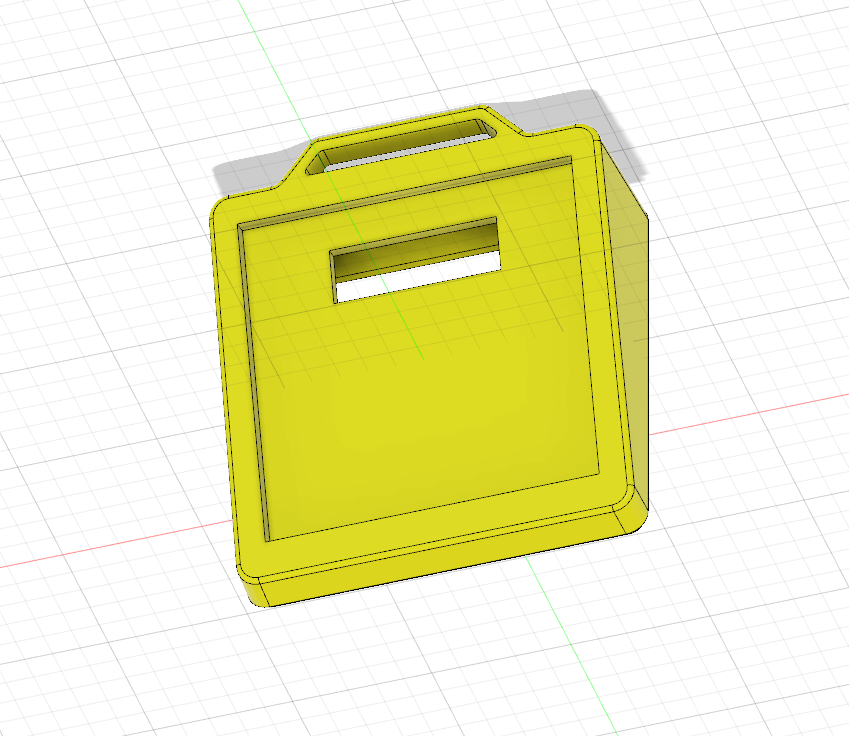
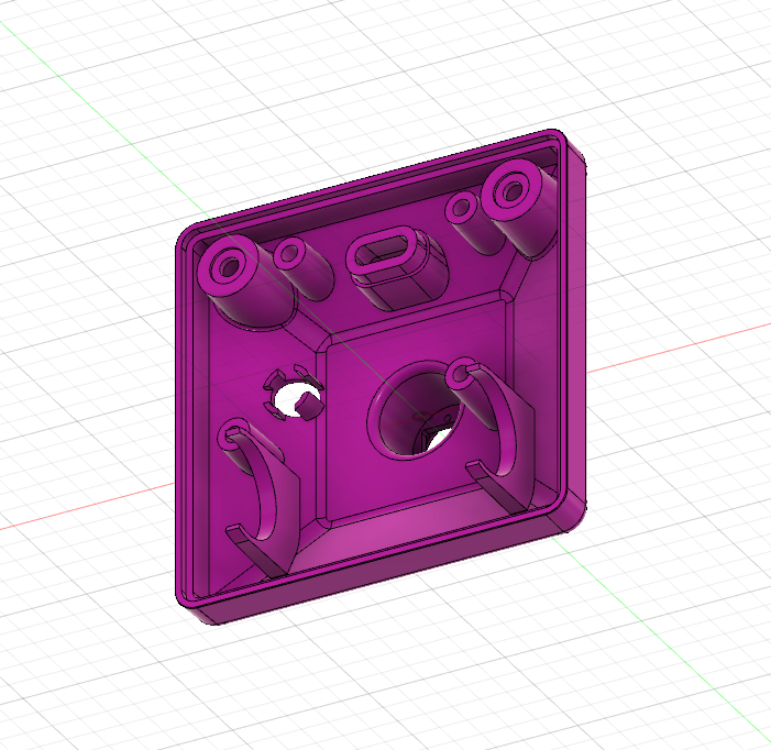
07/21/2022 at 09:42 • 0 commentsIn my previous log, I have updated that I will use a 18650 battery instead of 14500 battery and SMD LED instead of a straw hat LED. Due to these changes, the old enclosure will no more work. So, I have redesigned the enclosure to accommodate the bigger battery and SMD LED. The new design also included an arrangement for hooking this lamp to a backpack during camping and trekking, so that the battery will charge continuously.
Pictures for new Enclosure Design :
![]()
![]()
![]()
![]()
![]()
![]()
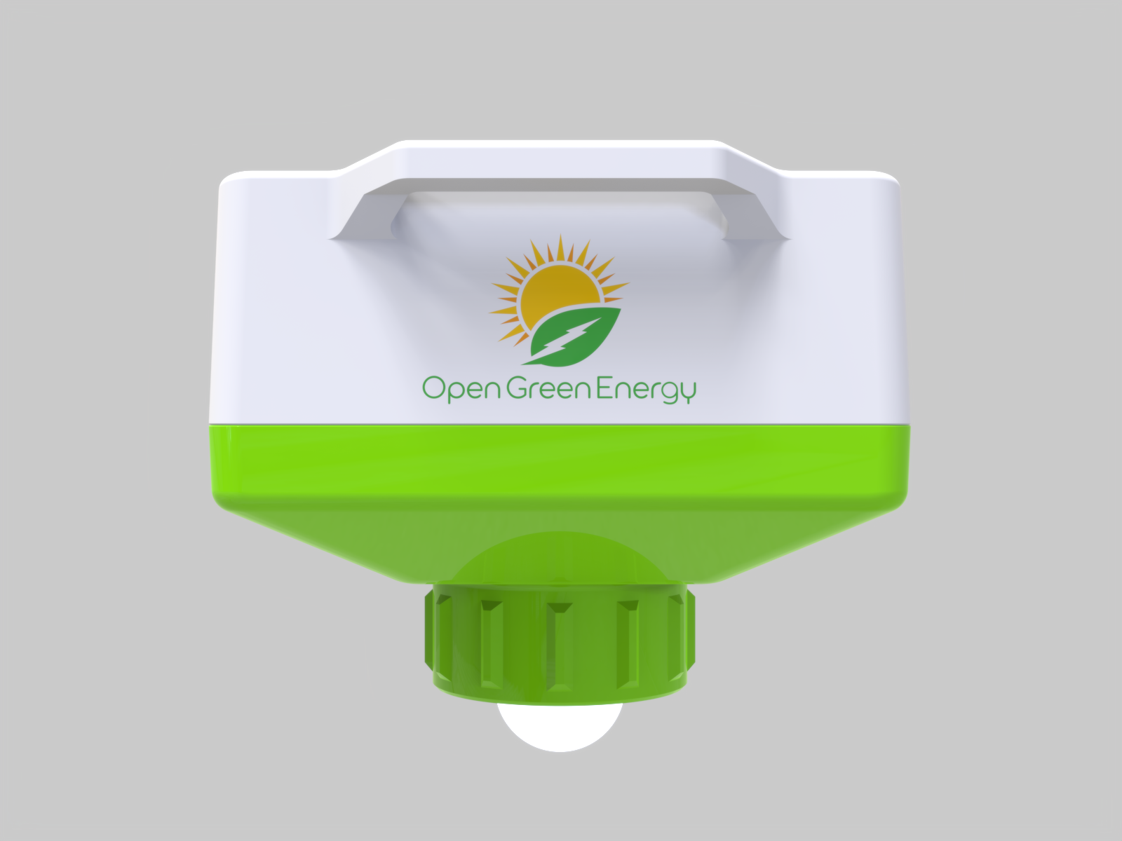
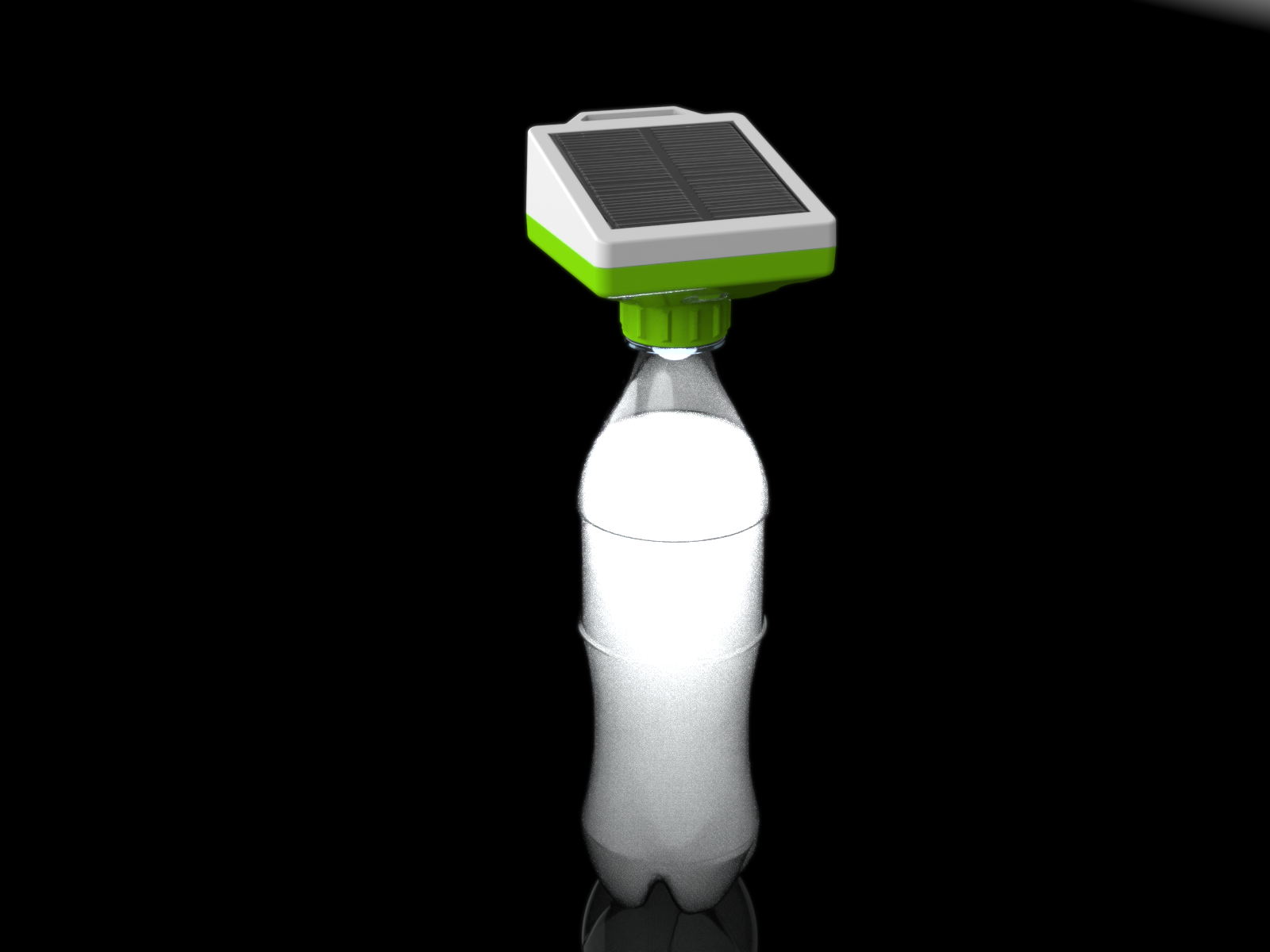
Rendered Picture of Final Product :
![]()
![]()
-
PCB Updated to V2.0
07/14/2022 at 04:31 • 0 commentsI have designed a new PCB as per the schematic V2.0. There are two different PCBs
1. Main Board
2. LED Board
Main PCB Board:
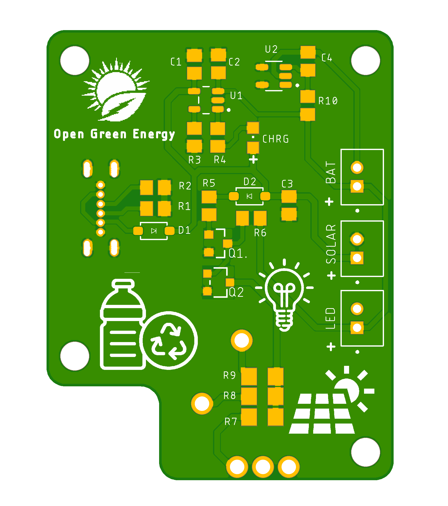
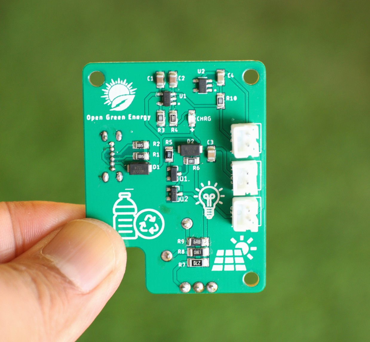
The main PCB includes all the circuits for charging the battery, LED driver, and battery protection. I have used all the SMD components with the 0805 packages ( except the LED current limiting resistors R7, R8, and R9 which are 1206 packages) so that they can easily be hand soldered.
![]()
![]()
LED PCB Board:
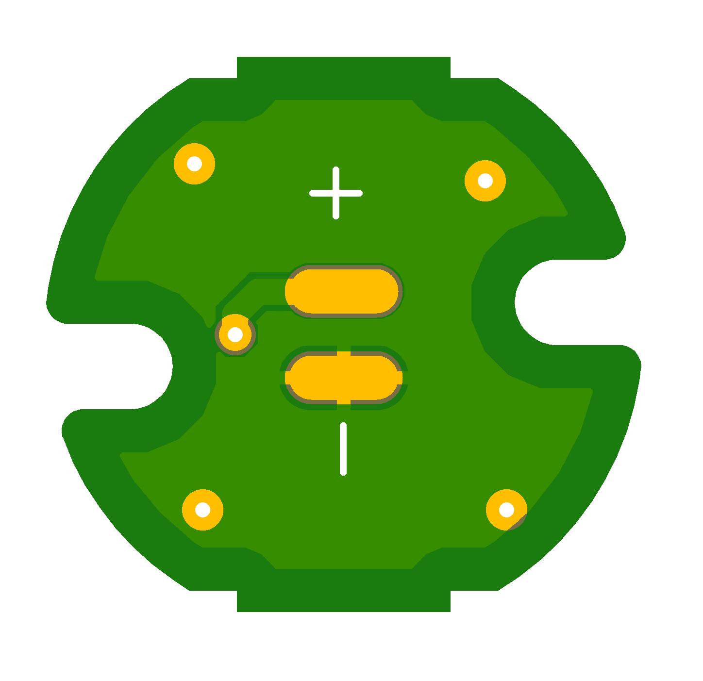
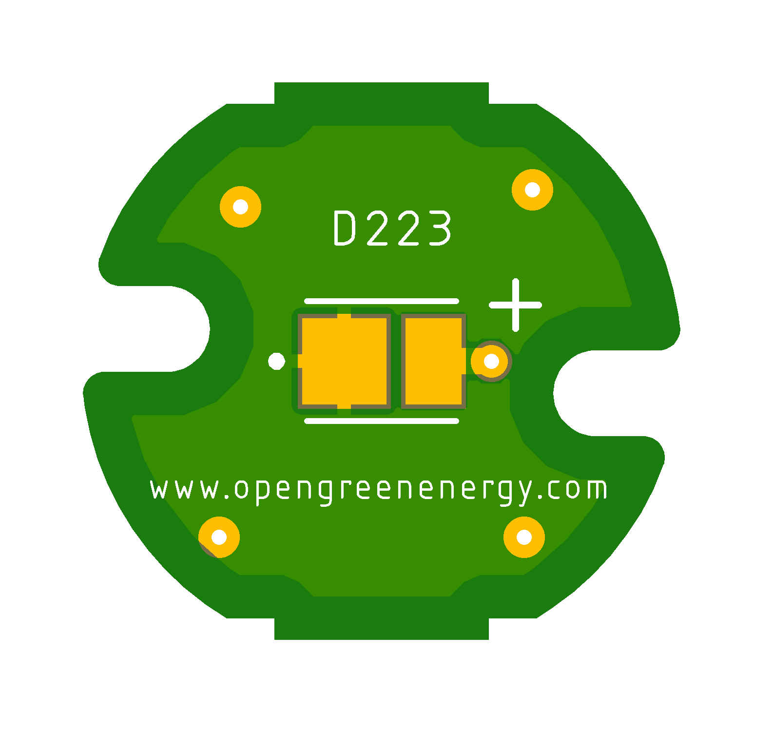
The LED PCB board only uses the 0.5W SMD LED ( 2835 package ).
![]()
![]()
Update 02.08.2022
PCB Arrived :
I ordered the PCB from PCBWay, the PCB arrived within 7 days. The PCB quality is really awesome.
Following are the images of assembled PCB.
![]()
![]()
![]()
-
Selecting the Solar Panel
07/06/2022 at 17:48 • 0 commentsThe calculated Watt-hours required to drive the LED is 2.75 Wh, considering peak sun hour is 4.5 for most places in India, the solar panel size shall be as follows:
Considering the Battery Efficiency 90%, the effective Wh required = 2.75/ 0.9 = 3.05 Wh
Sun Hours = 4.5 Hrs
Solar Panel Wattage = 3.05/4.5 = 0.679 W
So we need a solar panel larger than the above-calculated value ( 0.68 W ). The available area in my enclosure to place the solar panel is 60 x 60 mm2. The suitable voltage for the solar panel to charge the 3.7V battery is 5.5V. There are many 5.5V solar panels available in the market with this standard size, the typical wattage is in the range of 0.4 -0.45W.
Finally, I decided to use Sunpower solar cell to get the maximum possible wattage ( 0.55W) within this limited area. Following are the specifications of the Sunpower Solar panel, that I am going to use in my final product.
![]()
Sample Picture Of Sunpower Solar Cell:
![]()
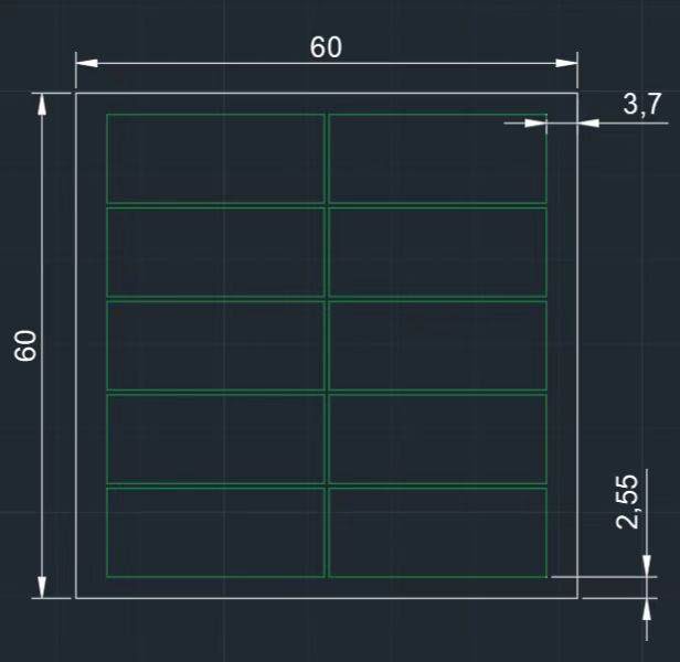
Solar Panel Layout:
1. Top Side
![]()
2. Back Side
![]()
-
Schematic Updated
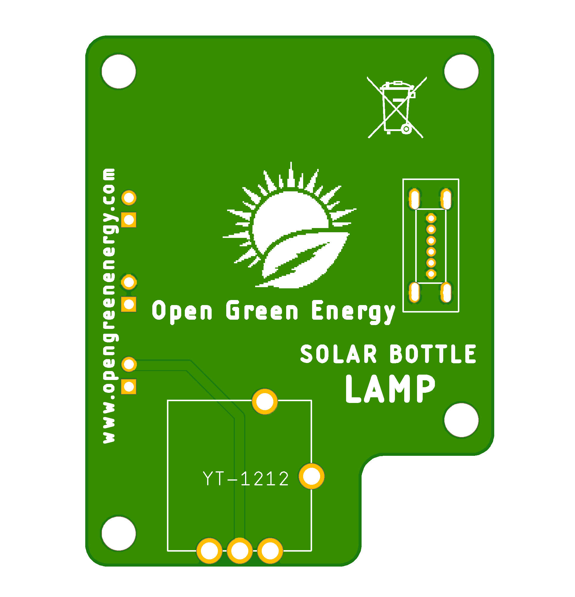
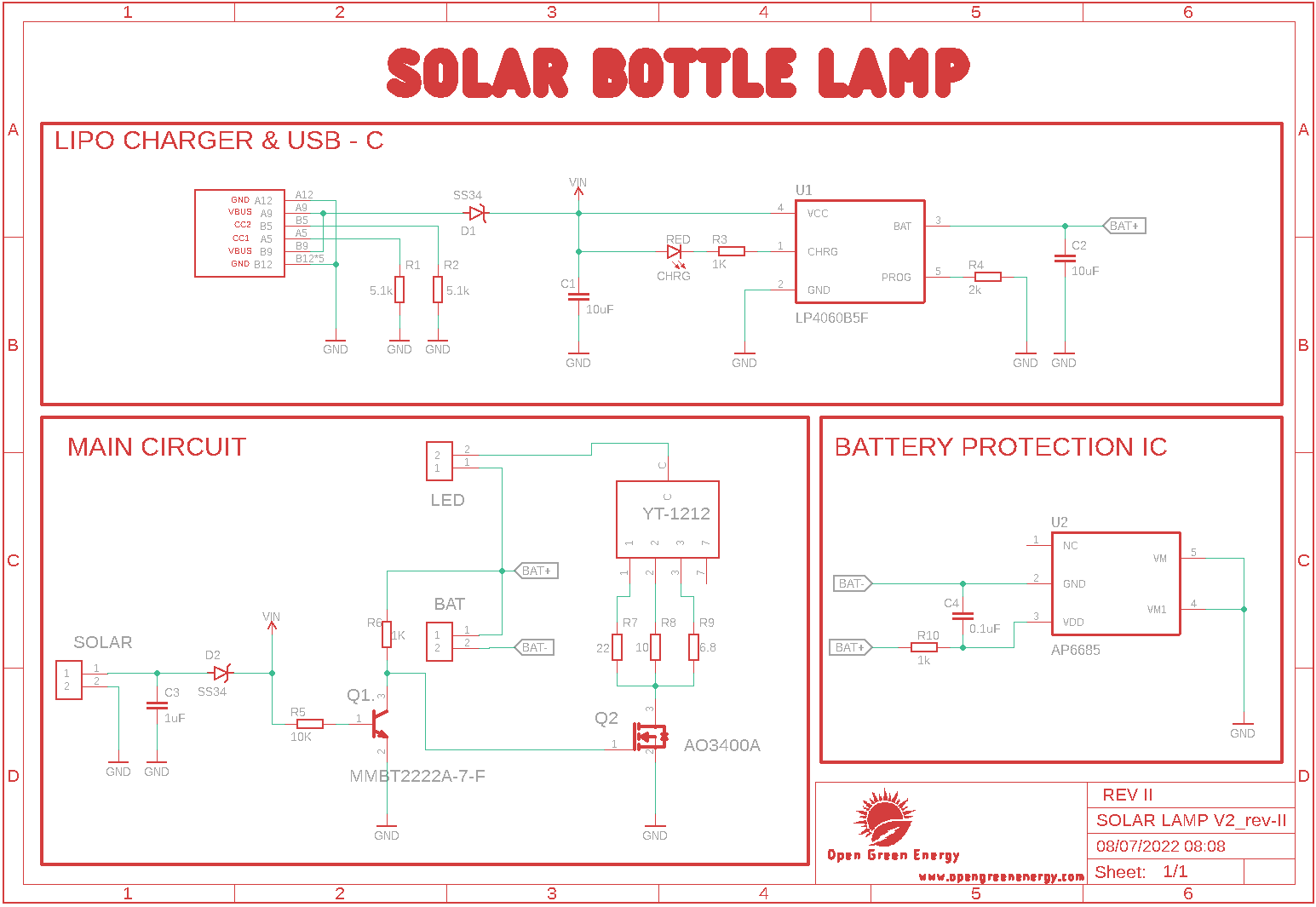
07/06/2022 at 17:01 • 0 commentsIn my earlier schematic (V1.0), the solar panel is the only source to charge the battery. However, due to the limited area of the lamp, the solar panel mounted on the lamp is not sufficient to charge the larger capacity battery. So I have added a USB port (Type-C) to charge the battery faster. You can use an external solar panel or any USB source to charge the battery. It is also useful for sunny days when the panel doesn't receive sufficient solar radiation.
New Schematic:
![]()
Details of USB-C Port :
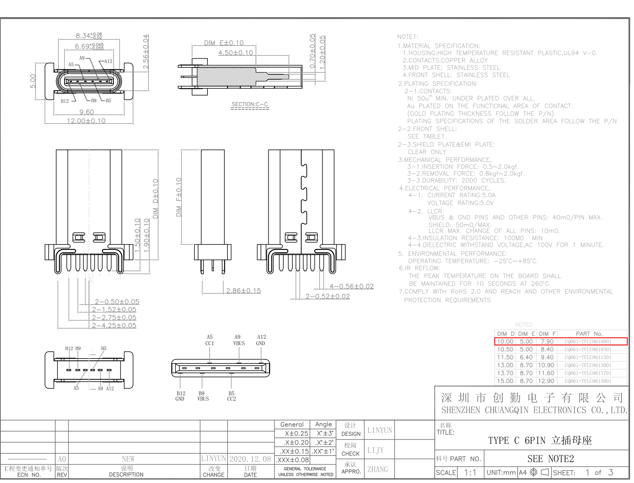
I am using the vertical mount USB port as shown in the below picture. The dimensions are D=10.0, E=5.0, and F=7.90.
The pinouts are as tabulated below:
B12 B9 A5 B5 A9 A12 GND VBUS CC1 CC2 VBUS GND ![]()
-
Updating to New Switch
07/01/2022 at 05:28 • 0 comments![]()
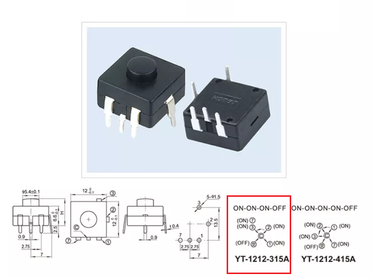
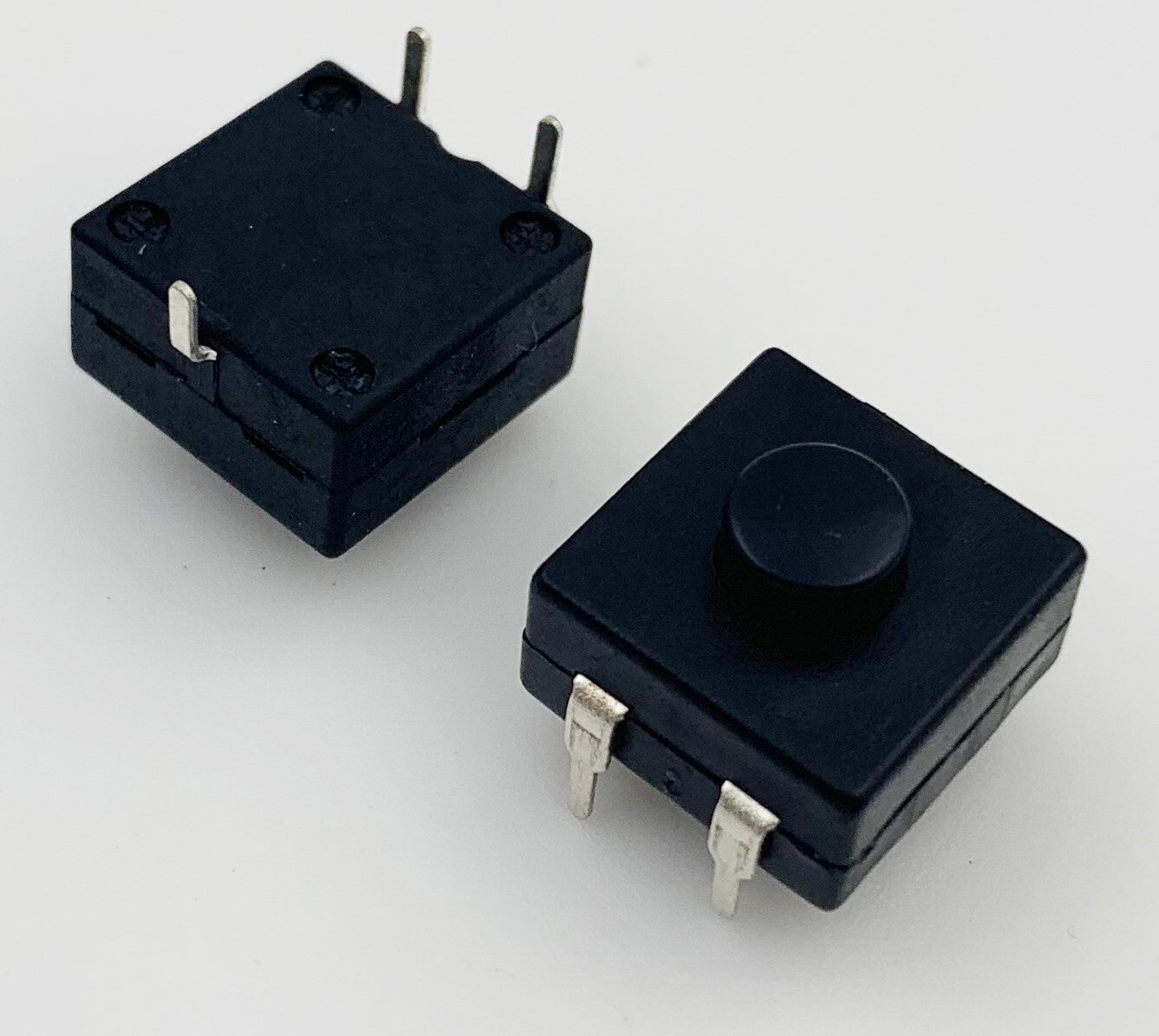
I am going to use a 5-pin switch with has 4 modes of operations as shown in the above image. By using this switch I will be able to operate the LED in the following modes:
Mode-1: ON - High Intensity
Mode-2: ON - Medium Intensity
Mode-3: ON - Low Intensity
Mode-4: OFF - Turn Off the LED
![]()
Earlier I have used a 3-pin button switch for 3 different modes of operation as given below.
Mode-1: ON - High Intensity
Mode-2: ON - Low Intensity
Mode-3: OFF - Turn Off the LED
![]()
DIY Solar Bottle Lamp
Solar Bottle Lamp is a solar-powered light that is constructed from waste plastic bottles. The design idea is to reuse waste plastic bottles
 Open Green Energy