Mike Rigsby
-
Ozzy Speaks
04/24/2023 at 16:23 • 0 commentsIn this section, Ozzy gets a voice.
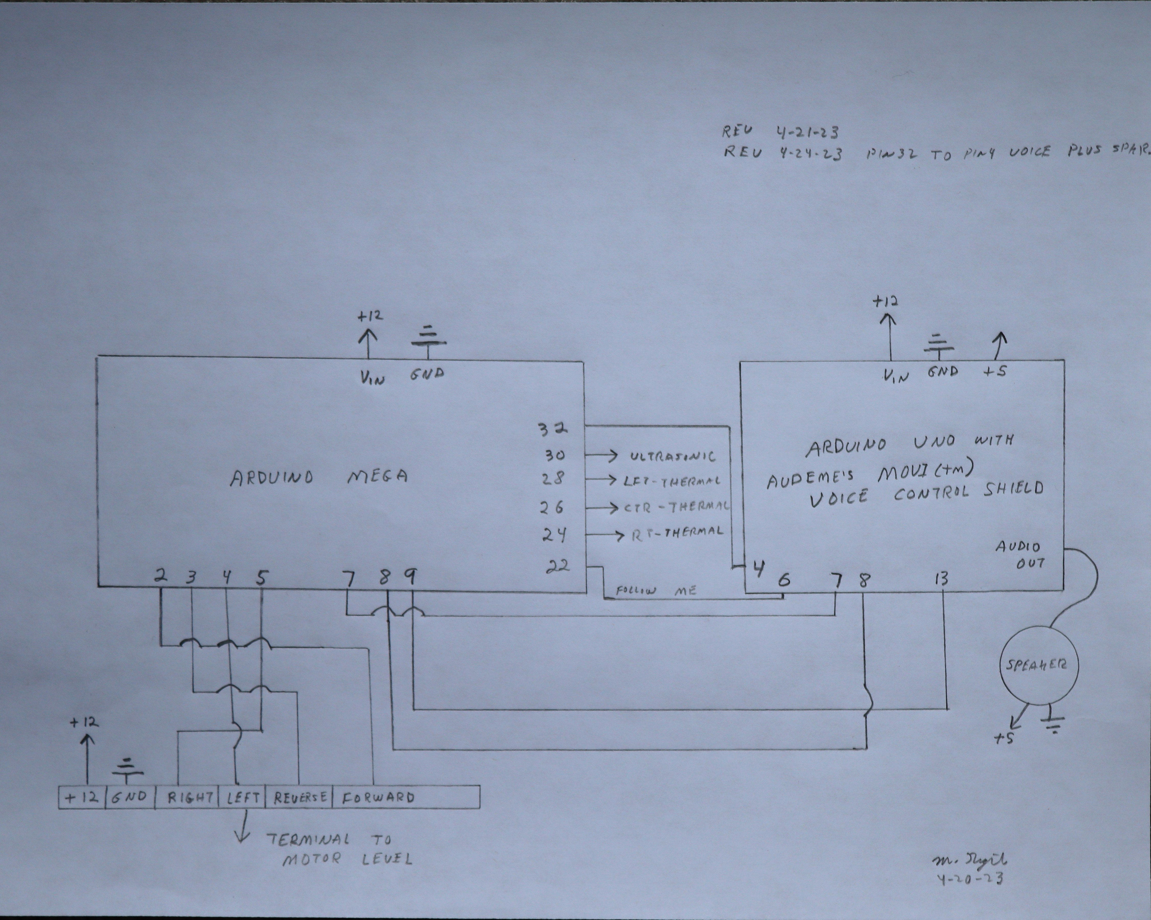
This required adding a speaker and speaker power (five volts) according to the schematic below.
![]()
This required a connection from pin 32 of the Arduino Mega to pin 4 of the voice control module.
![]()
"Ozzyvoice0424" was modified to accept voice output statements, while "homely master0424" was modified to send the "detected human target" information to the voice module.
-
Ozzy Comes on Command
04/22/2023 at 00:28 • 0 commentsNow, Ozzy will come to me when I say, "Ozzy, come here." I used an 8 x 8 thermal sensor and (another) Arduino Uno to accomplish this. After adding a "Come here" command to the voice recognition circuit, the output of the "thermal sensor Arduino system" can be used to drive the motors forward, right or left. When Ozzy gets near the target (as determined by an ultrasonic sensor), Ozzy turns around and waits for instructions.
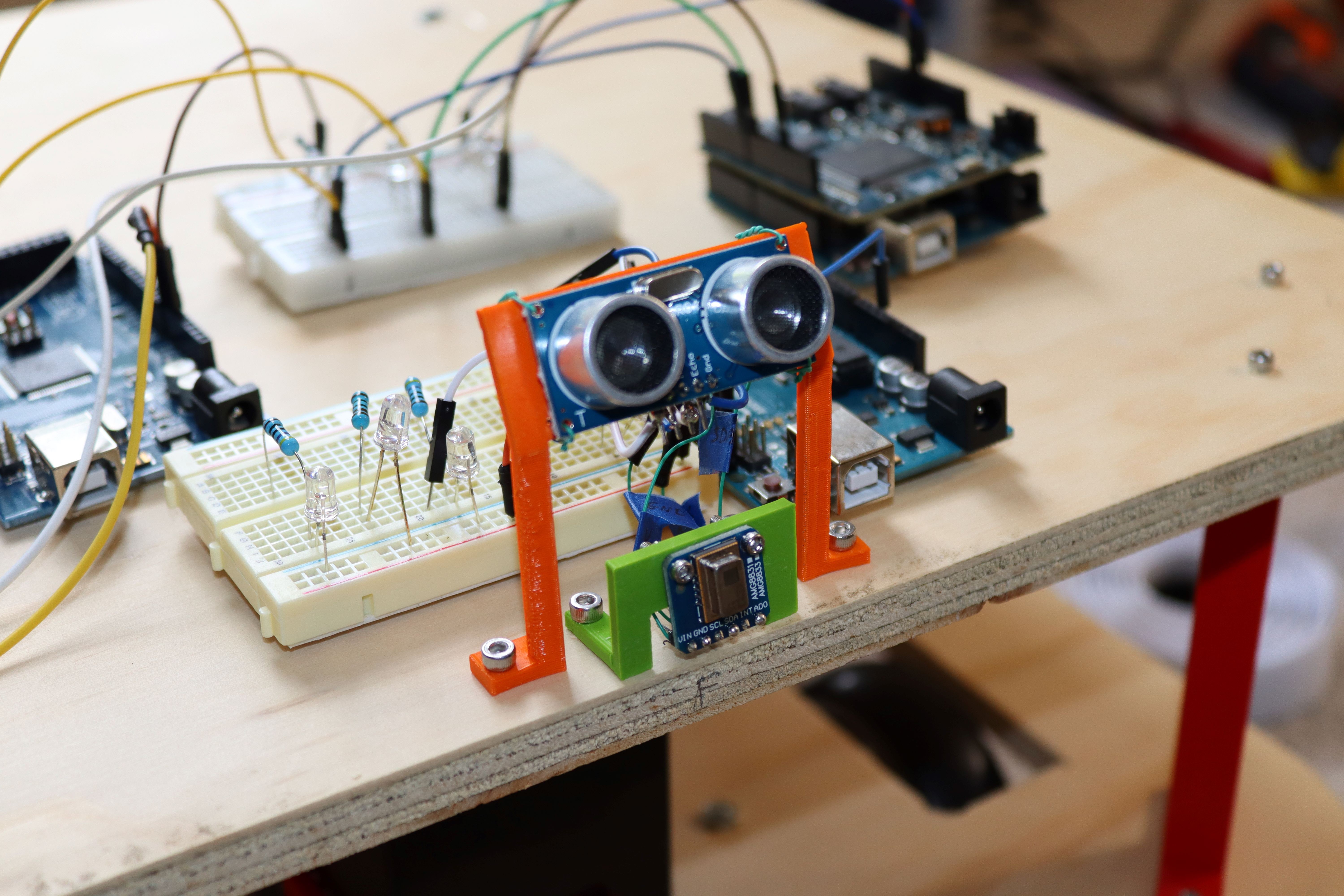
Here is the thermal sensor, mounted to the plywood using 3mm screws.
![]()
Above this is the ultrasonic sensor.
![]()
Wiring for the sensor assembly looks like this.
![]()
![]()
Changes to the Arduino Mega (master control) look like this.
![]()
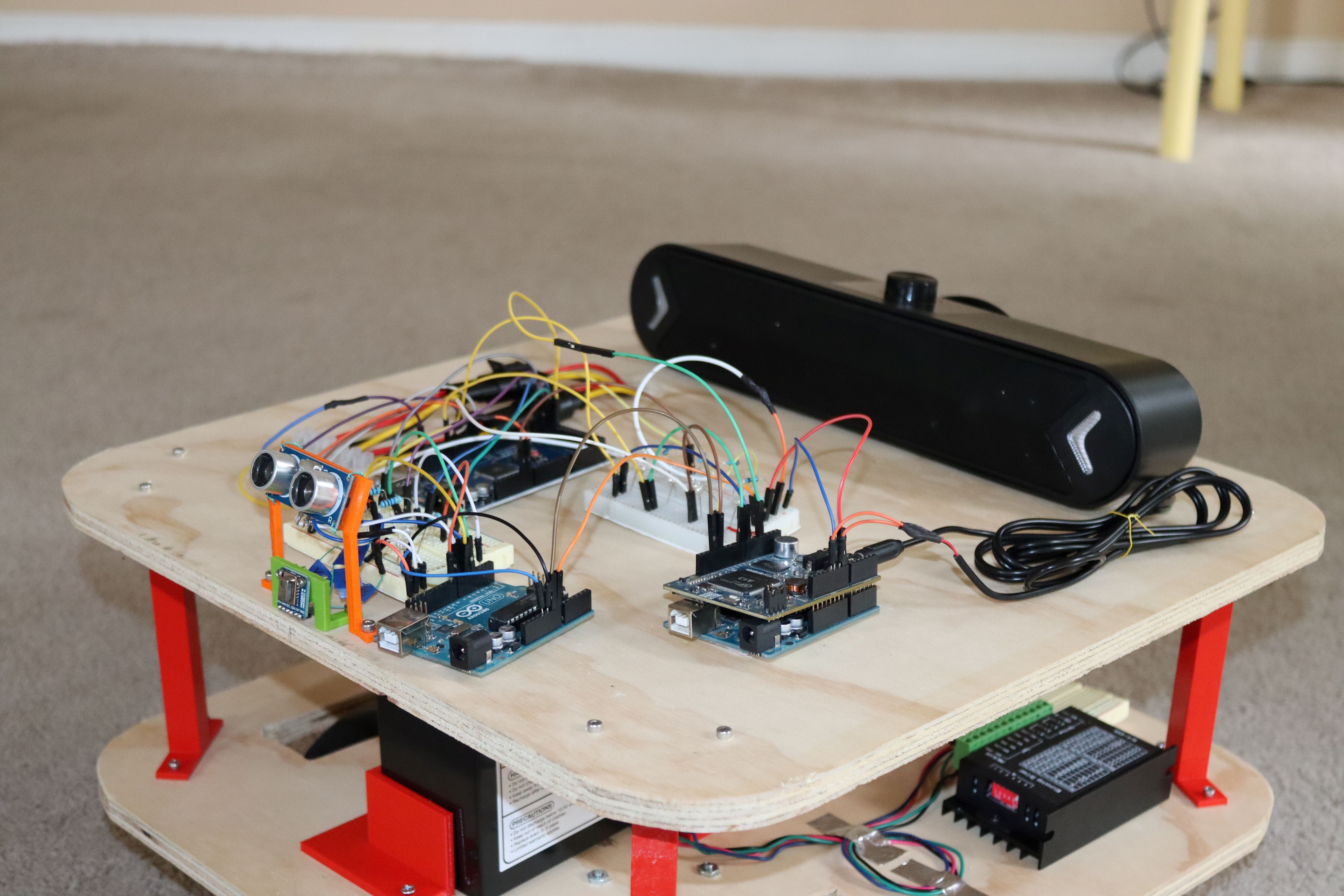
Overall, the top of the bot is getting messy and will probably have to be cleaned up at some point.
![]()
-
Voice Recognition
04/20/2023 at 19:35 • 0 commentsIn this log, I added voice recognition and named my robot "Ozzy." For speaker independent, standalone, cloudless private recognition, an Audeme MOVI (tm) Arduino shield does the job.
![]()
I can select the "wake up" word--I chose "Ozzy." Check out the Arduino code "Ozzy" for my example. The shield is also capable of producing speech; maybe I'll add that later. I connected this Arduino and shield to the master controller (Arduino Mega).
![]()
Wiring connections are made according to this schematic.
![]()
The MOVI (tm) shield must be powered by 7 volts to 16 volts on the Vin pin. It's pretty straightforward, but best to read the manual before starting.
-
Control From the Upper Deck
04/19/2023 at 21:09 • 0 commentsNow the movement instructions come from the upper deck--an Arduino Mega.
It was necessary to rewrite the software for the motor controller (stepper control test.ino) and add control lines as well as set up the Arduino Mega on the upper deck.
![]()
Movement control information can now be written to the upper deck Arduino--which will send control signals to the lower deck.
![]()
The current program (homely master.ino) merely goes forward, turns around, returns and turns around.
![]()
-
Second Layer, Sensor, Smarts, Arm
04/18/2023 at 23:26 • 0 commentsThe lower board is for power, motors and motor control. I am building a second level to manage sensors and worldly interface.
I'm starting with another piece of 1/2" plywood with four 3d printed supports.
![]()
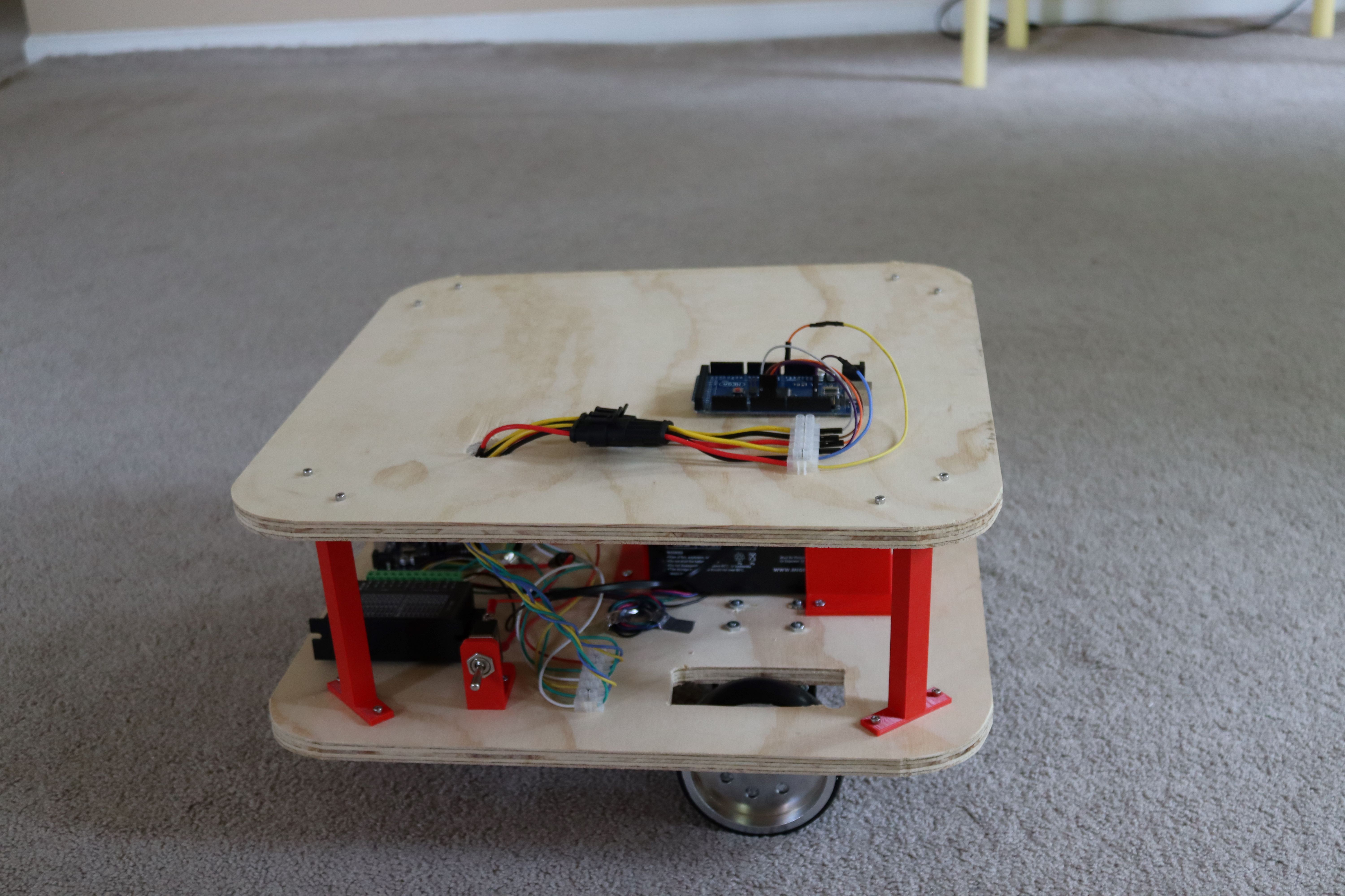
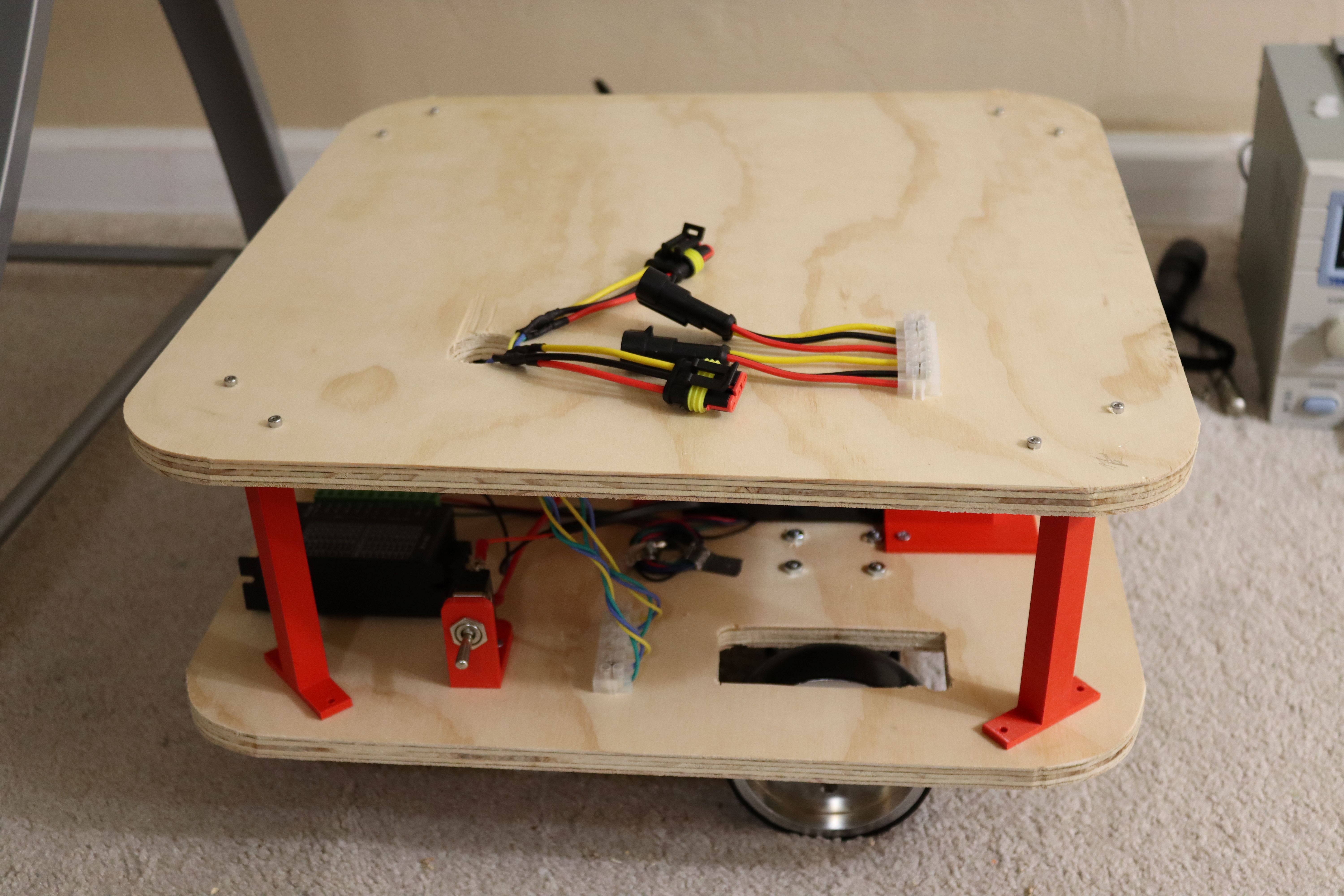
This will sit on the base unit and look something like this.
![]()
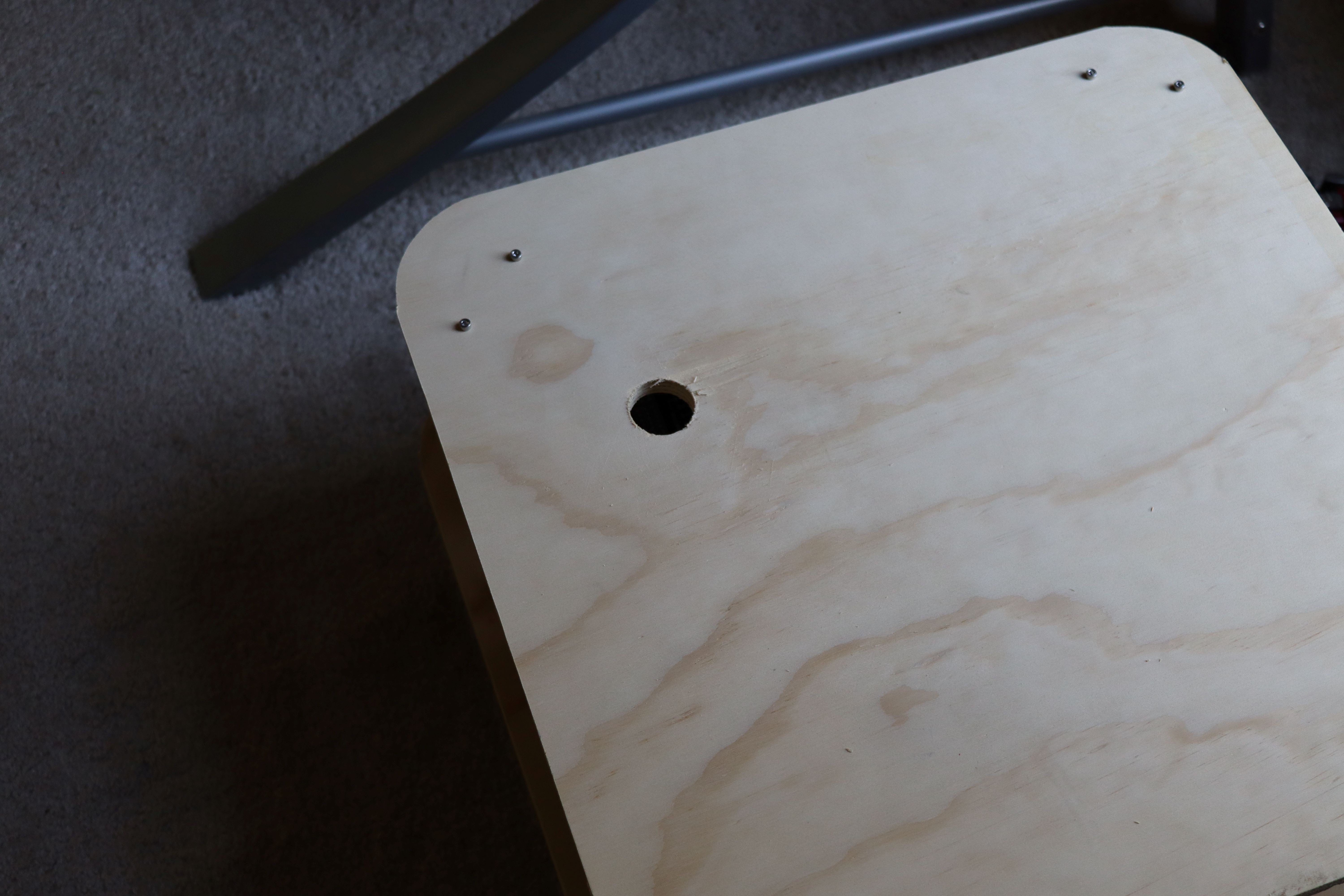
I drilled a 1 1/4" diameter hole in the upper platform to allow my one inch cable connectors to pass through.
![]()
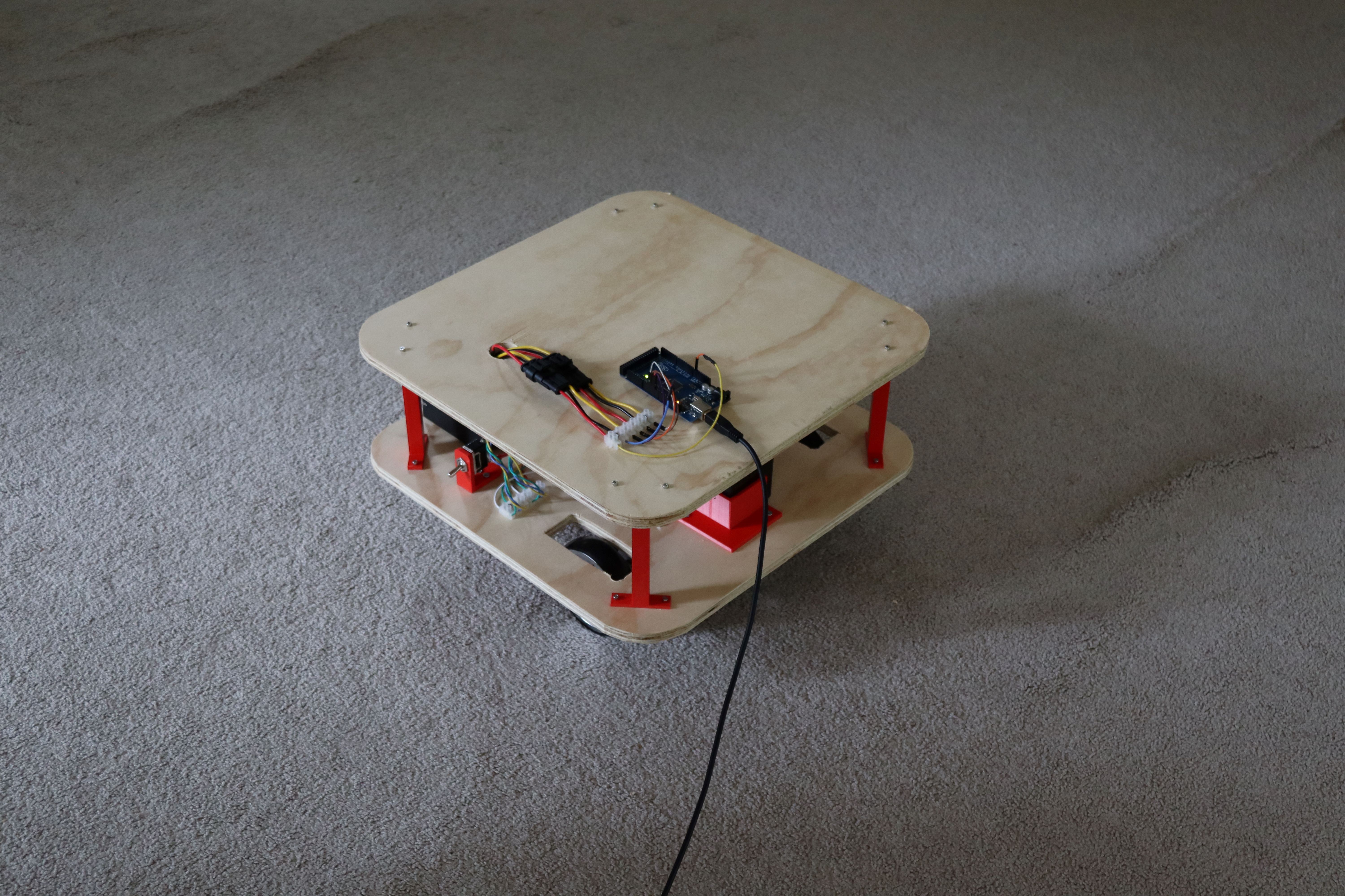
Looking at my base, I noticed that the Arduino's usb port is in a bad position if I ever want to change the motor software. I don't want to disassemble the entire bot every time I decide to make a change (that will surely occur more often than I naively plan).
![]()
I moved the Arduino and the breadboard so that I could reach them without taking the entire robot apart.
![]()
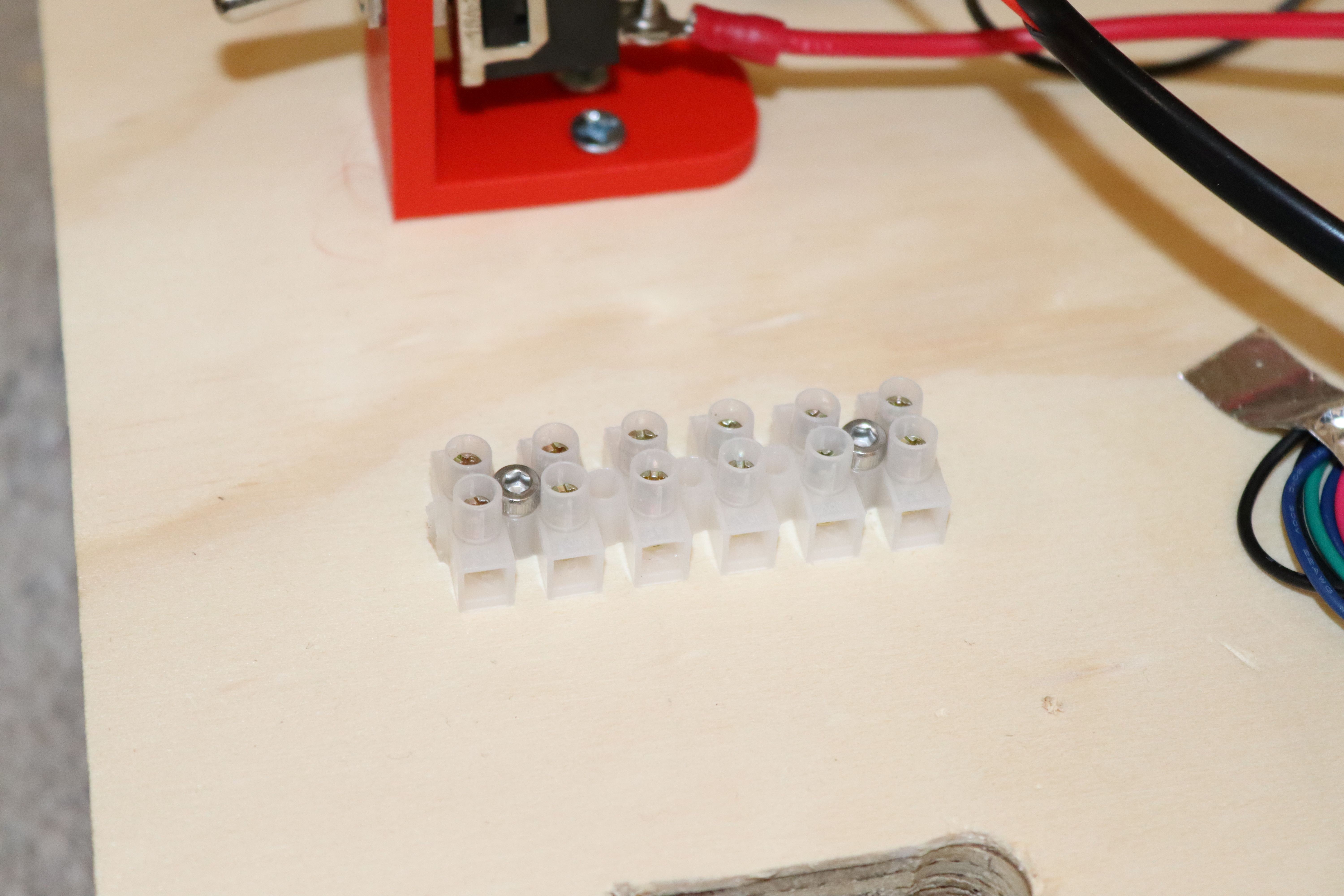
I added terminal connectors and (2) 3 pin connectors.
![]()
![]()
Securing top layer to the base with 3mm screws (20 mm length), I am now ready to start work on sensors and the first bit of control.
![]()
-
Wiring
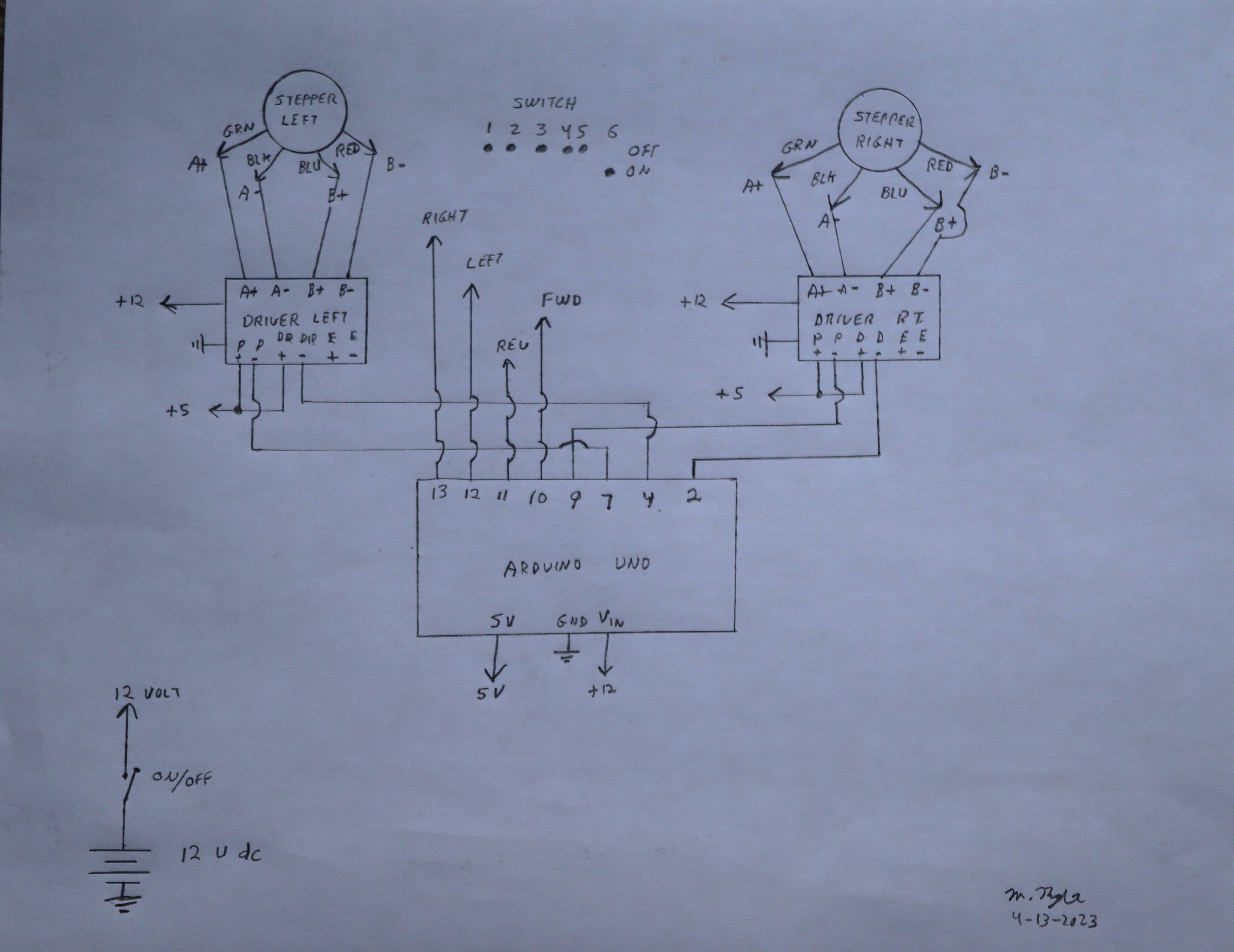
04/13/2023 at 21:39 • 0 commentsTo put this together, I have a schematic drawing.
![]()
The Arduino sketch (which just makes the machine go forward, reverse, left, right, repeat) is provided in the files.
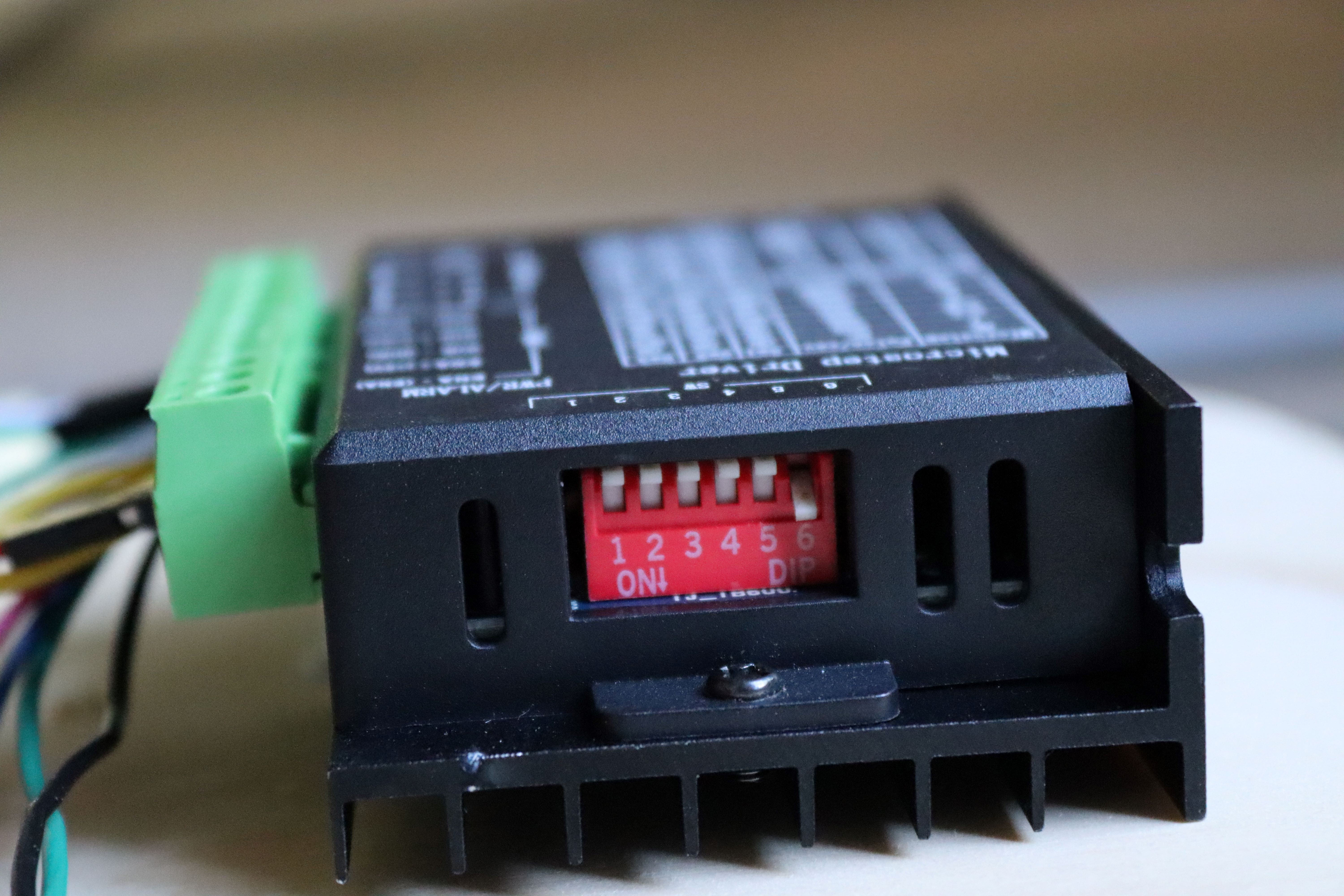
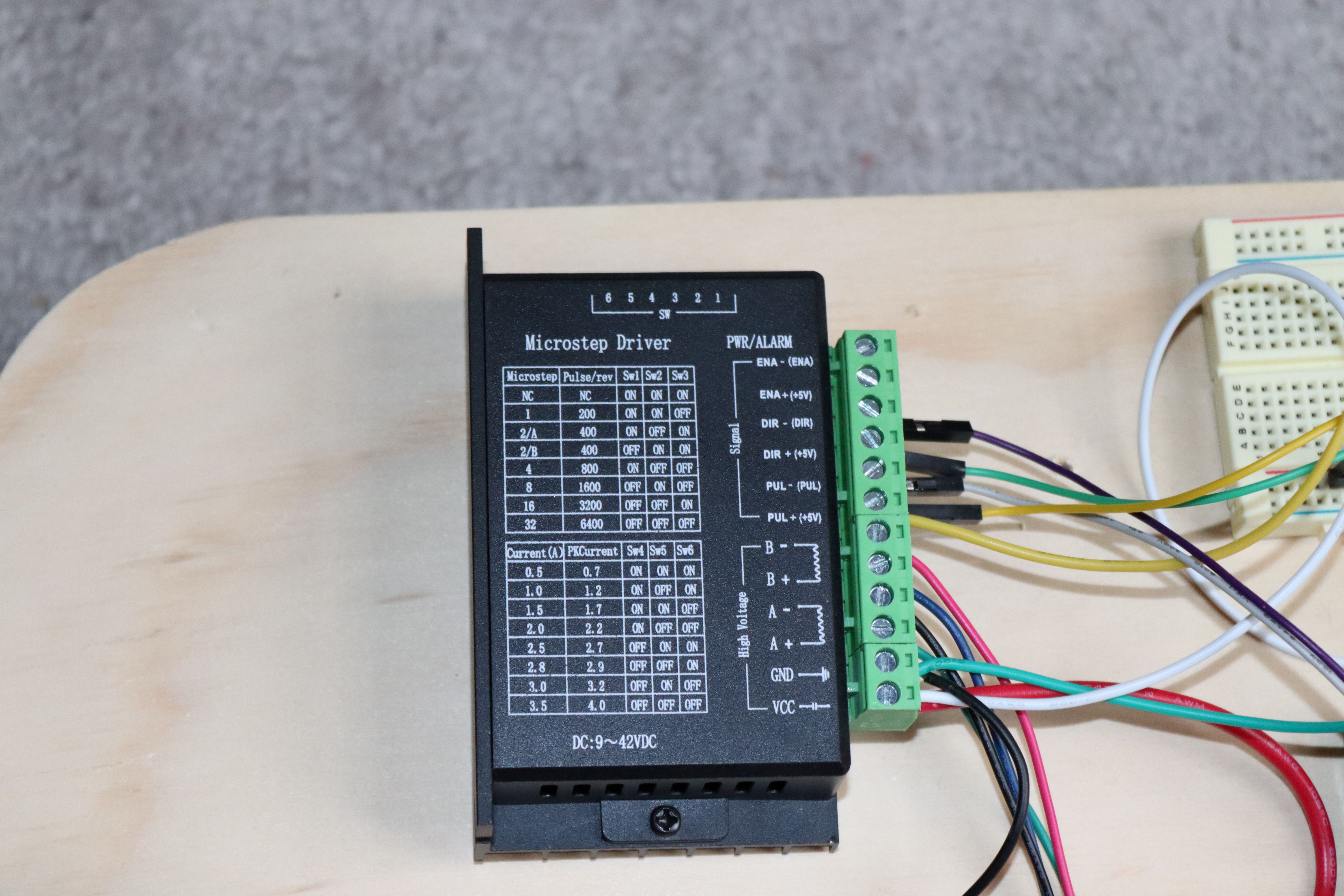
Here is a photo of the dip switches on the stepper controller. It's set for 6400 steps per revolution (I know, that's crazy--but it's smoother and less noisy) at maximum current of 2.8 amps (maximum according to the motor spec). Each motor only draws about 1.5 amps with a 12 volt supply--so I'm just dipping my toes in the world of stepper motors as far as understanding what's happening.
![]()
-
First Adjustment
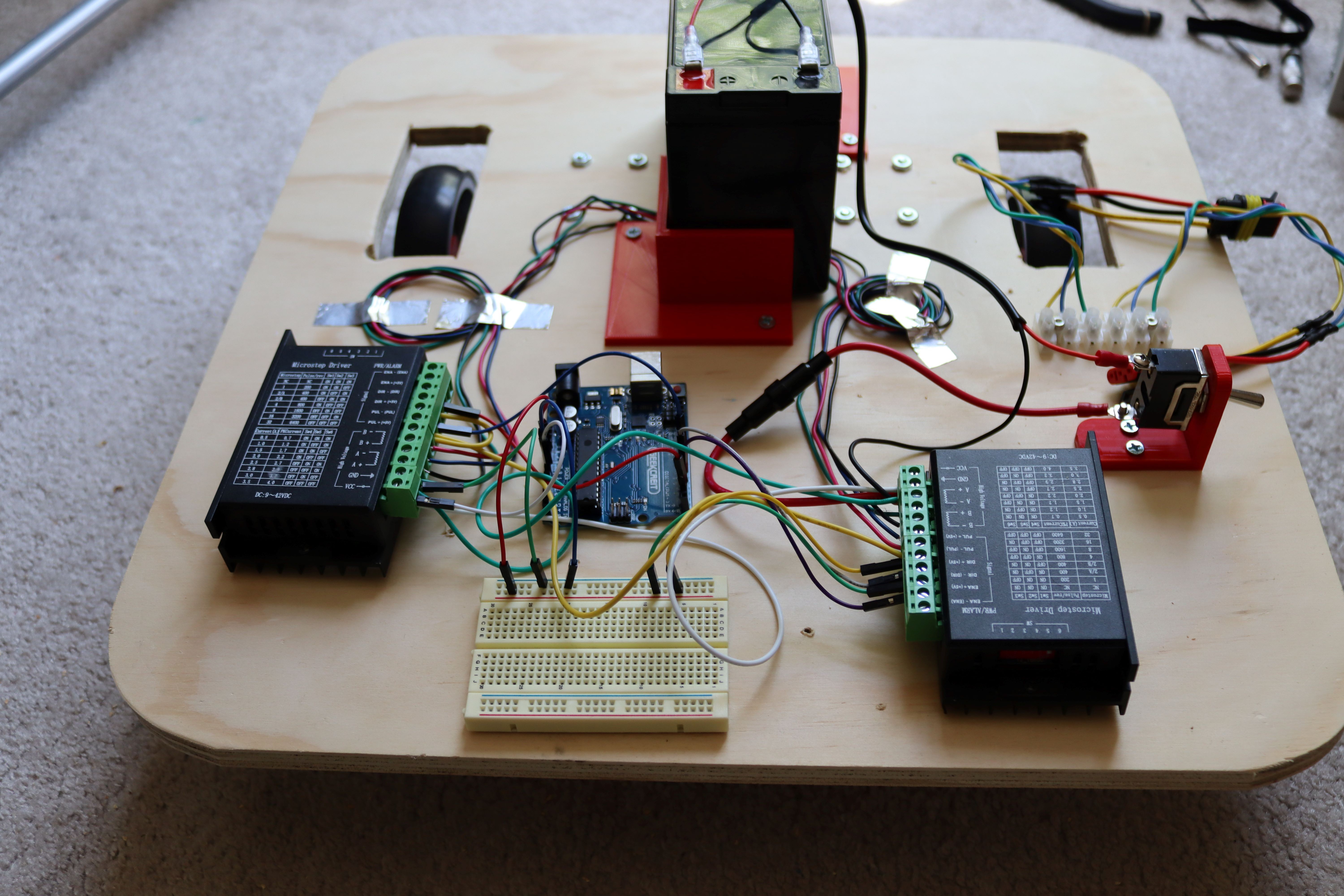
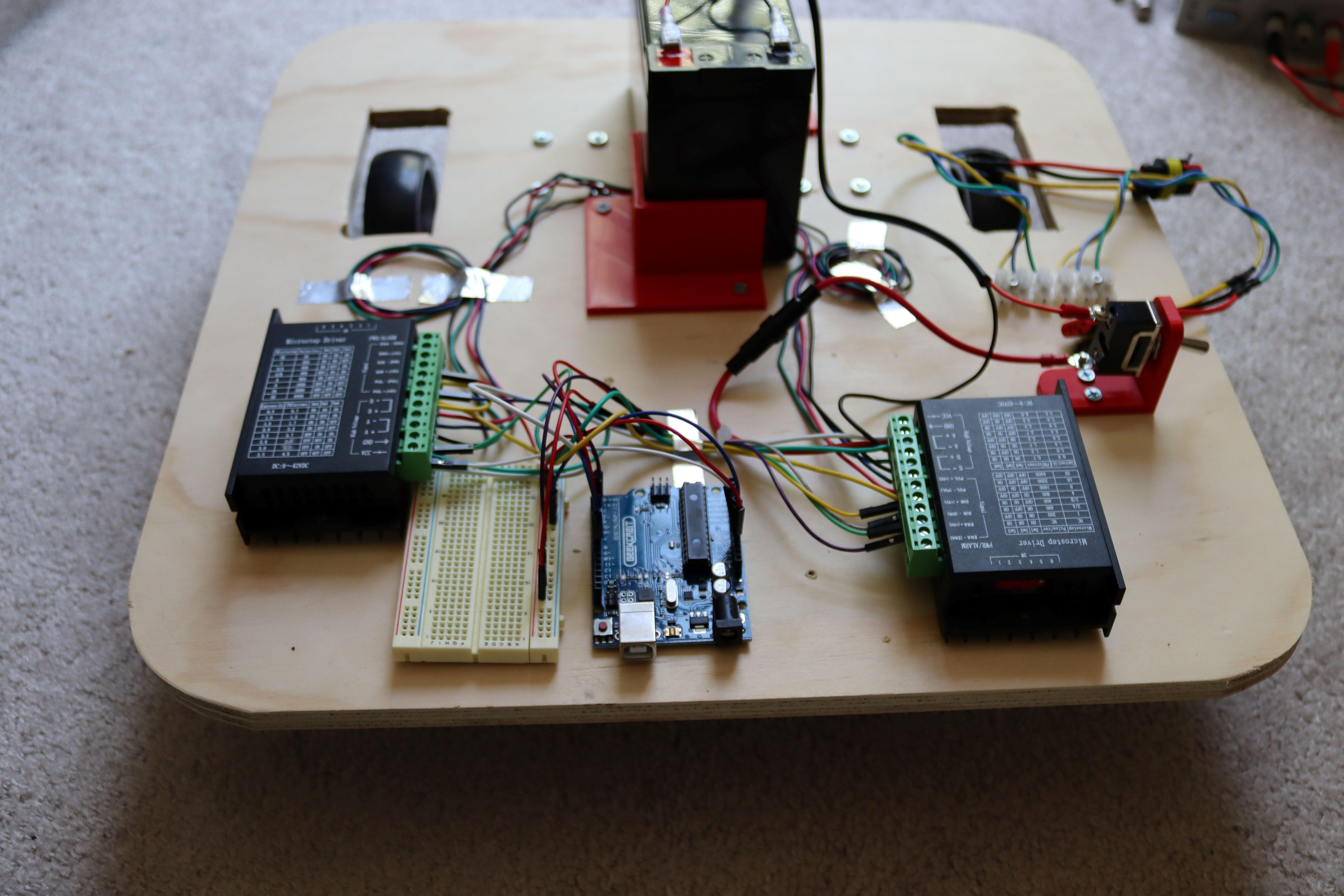
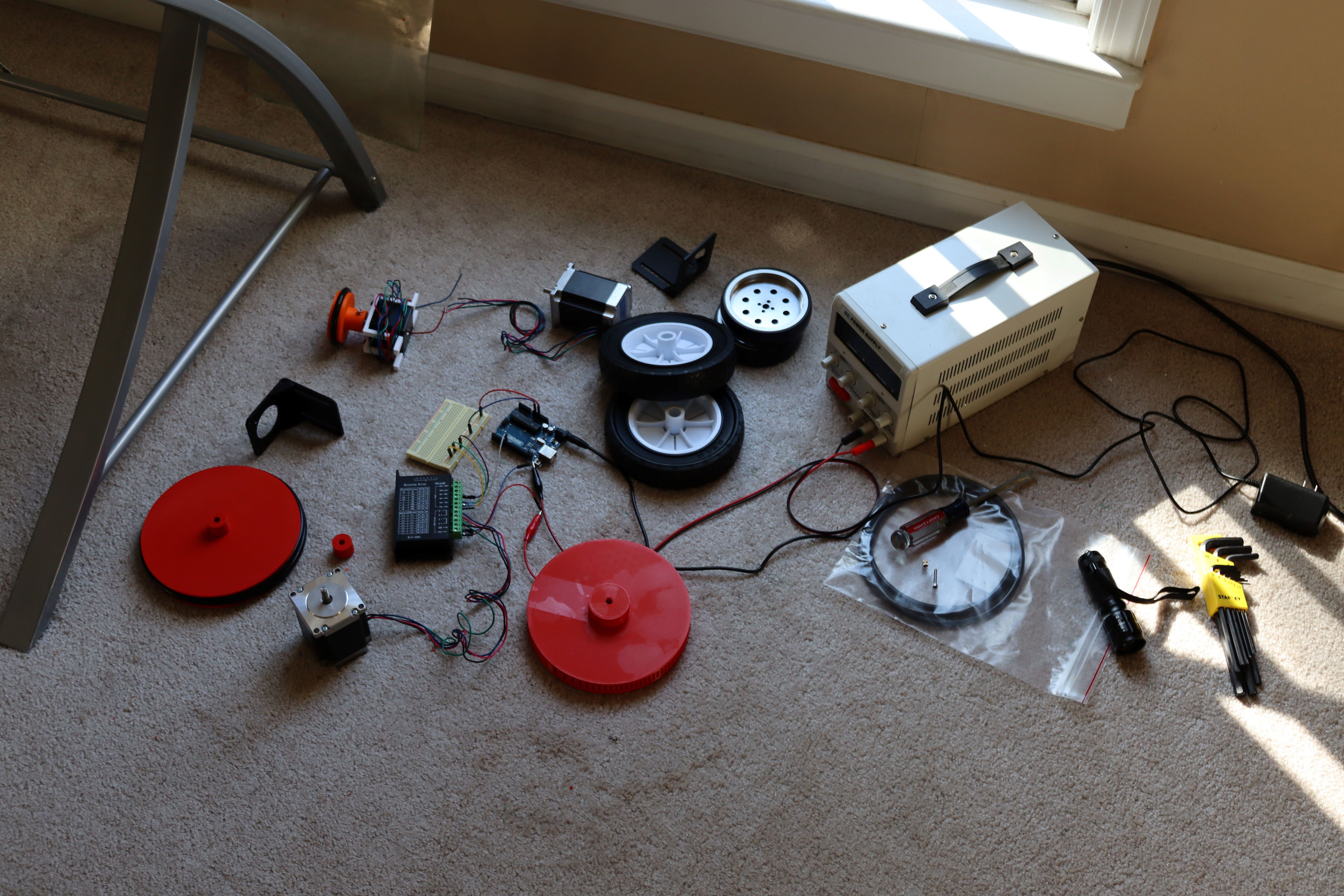
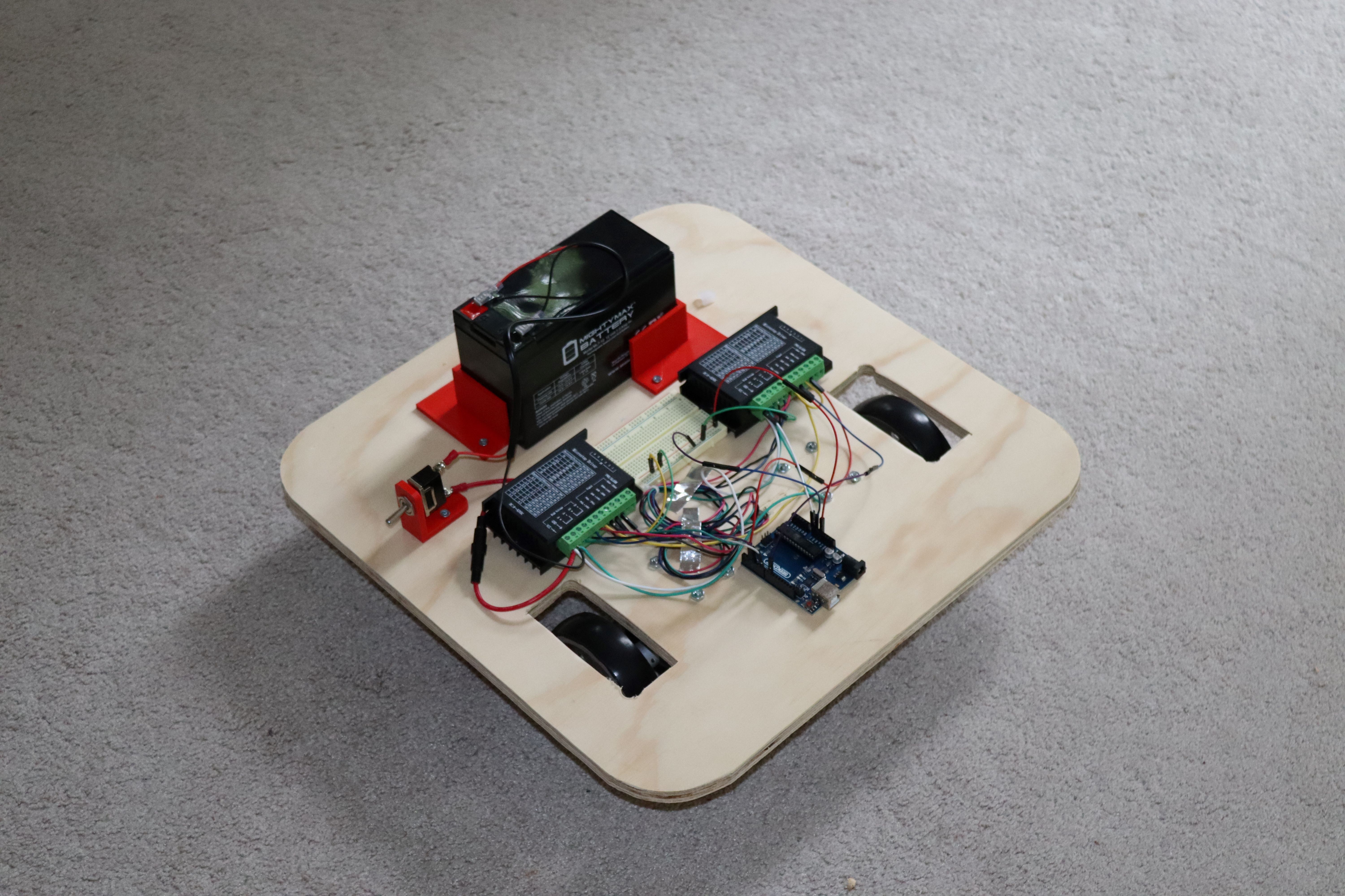
04/13/2023 at 16:46 • 0 commentsFor the first test, the component configuration looked like this:
![]()
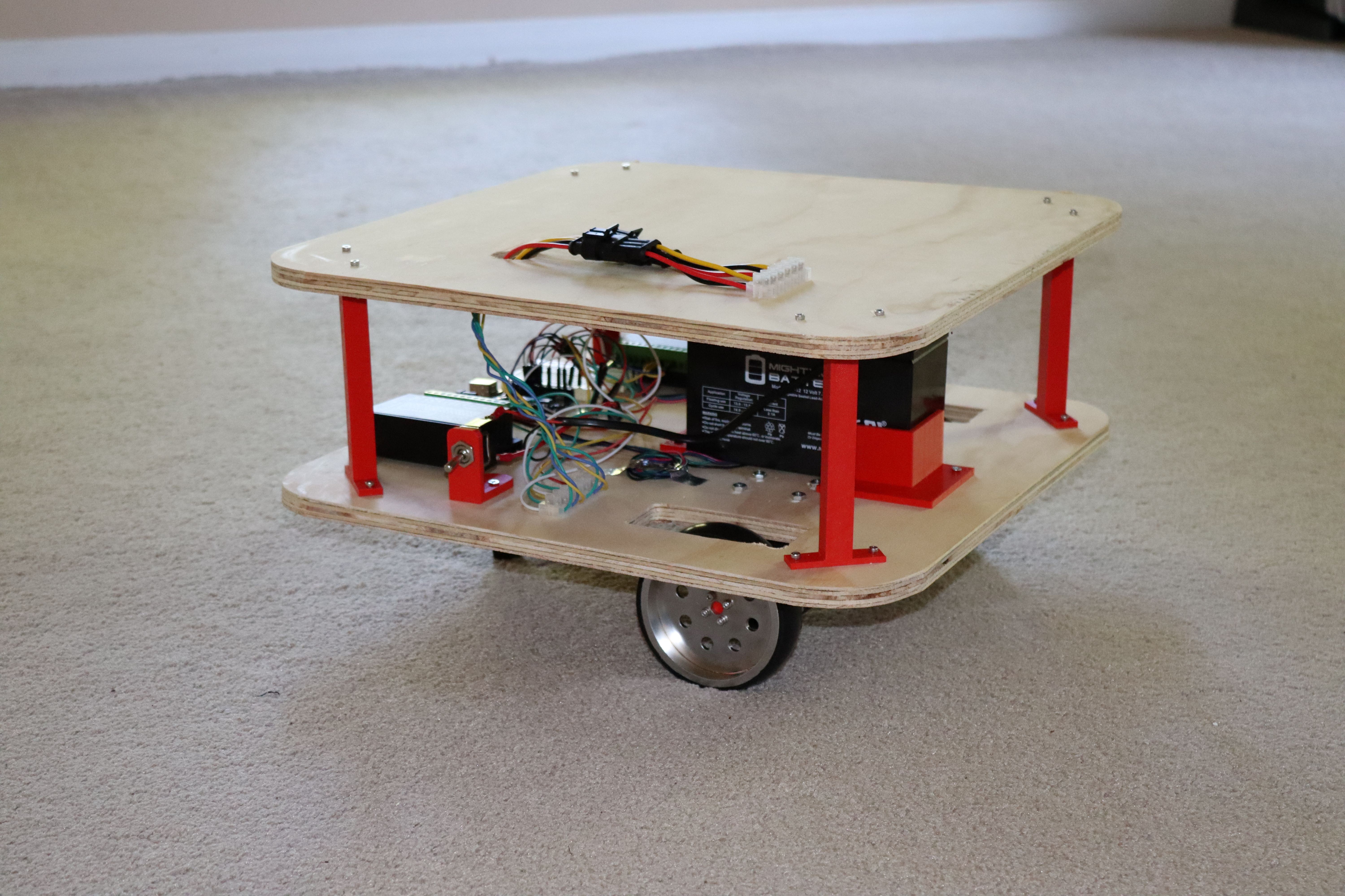
This works, but the 4.5 pound battery (over the caster wheel) creates a weight imbalance such that the front wheels tend to slip when making turns.
The solution is to move the battery closer to the drive wheels. This is actually consistent with Astro robot, where most of the weight is in the front with very little toward the cargo bay/caster wheel.
![]()
Sometimes it is easier to "see mistakes in action" rather than "planning for all possible faults in advance."
-
Base Construction
04/13/2023 at 13:23 • 0 commentsSo many choices--which wheels to actually use?
![]()
What size should the robot be? The Heathkit Hero robots (sold in the 1980's--I never had one of these) were 20 to 40 pounds; 40 pounds for the one with an arm. Astro, which can carry some load, weighs 20 pounds.
I cut an 18" square piece of 1/2" thick plywood for the floor. I used a quart size paint can for a template to round the corners.
![]()
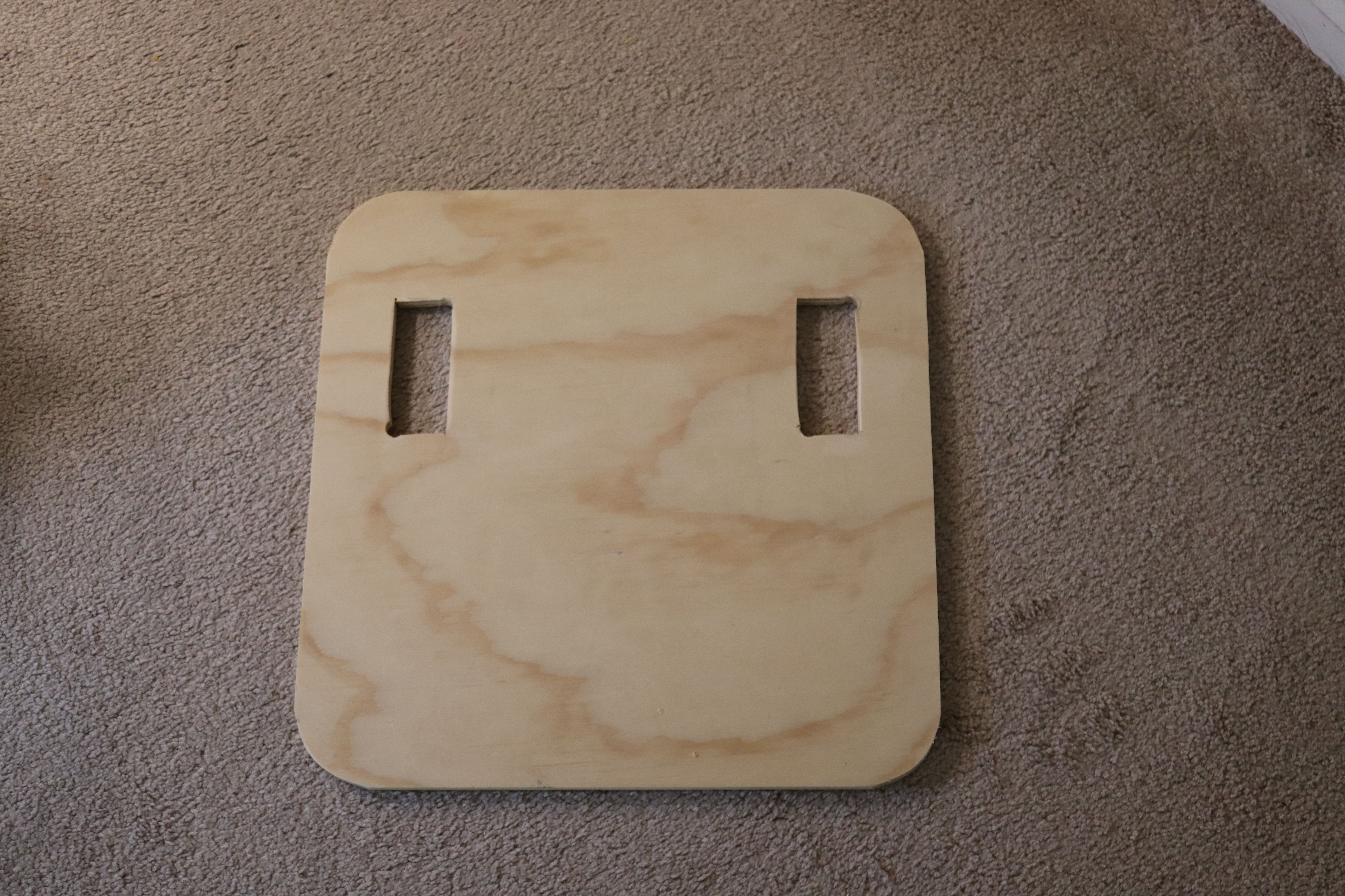
Next, I cut slots to allow a bit of room for wheels.
![]()
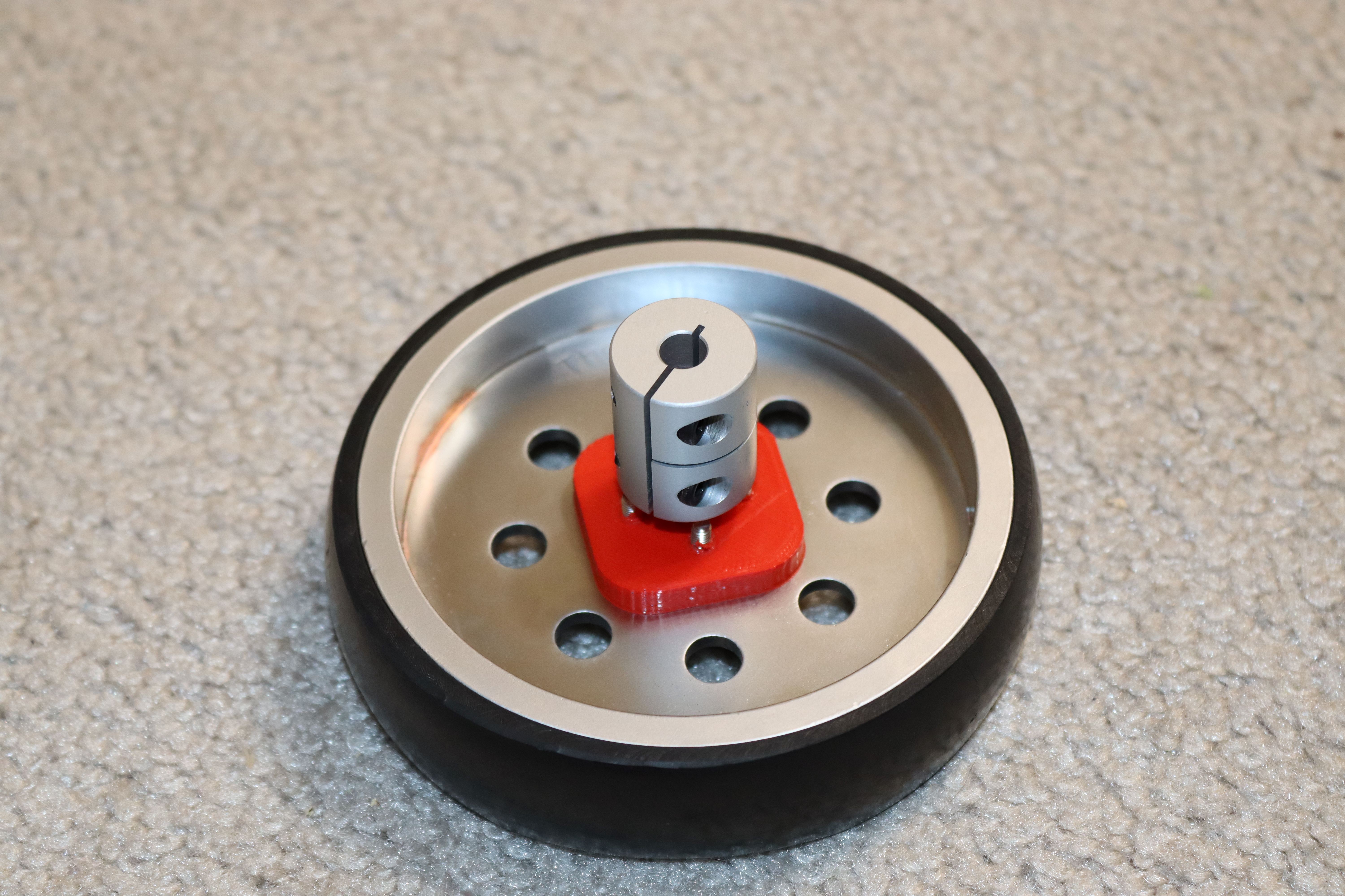
I 3d printed a wheel connector/shaft and secured it to the wheel using 3mm screws.
![]()
![]()
I attached an 8 mm to 6.35 mm shaft coupler (8 mm end) to the 3d printed shaft.
![]()
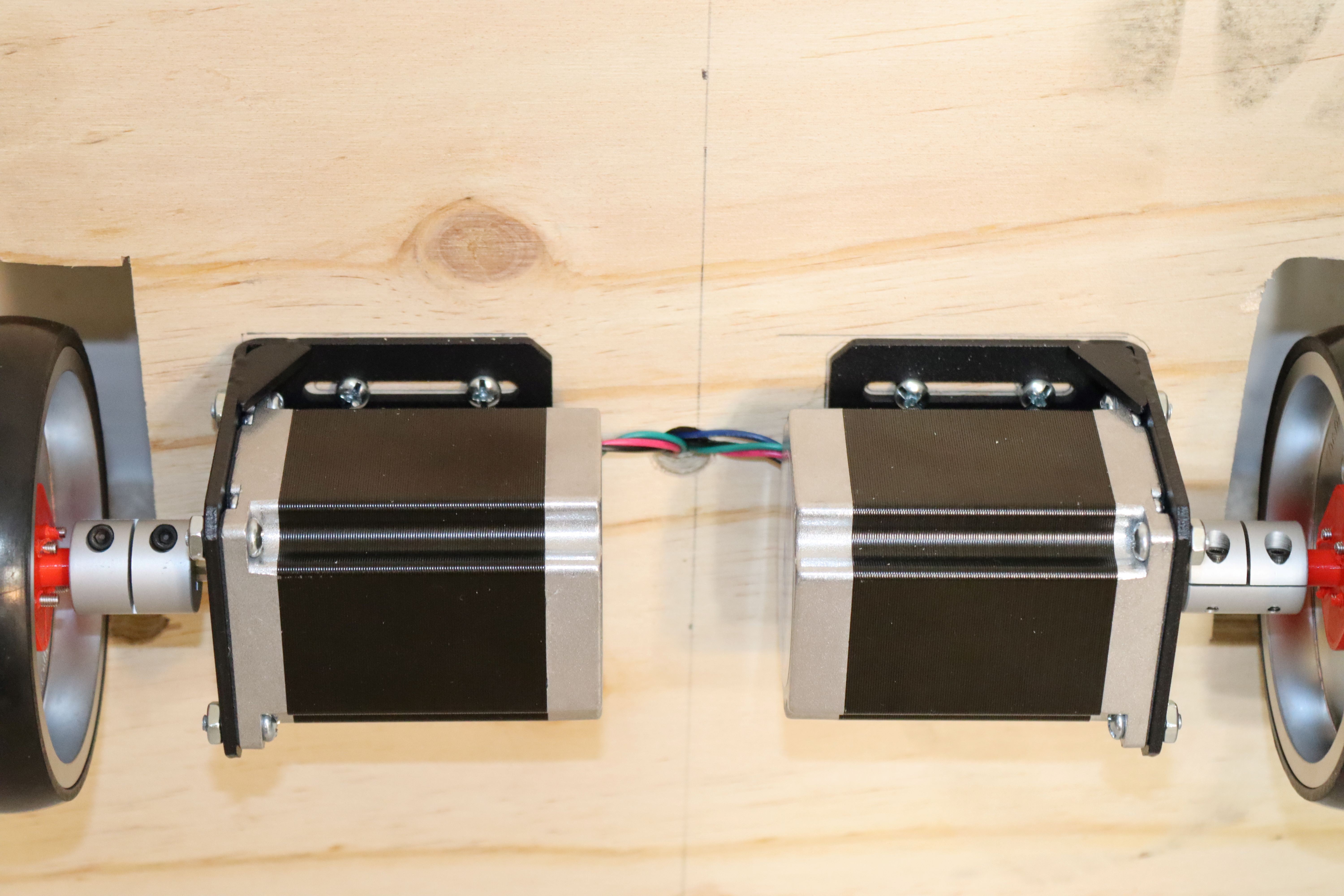
I bolted NEMA 23 brackets to the base.
![]()
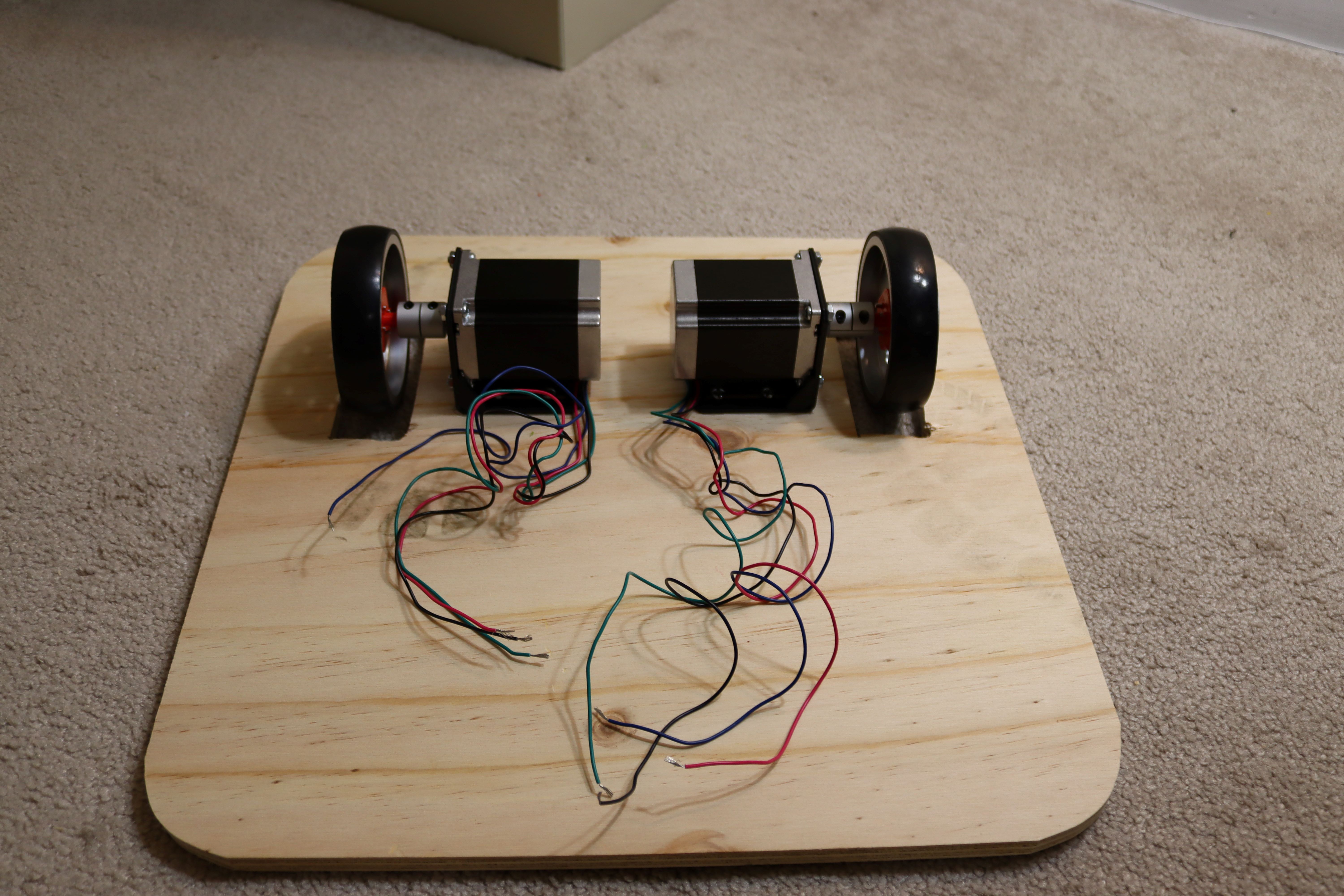
Next, I mounted a motor and wheel.
![]()
This was followed by the second wheel.
![]()
Next, I drilled a 1/2" hole through the plywood and inserted the motor wires.
![]()
Next, I added a 1" caster wheel to a 3d printed extender, then attached this to the rear of the platform.
![]()
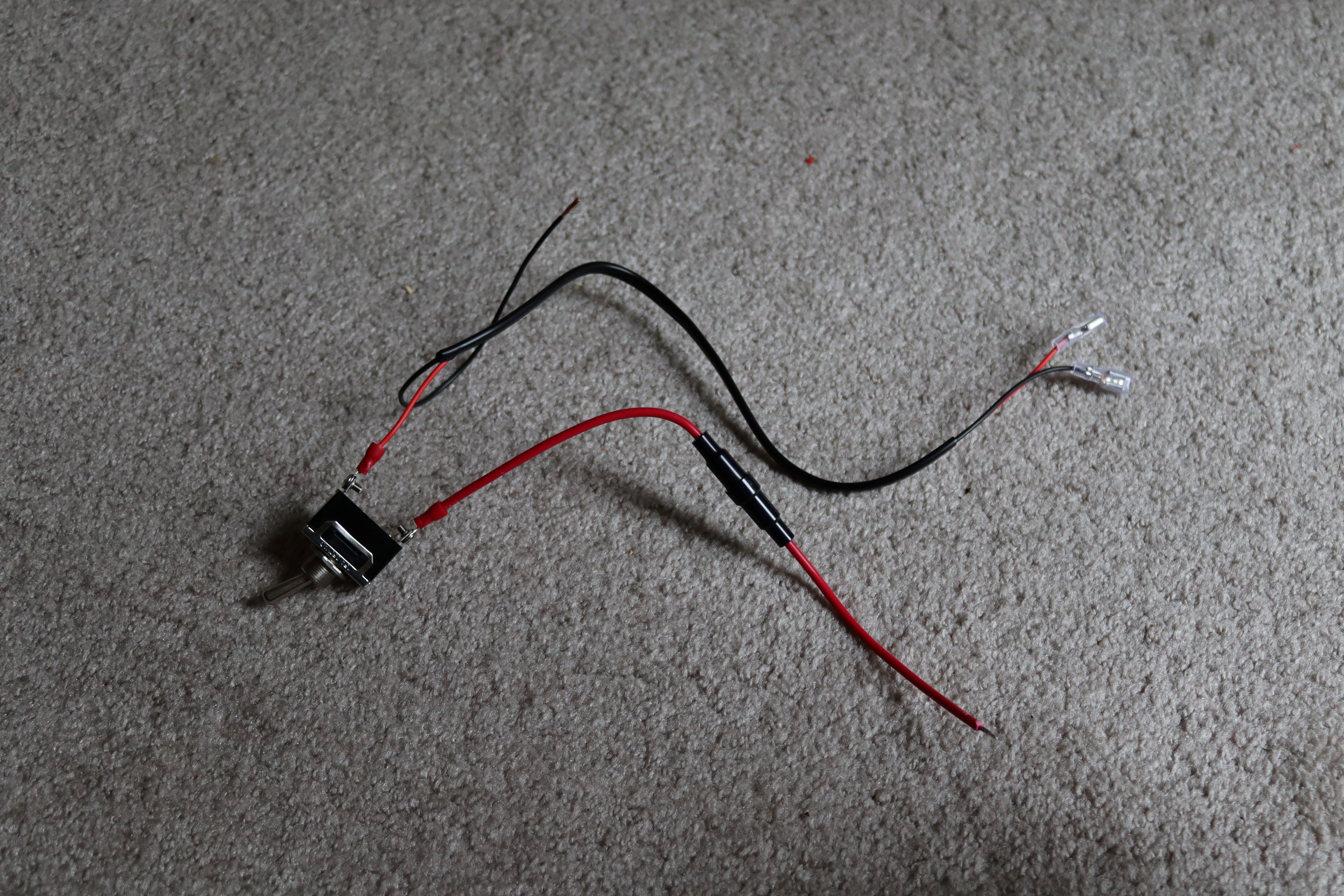
I added a 5 amp fuse and battery connectors to a toggle switch (on/off).
![]()
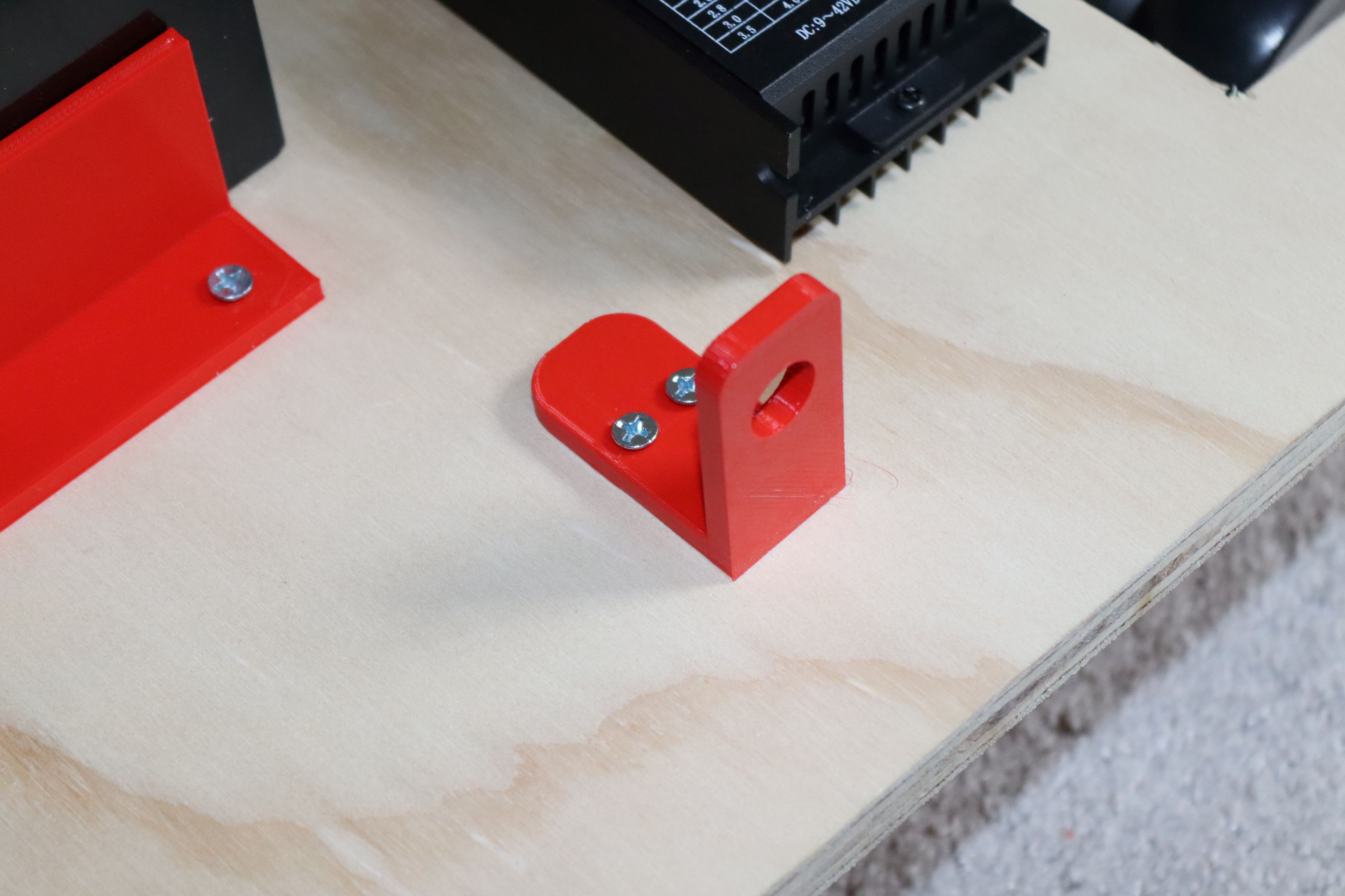
I mounted the 3d printed switch holder to the platform.
![]()
Next, I installed the switch.
![]()
This was followed by attaching the Arduino and driver boards to the plywood using Velcro. The battery was secured using 3d printed corners.
![]()
Control of the stepper motors is done through stepper motor drivers (less than ten dollars each).
![]()
These drivers require 12 volt power. The four stepper motor wires are connected to the A and B terminals. Positive 5 volts (from the Arduino) is connected to the plus terminals of the "signal" input. Note that this does not use ground as common.
The Arduino must provide a pulse (this controls the motor speed--shorter the pulse, faster the speed). The Arduino must also supply a high or low signal for motor direction. Last, but not absolutely required, is the enable signal. If you do nothing, the stepper motor will draw current and stay "locked" in the position where it last received a pulse. If enable is activated, the motor will not draw current and will freely turn.
Home Robot--What Can It Do?
Using existing robots for guidance, I plan to design and construct a household droid.