-
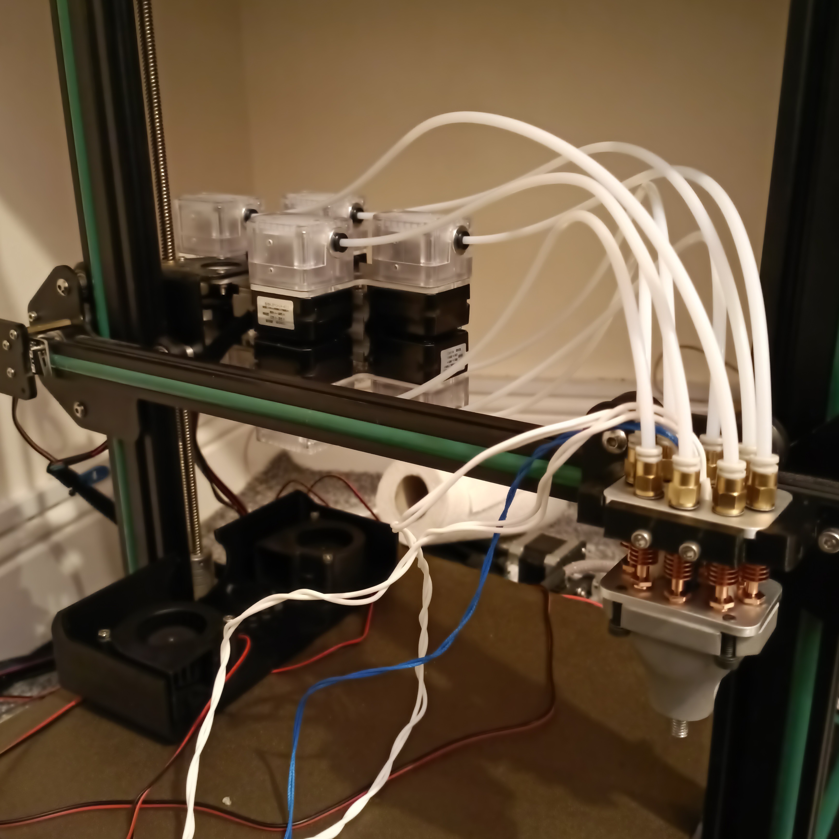
[A] Dryrun worked. Print powered down.
04/01/2024 at 15:21 • 0 commentsSo, instead of the "move fast and break things" approach that Me In January did, I took a more cautionary approach and did some dry-runs first. It's a good thing I did, because I caught issues like the G3 crash ahead of time and was able to increase my Y current to 900mA because it was skipping steps.
After a successful test-run of everything running except fillament through the extruders, I installed filament into them. The large gear on the DDEs are useful because I can see / feel if the filament has actually gone inside or if it caught on the bowdens. Seemed that the PETG understandably went through the system a lot easier with the c8or set to 224 degrees instead of the 188 I had originally set and used in the dryrun.
After getting the skin on my thumbs iirritated and peeling from all the high-torque scrolling of the gear, I used my handy M165 R to set the mix to A1 B1 and see that it was set correctly before then extruding perhaps 200mm of filament in. While this was happening, I took a flashlight to see if there were any obvious leaks and I didn't see any, which is a good sign at least.
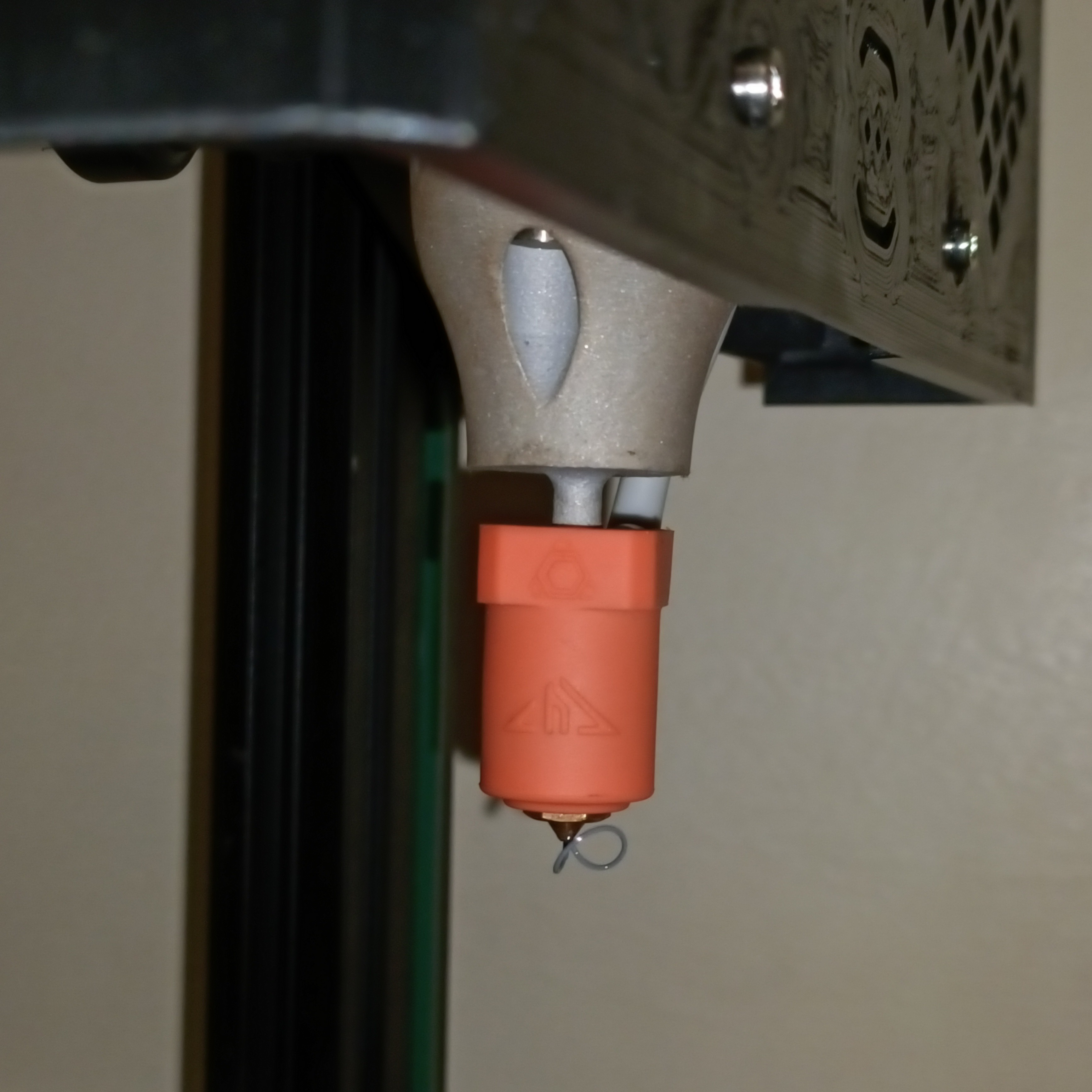
Whilst wondering if this filament was actually getting anywhere, I saw a whisp come out of the nozzle and ghasped.
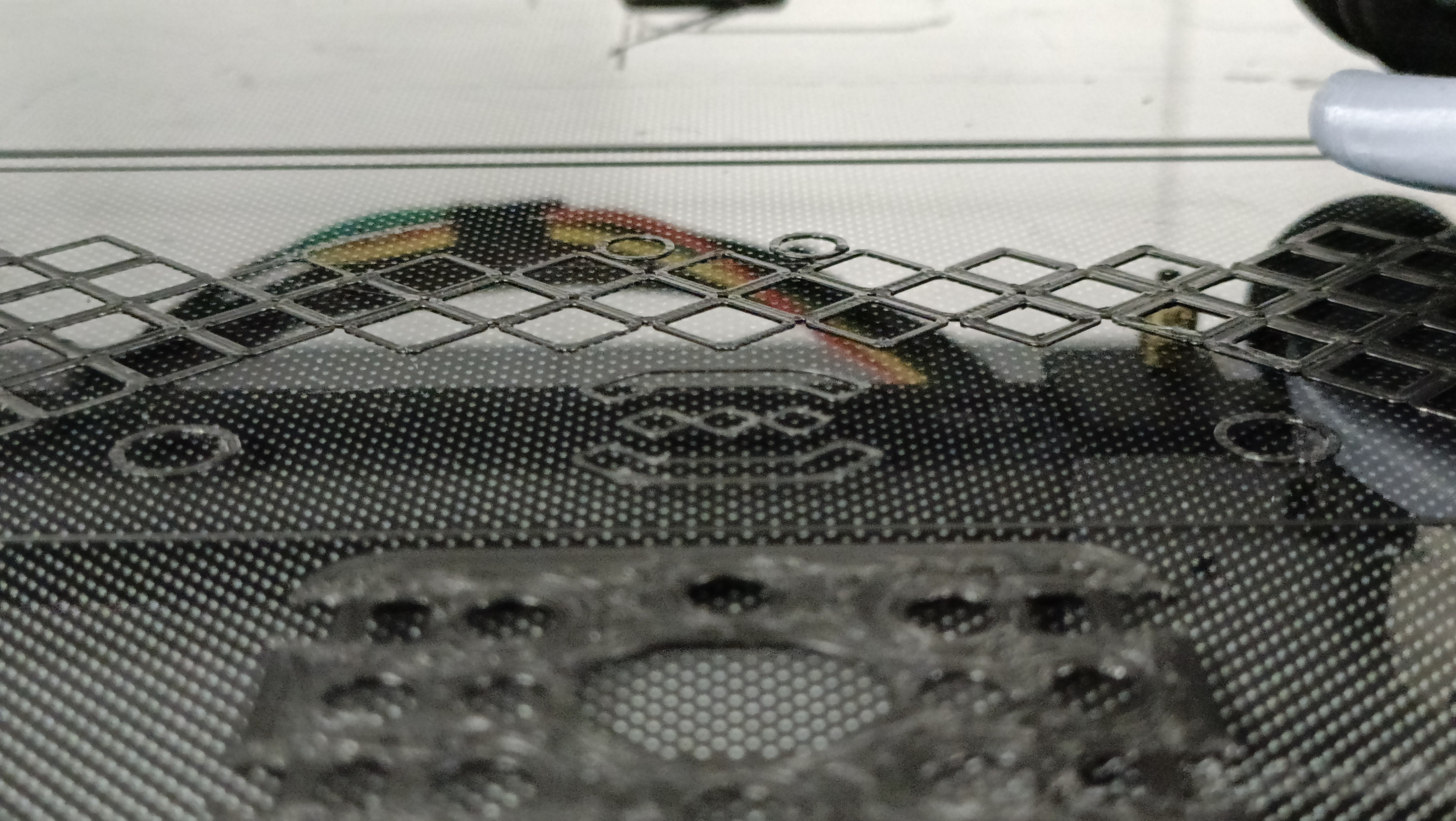
There's filament, and it's grey! I'm only extruding in White and Black PETG. Thus I changed the start-gcode to heat the Coaxial8or to 224C and pressed print.
Now this is where all the goodness ends, because my Z offset was wrong and so I was scraping on the bed. Whilst trying to increase the babysteps, the printer just turned off. This wasn't like the G3 crash where it would restart after a bit, because the PSU LED was off too! Whilst turning the printer off and on again brought power back and I was able to re-tram the bed, the power cut perhaps 1 second into the homing and heating procedure.
So I did the calculations and when I add:
- 140W Coaxial8or
- 115W CHC Pro
- 24V extruders with currents (in amps)
- X: 0.6
- Y: 0.9
- Z: 0.6
- E0-7: 0.45 x 8 = 3.6
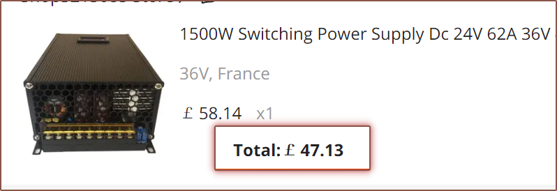
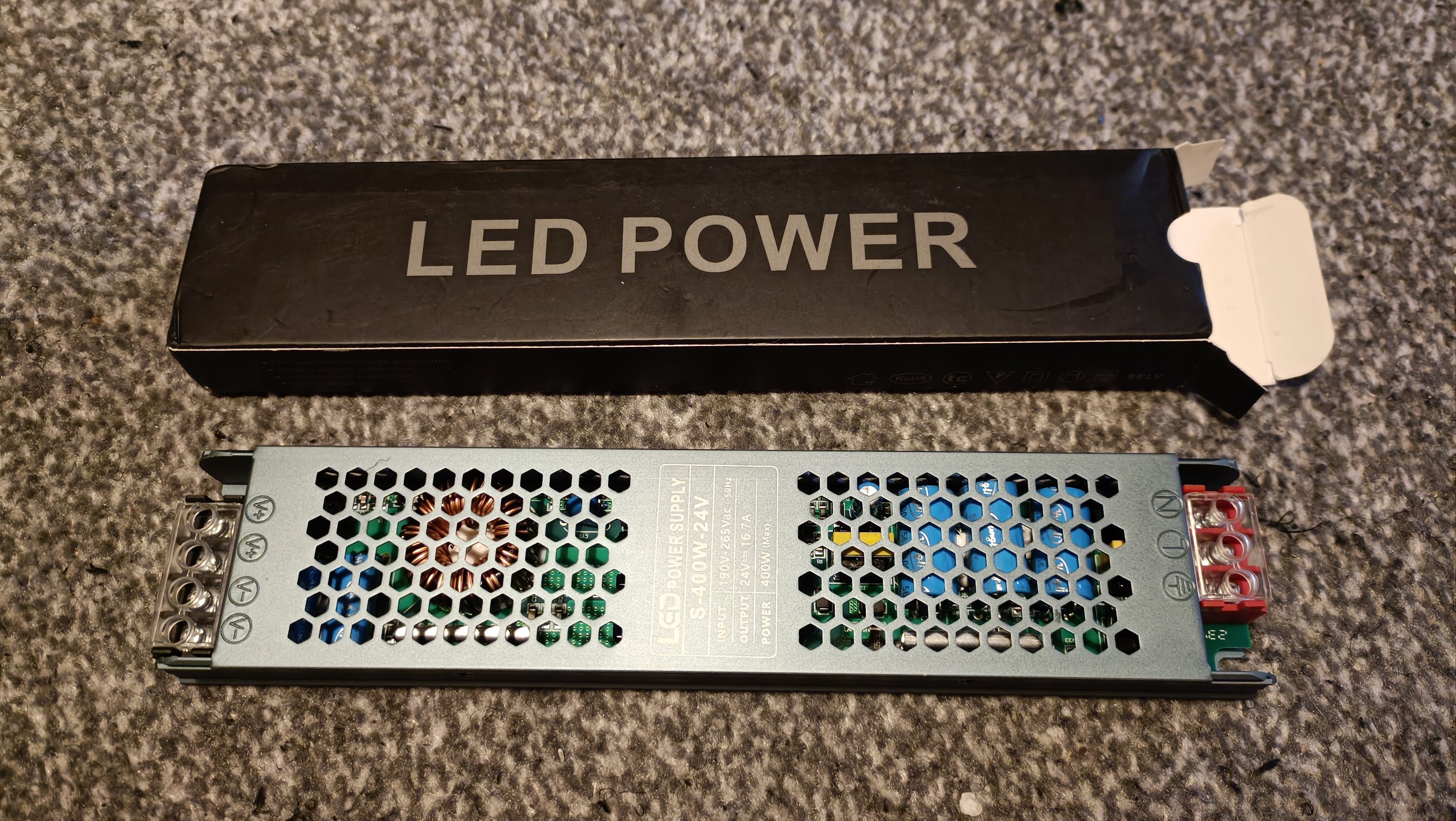
...I get 392W. Considering everything else would be probably another 15W, I've likely exceeded the overcurrent protection of my £6 PSU.
Look, I bought it because it was small, looked nice, was silent and would arrive fast (and £6 for all that sounded amazing). When I did the original calculations, I was getting maybe 80% utilisation, likely because of the lower initial motor current estimates of 0.6 for Y and 0.3 for each E.
This kinda makes a bit of sense because, during tests, I could hear the fans drop in frequency and the multimeter tested a shaky 20V value, most likely because the heaters are only toggled at a relatively low 7Hz from what I've heard in the Marlin discord.
I've still got my £60 (that I bought on sale for £11 off), 0 - 36V, 1.5KW PSU beside me so I guess I can install that, but first I need to lower the voltage to 24V or else I'll fry everything.
Just not a fan that the voltage and current adjustment are two tiny trimpots.
Surely this won't be the third power supply this project eats up. The good thing about this PSU is that it's got a current and voltage reading so I'd be able to spec the next one accordingly.
-
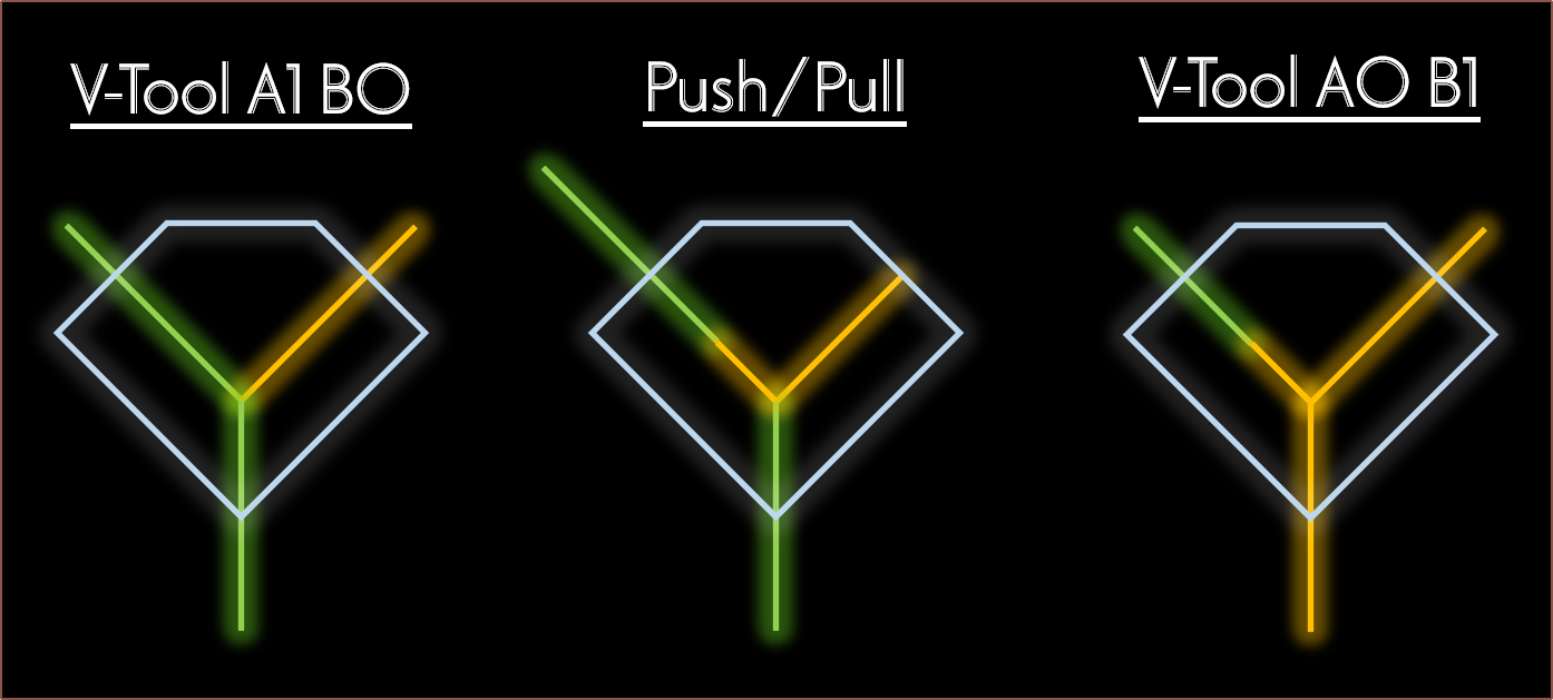
[C] Push/Pull V-Tools in Marlin
03/30/2024 at 17:09 • 0 commentsI've spent the past week implementing this feature I call push/pull toolchange.
It started when @heinz posted his findings with the Cetus2 nozzle and its strategy for fast toolchanges:
The shownotes of implementation went something like this:
- Day 1
- Write initial pseudocode
- Day 2
- Look inside tool_change(...)
- Write config modifications, looking at SWITCHING_TOOLHEAD for naming conventions
- Write more detailed pseudocode
- Try and understand what COLOR_A_MASK means
- Day 3
- Look at how the extruder directions are applied (and ask if there's any specific thing I'm supposed to do so that I don't break everything, since this is outside the mixing-related code.
- Look up what do { } while(0) does, and it seems to make sure if-blocks don't break things.
- Day 4
- Find out there's something called MIXER_AUTORETRACT_TOOL
- Understand a few other functions in mixing.h
- Create a pushpull type
- Day 5
- Turn off VSCode Cpp formatting so that it doesn't mess with the formatting that's already present
- discover "mix" and related functions, and enable them for push/pull
- Write initial implementation for pushpull in the mixing.h side of things, such as creating MIXER_PUSHPULL_TOOL instead of a colour in the pushpull type.
- Day 6 (today)
- Find out that there are bit-mask macros and use them to tidy up my code.
- Try, fail, try some more to create the new E_APPLY_DIR macro.
- Change get_extruder_bits(...) to e_dir(...), where the former gave the thing that asked for it the entire 8 bits wheras the latter is a boolean on if that specific extruder is inverted or not. This made the MIXER_STEPPER_LOOP easier.
- Allow pushpull to use the too_cold(...) function already in toolchange.cpp
- Get more errors that stem from how I implemented the E_APPLY_DIR macro, as well as Mixer::pushpull
- Finally get the E_APPLY_DIR macro to work by needing essentially a do { do { ... }while(0) }while(0)
- Add a definition of pushpull_t Mixer::pushpull into mixing.c
- Marlin compiles finally
- Fix errors when optionals in config.h are disabled
- Improve too-cold error message by adding an additional context message
- Everything seems to work except I'm not getting any directions
- Test to see that my bits are being set correctly
- Find out that I need to apply the stepper directions, and I can't do that from mixing.h
- Split the code so that the logic responsible for extruding was in toolchange.cpp.
- Extruders work but there are a few quickly-squashed bugs.
- Pull Request created.
Implementation estimate: 12 hours
Implementation time...
15 hours?
- Day 7 [Mar 31]
- Code cleanup to make it look minty fresh.
- Thought of a potential bug, confirmed and fixed it.
- When going from a A5 B5 C0 D0 to an A0 B0 C5 D5 mix, the push/pull length was wrong as I assumed it would just be 2x all the time
- Found out that G3 causes Marlin to crash and probably has something to do with the I and J values,
- Changing the HIJK mix characters to LMNO seems to fix it.
- Day 1
-
[M][T] Coaxial8... 4 A Budget?
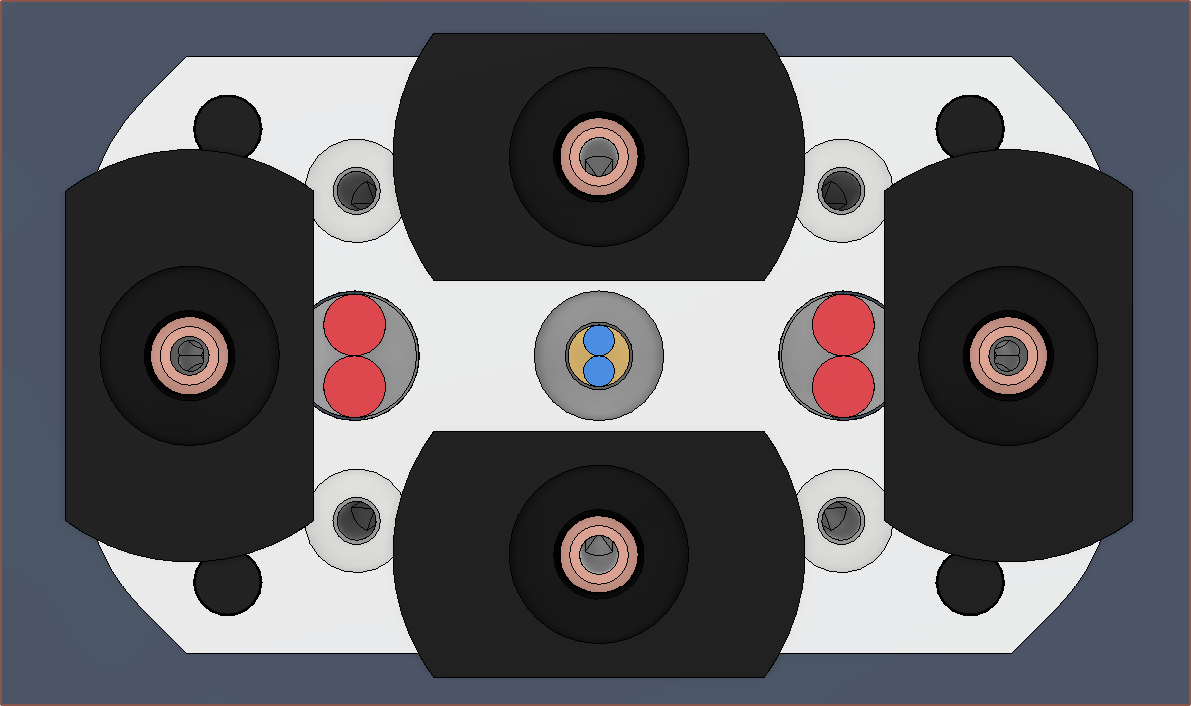
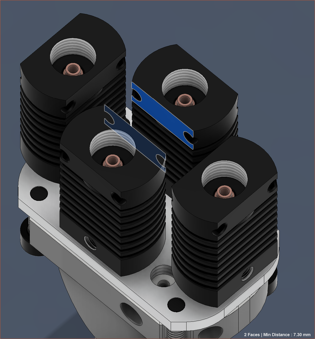
03/25/2024 at 06:28 • 0 commentsI just got this quick idea to see if classic CR-10-style heatsinks would fit such that it can still be easily mounted onto a CR-10 / Ender3 whilst using the 2x M3 bolt mounting points (and not having to print a holder). This is because I was thinking of the Coaxial8or from a finance perspective.
6 inputs?
The main question I expect to get is "Why 8 and not 6 inputs?" and one of the reasons is that, financially speaking, the difference is about a £30 upgrade. The cheapest option to run a 9-axis Marlin configuration is an MKS Monster8 + BTT EXP MOT and it's probably cheaper to buy 10pcs couplers than 6 individual ones, thus the only difference in price is 2 of the following:
- Nema 17
- Extruder
- Stepper driver
- Dragon heatbreak
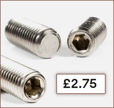
Additionally, there exists "flat point" grub screws. 10pcs M6x6 only costs £2.75. I'm assuming that if the heatblock is first filled with cleaning filament, the unused channels stay inert and don't clog, allowing for the possibility to upgrade to the full 8 inputs in the future.
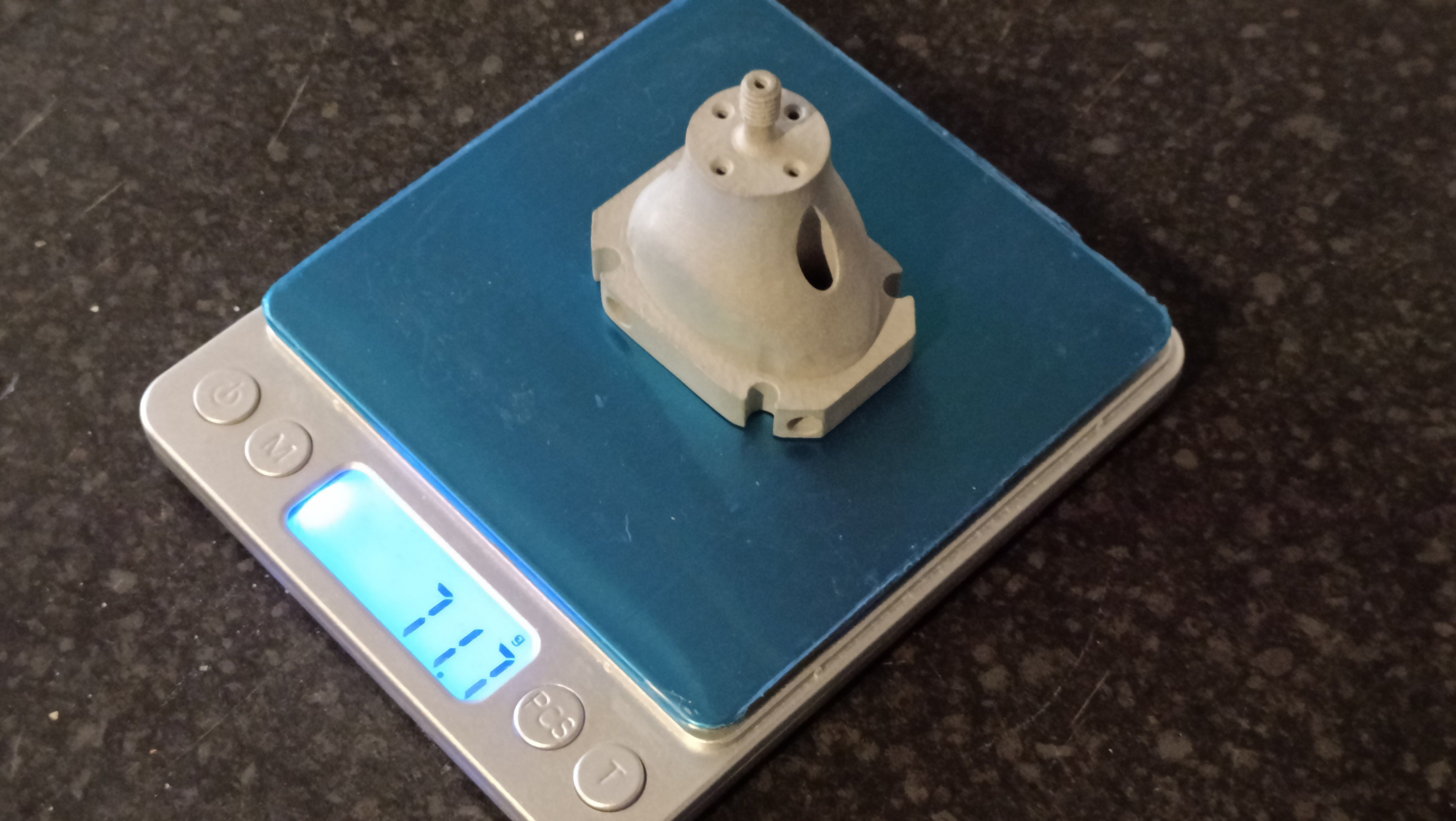
For the aluminium print itself, the auto-quote is $46 and I doubt the ~5mm shavings in the X and Z bounding box would account for much, since it seems that the minimum PCBWay cost is around $38-40.
4 inputs?
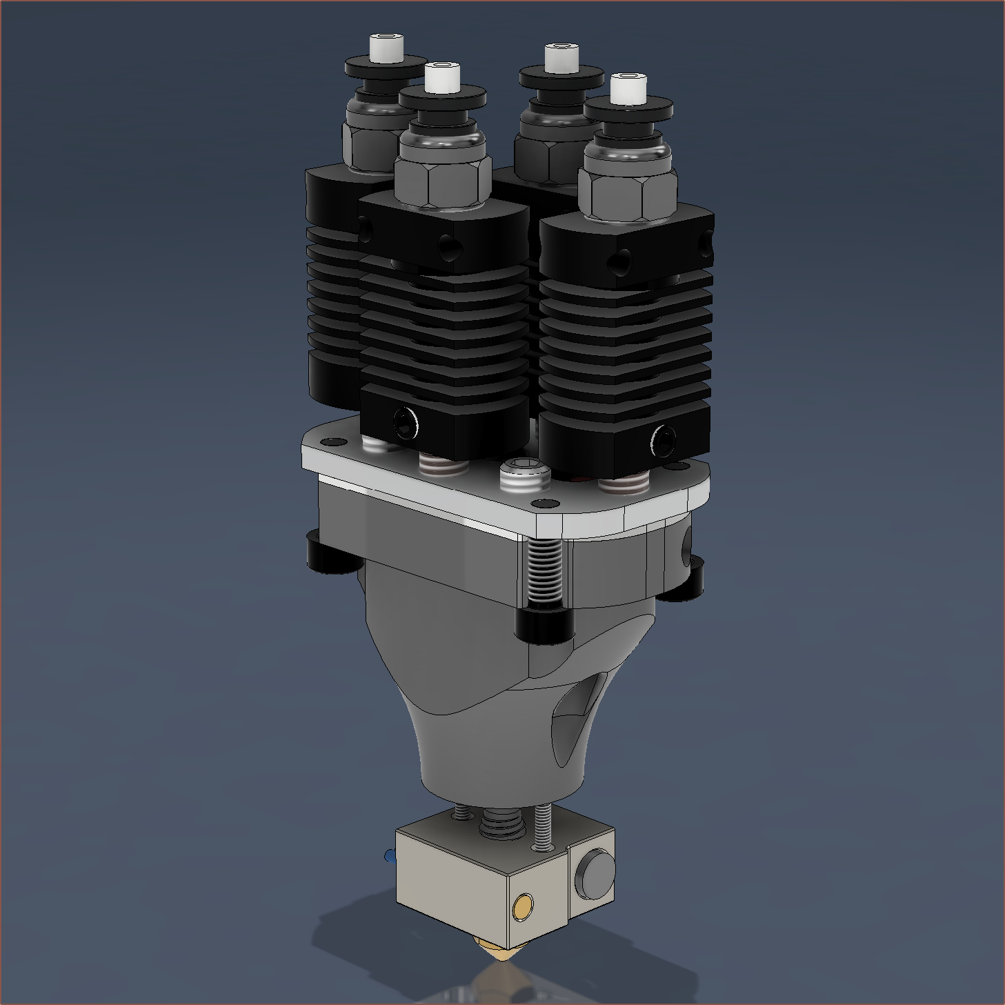
The financials (and ease of set-up) for 4 input make more sense, as the heatsinks are cheaper, all the drivers fit on a single board and could even be a pseudo-drop-in replacement for anyone using a Zonestar 4-in 3D printer / Prusa MMU1.
A 2x M3x35 bolts would be needed to mount the hotend, and a 7mm spacer would need to be bought or printed:
The result is what I'm currently going to call the Coaxial8-4AB:
I believe it might be easier to ensure a sufficiently tight seal with these normal heatbreaks because of the PTFE gasket.
-
[E1][X][M] Heating Tests and Coaxial8or R1 (Revision 1)
03/20/2024 at 20:42 • 0 comments- Me In The Past, looking at the CAD a day or two before ordering it:
- I've trimmed as much as I can. It's unlikely that this heatblock could use any less material, and if it's possible, I'd like to see it
- Me Today:
- Me In The Past, what lies!
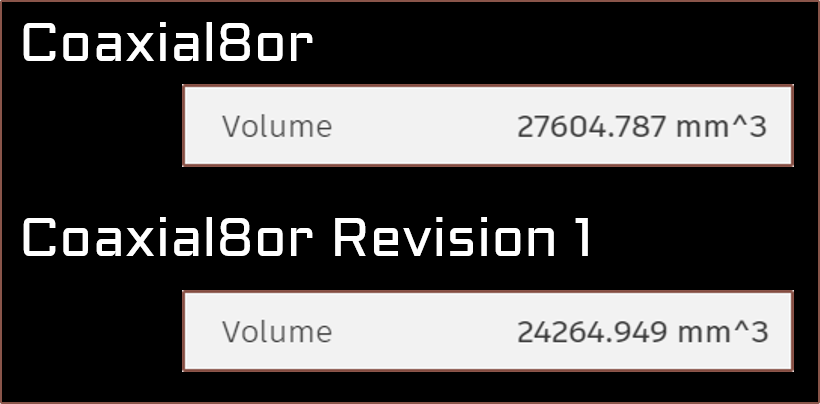
A 12% mass reduction, finally getting a mass : 8-volcano-blocks ratio of under 1. It's now 0.955 : 1. Just like how the iPhone rumour mill will switch right to the iPhone N+1 leaks on the launch of the iPhone N, I've decided that I am indeed going to spend "15 minutes" to implement the tweaks I've had in my mind. The urge to do so stemmed from the fact that I spent 90 minutes this morning switching out the partially melted hotend holder with a fresh one (still in PLA unfortunately) because the "chamber fan" didn't turn on like it was supposed to when I did a PID of the Coaxial8or.
Let's rewind a bit.
Heating tests
So the heating test with the CHC Pro was simple enough actually. I first heated it up just so that I could remove the other components currently attached to it and then attach it to the Coaxial8or. Surprisingly, not a lot of torque is applied through to the CHC Pro when tightening the nozzle, suggesting that I might still have somewhat easier nozzle changes than a usual hotend setup.
Then I found out that I can't actually set the temperature of the coaxial8or, which was on Heater1 (instead of Heater0 for the machined coaxial hotend back in Jan/Feb). I immediately decided to pivot and use the provisions coded into Marlin for the chamber heater. This is what I've done inside the pins.h of the Octopus:
//
// Heaters / Fans
//
#define HEATER_CHAMBER_PIN   PA1
#define HEATER_0_PIN         PA2   // Heater0
#define HEATER_BED_PIN       PA3   // Hotbed (default PA1)
I also tried (and failed) to set an auto chamber fan. The chamber fan doesn't come on at all, and there's a separate CHAMBER_FAN thing that, when configured to the below, turns on if the set temperature is >=10 degrees and turns off immediately otherwise. It also causes spam in the serial port.
#define CHAMBER_FAN
#if ENABLED(CHAMBER_FAN)
    #define CHAMBER_FAN_INDEX     4
    #define CHAMBER_FAN_MODE      0
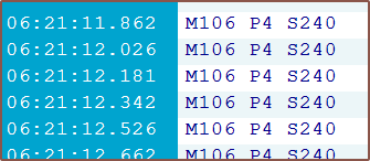
Maybe 7 times a second? Long story short, the MPC autotune of the CHC Pro was eventless, but the PID tune of the Coaxial8or left the hotend assembly wobbly and the M3x45mm bolts hot to the touch.
As for temp stats:
- C8or 160C and CHC unpowered = CHC at 131C
- C8or 160C and CHC 210C = CHC running at 50% power and temperature oscillations for the CHC are +0.0 and -0.2 degrees.
- CHC can also easily reach 210C when the C8or is unpowered, suggesting that I'm not losing too much thermal energy through the connection at the moment.
Part cooling
Also to mention, the part cooling fan does seem to direct air closer to straight-down. I'm hoping to make a duct that can disperse this airflow (instead of usual designs that try and force as much as possible through the nozzle) as I believe that it would better cool the part. My hypothesis is that, since the nozzle usually moves away from the hot material relatively fast, focusing all the cooling on that one location isn't a good idea. Additionally, from doing those thermal simulations for the unibody coaxial hotend, I've found out that a 2x increase in air speed doesn't translate much into the amount of temperature reduction of a heated body.
Heatsink cooling
Before I swapped the hotend holder, I wanted to see if the cooling would've actually been adequate to keep temps under control. I enabled the CHAMBER_FAN and set the temp to 160C for 15 minutes (basically where I got the "temp stats" seen further up in the log) and the mounting bolts were cool so things seemed good enough for me.
Swapping the hotend holder
So the warping wasn't actually that bad, but I only found out once I had actually taken the holder off. Cue the next 60 minutes of me essentially dissassembling and reassembling everything, because I still need to see though the couplers to know what resultant force vectors to apply to get the heatsinks to slide into the couplers.
The first revision of the Coaxial8or
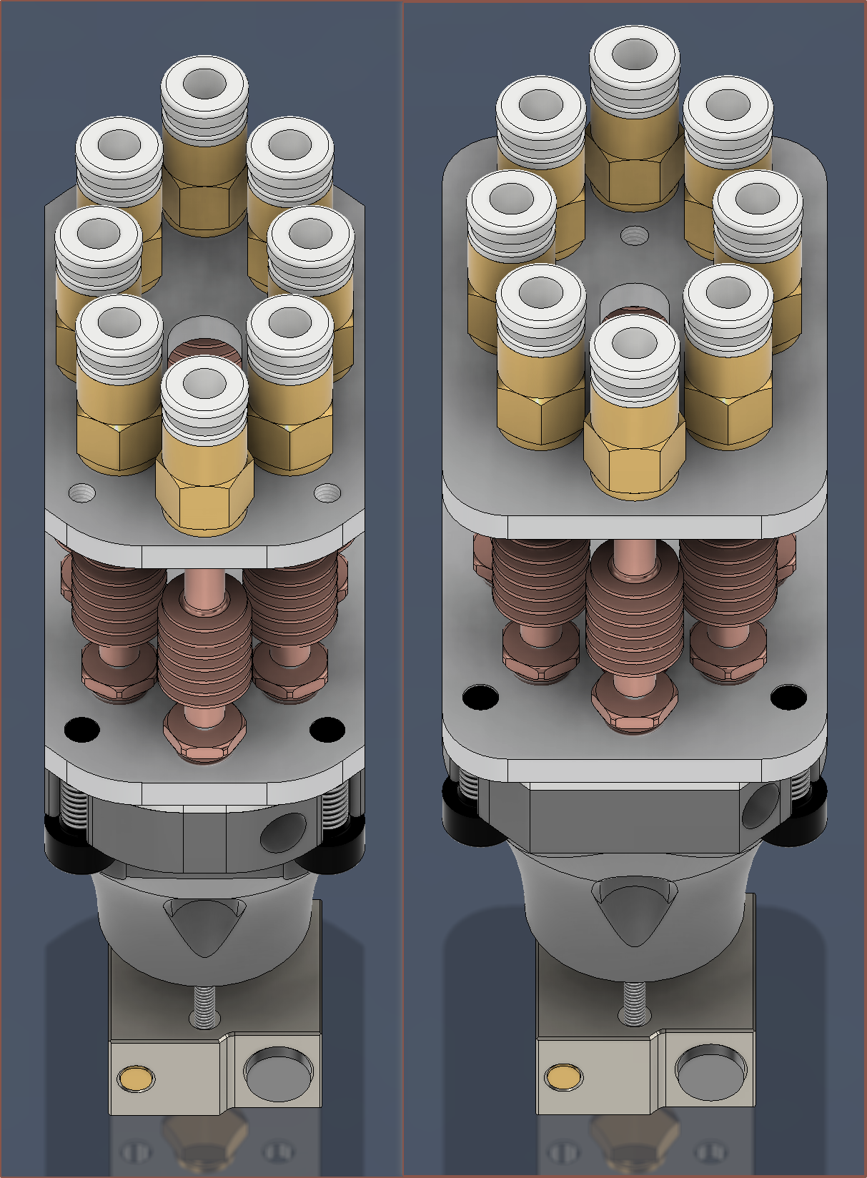
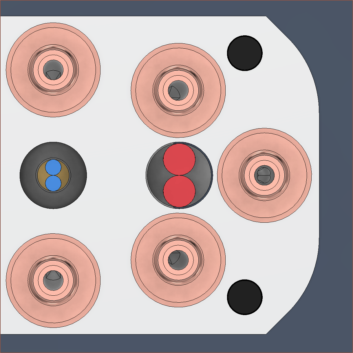
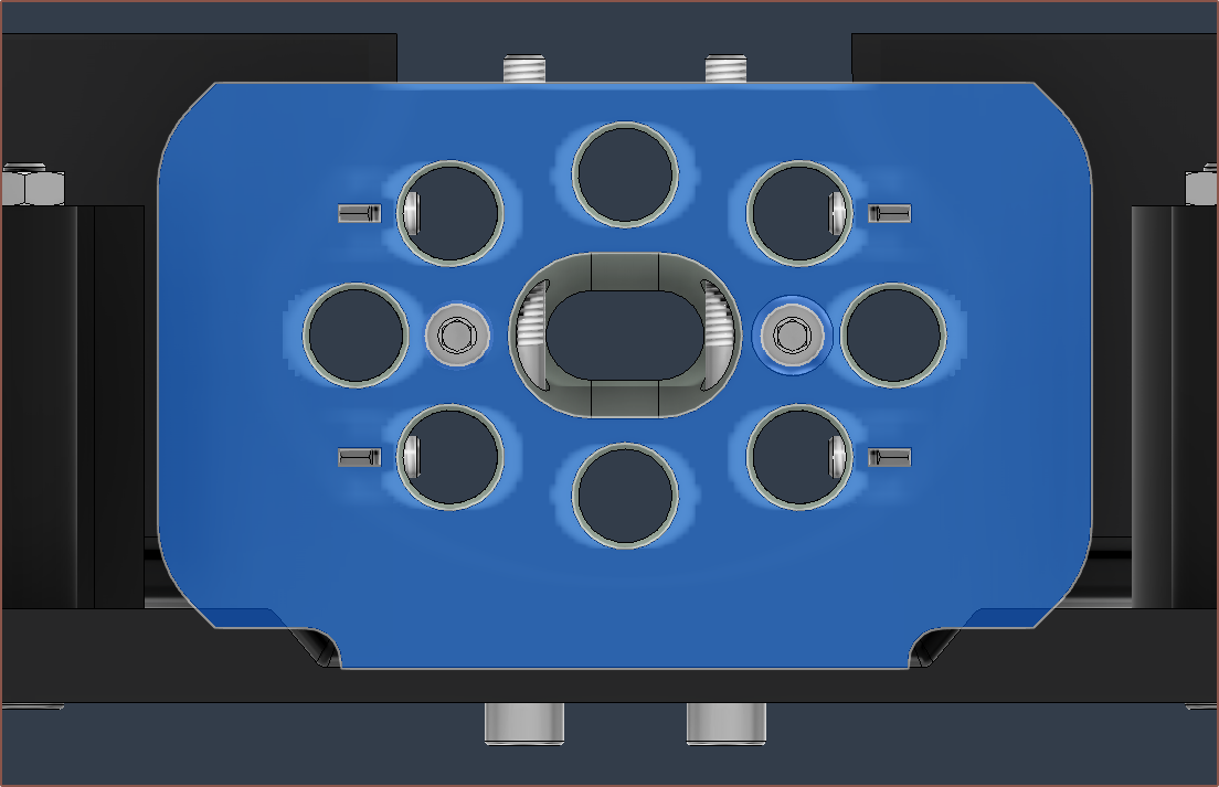
The new one is on the left. Also notice how I've been able to use filleted chamfers on the plates too, as I've swapped what edge gets filleted on the heatblock and it no longer would conflict aesthetically. This filleted chamfer orientation is the same as the Coaxial8or cover, providing design consistency. When I finally finished with the CAD, I was thinking that it looked quite slim considering that the dimensions have only changed from 35*49mm to 30*50mm (notice the divisibility of 7 and 10 respectively as it's one of those nice round numbers that nobody but the engineer (aka myself) would care about). It's only when I got this screen snip that I could certified say that it was notably thinner. At the same time though, the minimum distance between inputs has actually increased (to 11.3mm), meaning that I could use 10mm diameter couplers if desired.
The thinness is important, since I'm trying as hard as possible to preserve a 300*300*300mm print area on my CR600s. Without modifications, a CR-10 or Ender3 would presumably lose only 9mm from the Y axis with this hotend compared to the default hotend (which is 12mm thick).
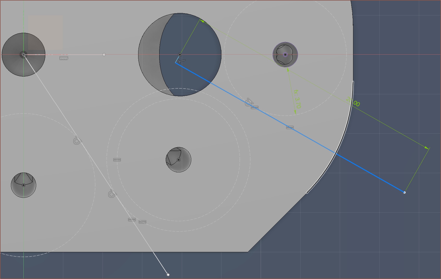
I thought it was game over when I couldn't find space for the M4 clamp plates, but after a break, I quickly realised that I could just delete a 135-degree constraint so that I could move the grub screw hole out of the way.
I've set the centre-offset (the small line on that blue L) to 0.75mm. In other words, the thread line is 0.75mm off from the centre of the cartridge. I've also now gone with 4 M3's on the outside for the coupler plate, and that's so that I can print 2 halves of a hotend holder and screw them on with an allen key after aligning the heatsinks to the couplers.
I've deleted all the really small triangles that I had made in the negative mould geometry:
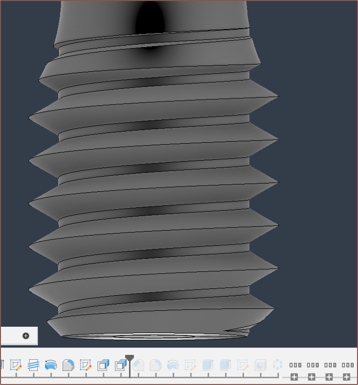
I've sharpened the printed M6 thread since the thread that was printed seemed a bit lacking. Ideally, I'd actually make a custom thread that has 45 degree angles instead of the 32 degrees seen here for a traditional M6:
I also want to mention that I got rid of the legacy Unibody Coaxial Hotend geometry (a.k.a. the heatsink part) from the file.
Oh, right, speaking of heatsinks, I've made sure that there's enough space so that they can be taken out without having to unscew any heatsinks. In the currently-printed design, the heatsink covers the heater cartridges by 1 entire millimetre, stopping it from being taken out.
Conclusions
So there you have it, a new design that actually took 3.5 hours to generate, not "15 minutes" as I claimed.
I was just worried that, if I needed to increase the spacing of the coaxialiser center, I would essentially have to be trying to do a respin of everything just because of a single change. Despite me worrying about it all week, I still haven't increased the spacing from 0.95mm, as I want to test out the current one before I increase it. I'm just somewhat glad that, if I desire to get the Coaxial8or respun, it's not a ClickOnce change. Still though, I doubt I would've actually needed a physical model to apply the changes that I've done today.
Trivia
I like how I finished the new design on the 7th save, resulting in "Coaxial8or r1 v8":
As you may also notice, I haven't added a fillet to the main body of the heatblock, and that's because everything was already so smooth and flowing that I thought that the sharp edge in the surface would make it look sleeker and less bottle-like, similar to the surface designs on cars.
[Mar 22]
On the day I ordered the current Coaxial8or print, and today, I was thinking about Mark Rober, a youtuber, talking about what he coins the "Super Mario Effect" (and mentioned by Forbes). The main takeaway is that, with no penalties or drawbacks, participants tried nearly 2.5x more attempts and got a 16% better result.
I found that interesting, but moreso was the flipped around argument; even with a penalty and, as a result, attempting 2.5X less, the other participants were only 16% away from a more optimal result. This gave me the confidence to finally order the hotend, knowing that "well I'm probably within 16% of the optimal solution".
Today, I was able to get the depth down to 29mm and mass to 63.5g. To sound a bit like Apple, the resulting design is a 17.4% reduction in depth and a 14.7% reduction in volume from the current "r0" design. I've broken the sub 24,000mm^3 barrier and now the heatblock sits at 23,555mm^3. It also means that I've now cut the Y offset by a round 3 milllimetres.
- Me In The Past, looking at the CAD a day or two before ordering it:
-
[M][A] Successful hotend holder and extruders installed
03/15/2024 at 22:42 • 0 commentsExtruders
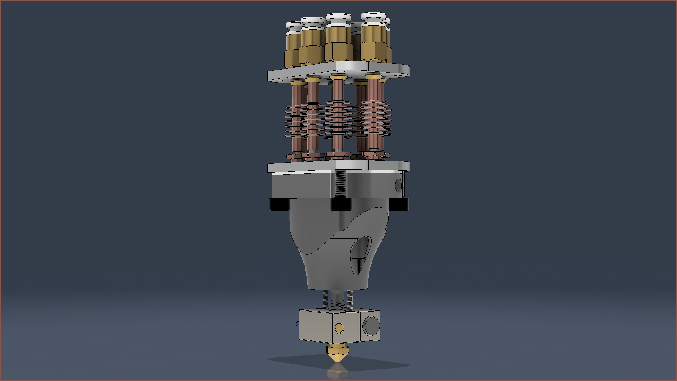
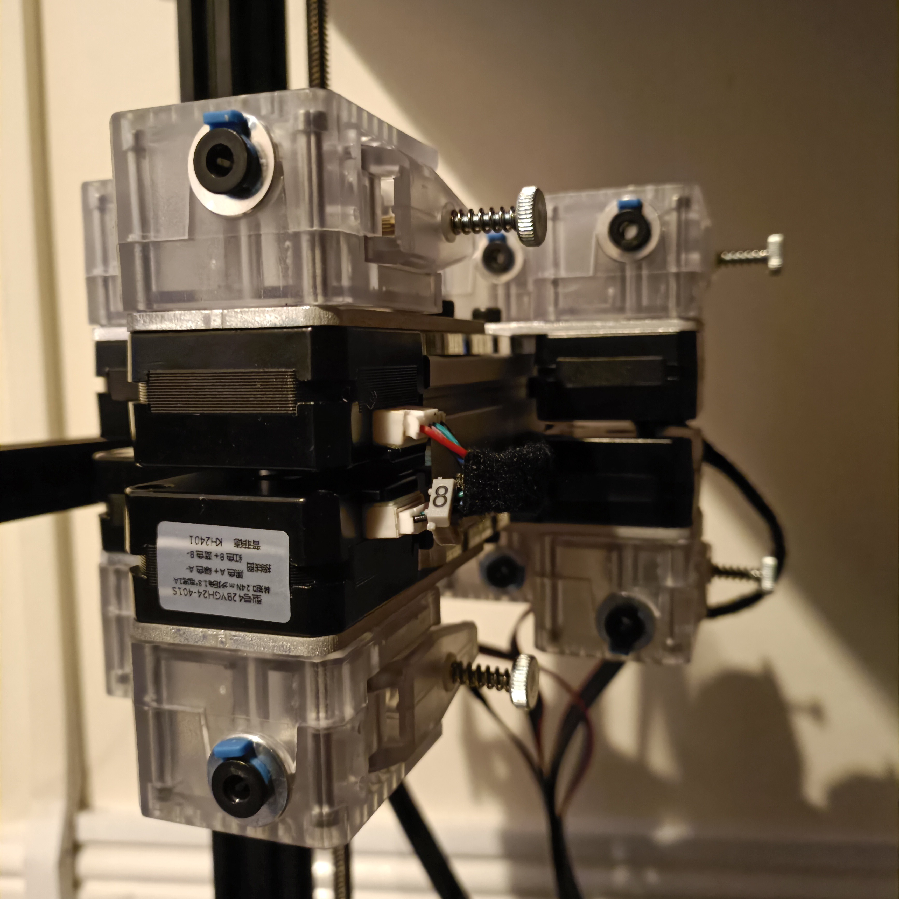
Coaxial-eight-or... So I should mention some thing if anyone is planning to use a 3mm mounting plate and 35mm bolts with these DDE extruders:
- The holes that they go into are 5.5mm for the bolt cap, and unlike the ones that come with the extruder which is 5mm, the bolts I got in the mail are 5.35mm meaning that the tolerancese are tight and thus need more effort to screw in. The benefit is that they're unlikely to unscrew due to vibrations.
- I needed to use M3 washers (that my university happened to have) to have enough clearance between the end of the bolts and the thread depth of the motors. The washers are 0.48mm.
Other than that, they seem rather nice:
- They're translucent so I can see things like mounting bolt depth, if the motor gear is turning, how deep the bowden tube is...
- There's a small cutout to be able to pull the bowden coupler as far forward as possible. It move slightly inwards when pushing the bowden tube in.
- Perhaps it's the thinner motors having less unpowered torque, but I find that the metal gear is both easier and more comfortable to spin than the plastic gear.
- It's much easier feeding filament in compared to the black ones I had.
- It seems that the perfect height for the motor gears is such that the bottom of the gear coincides with the bottom of the D shaft section of the motor.
Holder
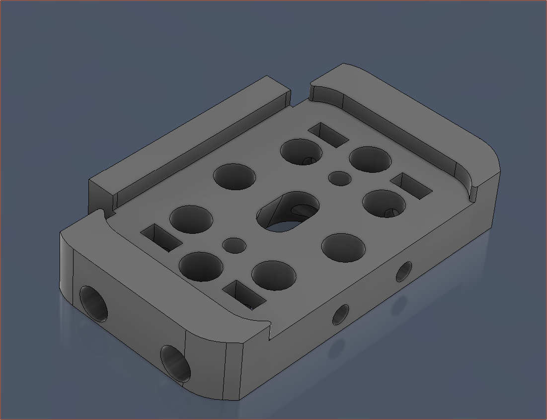
So I had the hypothesis that it was the holes in the hotend holder that was preventing me from just aligning the heatsinks by feel, and so I made a through hole of the clearance holes used to allow the M6 threads to stick out from the other side of the coupler plate. The good news is that it worked and the grub solution seemed to work nicely (I only needed to softly tighten them for the assembly to stay fixed in place. The bad news is that I did all this in "Isolate" mode and didn't check for intersections:
It worked, but it was not ideal, so I did a respin with the extras cut out.
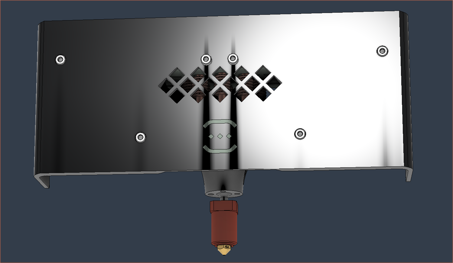
I modelled those side-wall, locking screw holes to be 6mm for the M3 bolt head, but it was hard to get on. I've changed them to 7mm so that it should be easier in the future. Actually, the same could be said for the M3x45 holes too, since instead of the handful of seconds I was expecting, it took multiple minutes to slowly screw the 45mm long bolts though the entire thing. This quick cut was after I made the changes for when I reprint the cover. One of the changes is that I've flipped over the fans because I found out that one of them has a broken clip that is supposed to act as a wire strain relief. There should be enough of an air gap for it to work, and it means that I can reduce the size of the grill:
I also took this time to (somewhat slowly) helix-ify the 70W heater cartridge wires.
Bowden tubes
For E0 to E7, I've gotten { 50, 50, 46, 50, 36, 40, 36, 36 } in centimetres for the lengths of the bowdens.
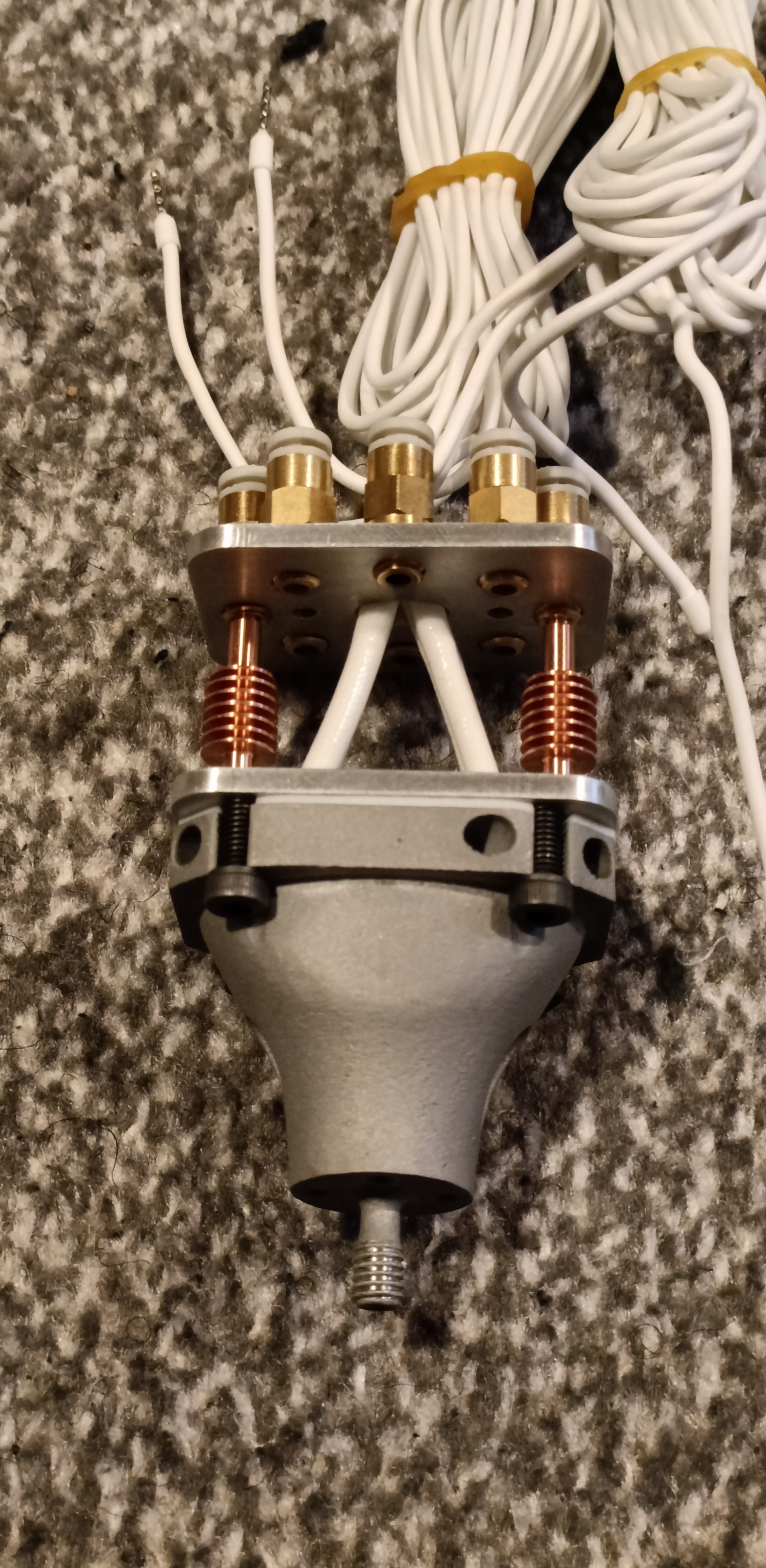
You can also see the kitchen roll I used to prop the X gantry up while I was installing the extruders. I then put black filament through (so that I could easily see it through the PTFE) and pushed untill I couldn't see it anymore and then pulled back until I could. Then I'd look at how much I pulled out and if it was about the length between the heatblock and the coupler, I assumed that it went all the way in. For those that didn't, I unplugged the PTFE tube, thread some filament in (approx 40mm) and then thread that into the coupler before putting the PTFE back on. That seems to ensure that the PTFE is properly aligned as it solved the issue every time so far.
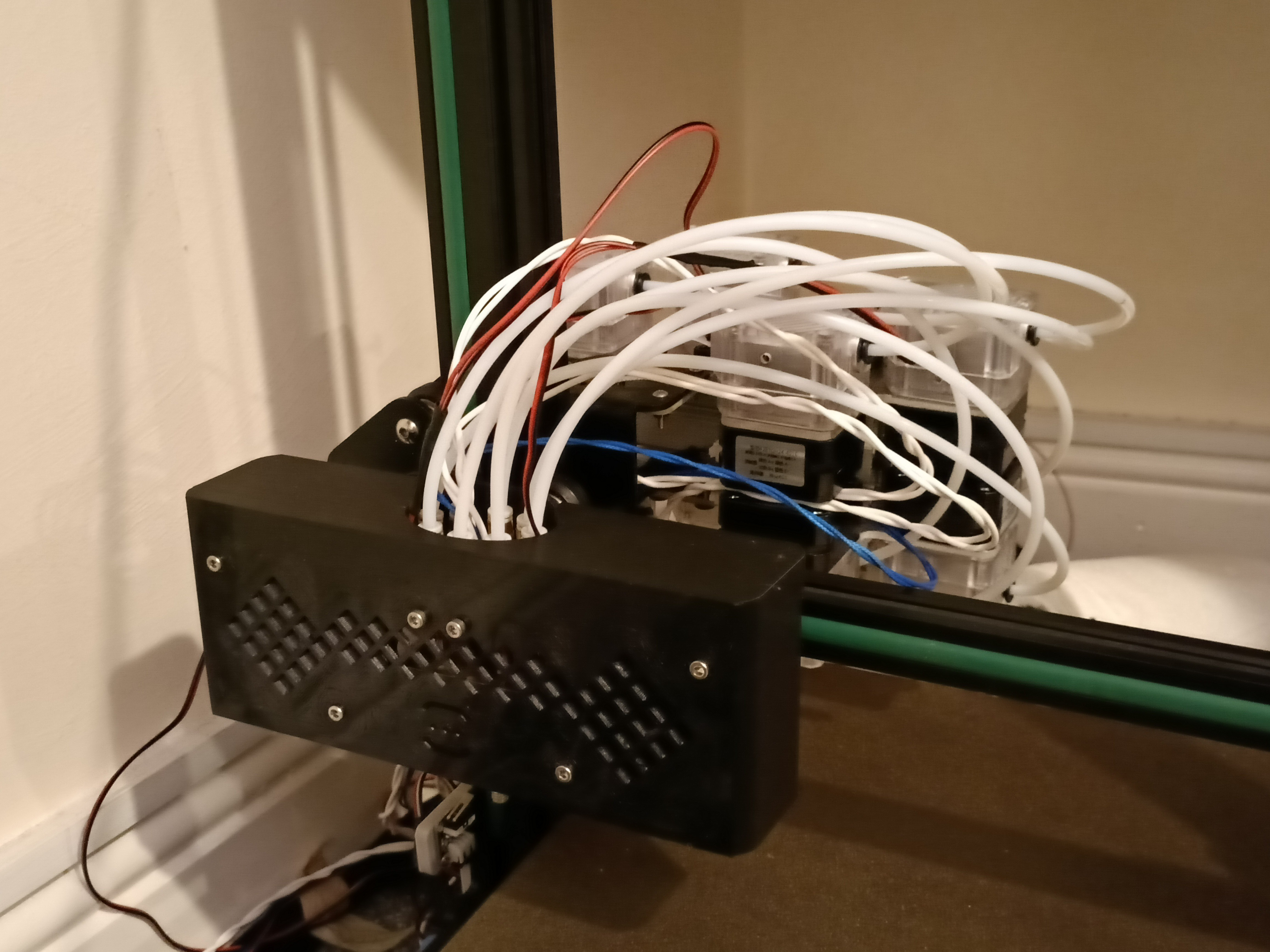
Lastly, I installed the cover:
I wasn't expecting the end result to look so messy.
-
[E2][P][A] Clamp face flattened, motors installed and holder attempted
03/12/2024 at 12:42 • 0 commentsHere's a progress update of what's happened in the past 2 days.
Face flattened and holes tapped
The technician sounded impressed by the aluminium 3D print, but could visibly see that one side of the supposed-to-be-8mm section was shorter than the other side. When in the machine, I believe he said that there was 3/4 of a millimetre in difference between the left and right sides. We assumed that the bottom face of the 8mm thick section was flatter. The M6, 3x M4 and 4x M2 were all tapped. I also got some M4x6 grubs and M4x12 and M5x12 bolts for the coaxial heatblock and motor mounts. I chose M5x12 for the latter as they only had 5x M4x6 in stock and much more M5s, and I conveniently designed the motor hardware to accept M5s.
The clamp bolts stopped turning essentially immediately when tightening. I tighten each pair of diagonals. The gasket was also a lot easier to align now. Did a test fit and it all goes together rather nicely. Not quite sure how much to tighten the heatsinks though. I also looked at the gasket again and there were light arc indentations, suggesting that the PTFE is still flexible enough to provide sealing.
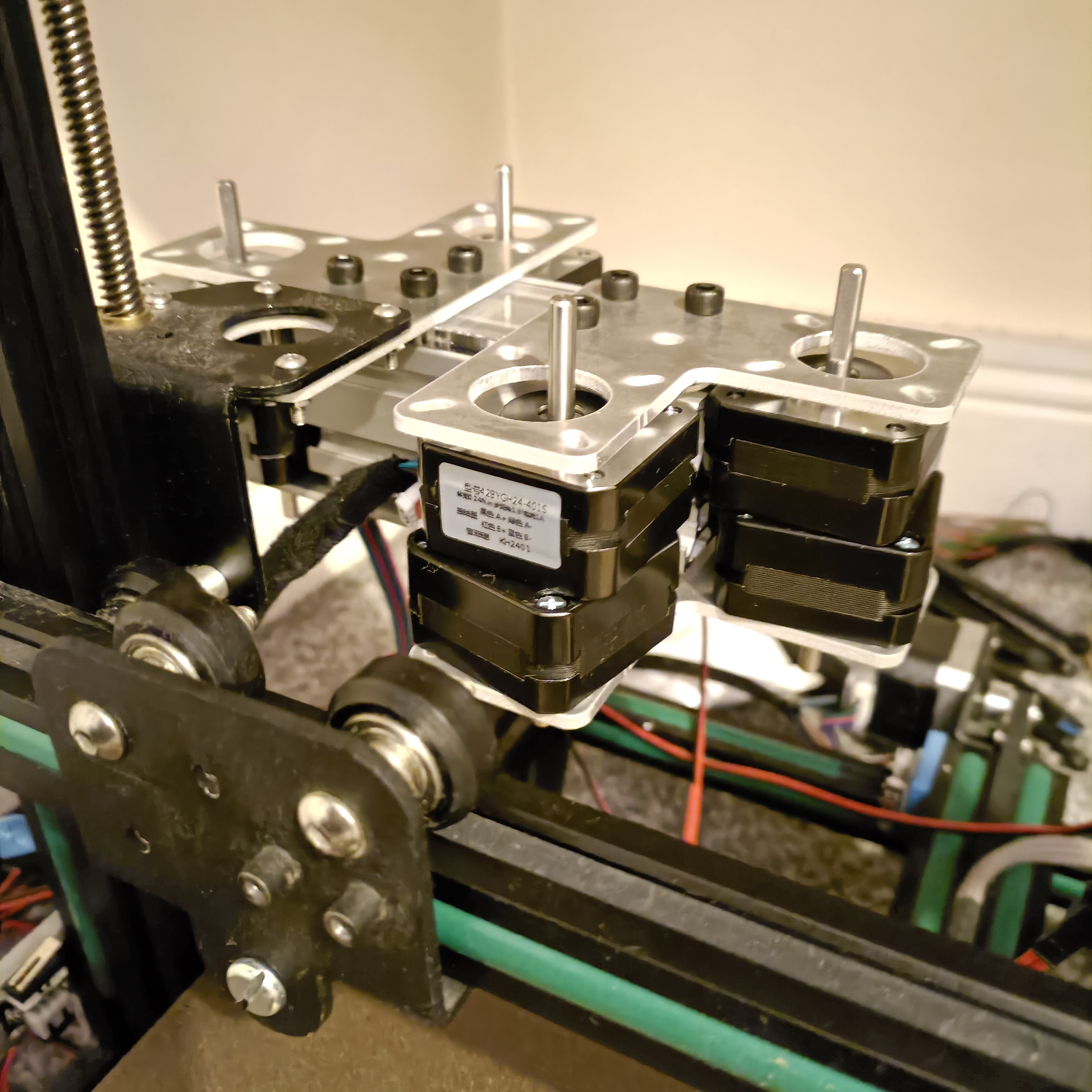
Motors installed
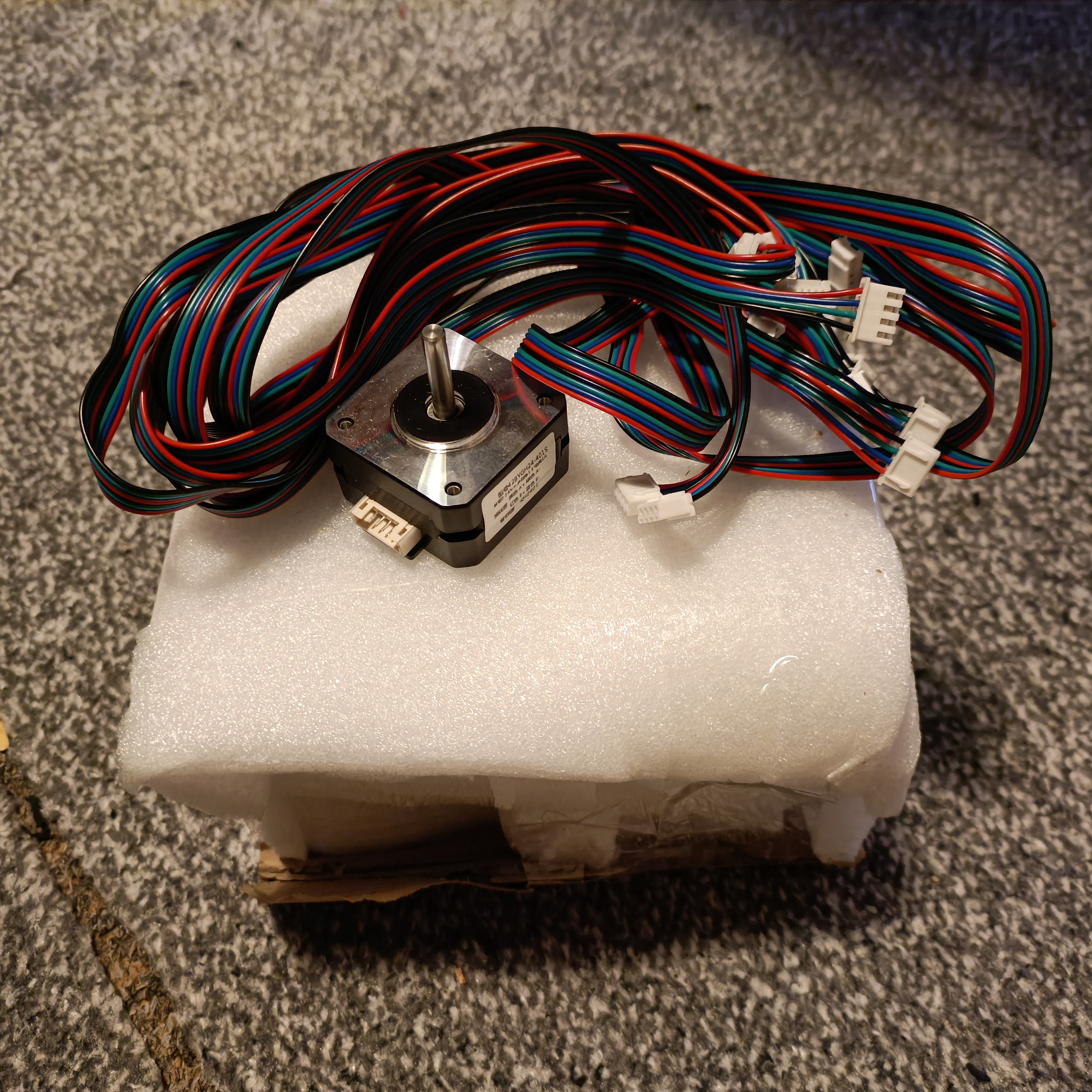
As it turns out, the cables that came with the motors are actually doubled up. It's an 8-wire ribbon cable that terminates to 2 motors on either end. I was trying to get some convoluted method so that i could identify which cable is what, but then I remembered that I bought some numbered cable markers and just used 2, 4, 6 and 8 on the motor that has the left termination on the Oct Pro (so Extruder 8 would be the last extruder). It does seem that the 1m cables will reach the expected location of the Octopus Pro
Then I tried Tesa fabric tape for the first time and it does look a lot better and more professional than multicoloured ribbon wire.
Also notice that I was able to find a thin-cap M5x25 bolt and I was able to use a regular M5 nut on the X carriage.
Right now I'm just waiting on bolts and wires to come in so that I can put the DDEs on.
Hotend holder and cover printed
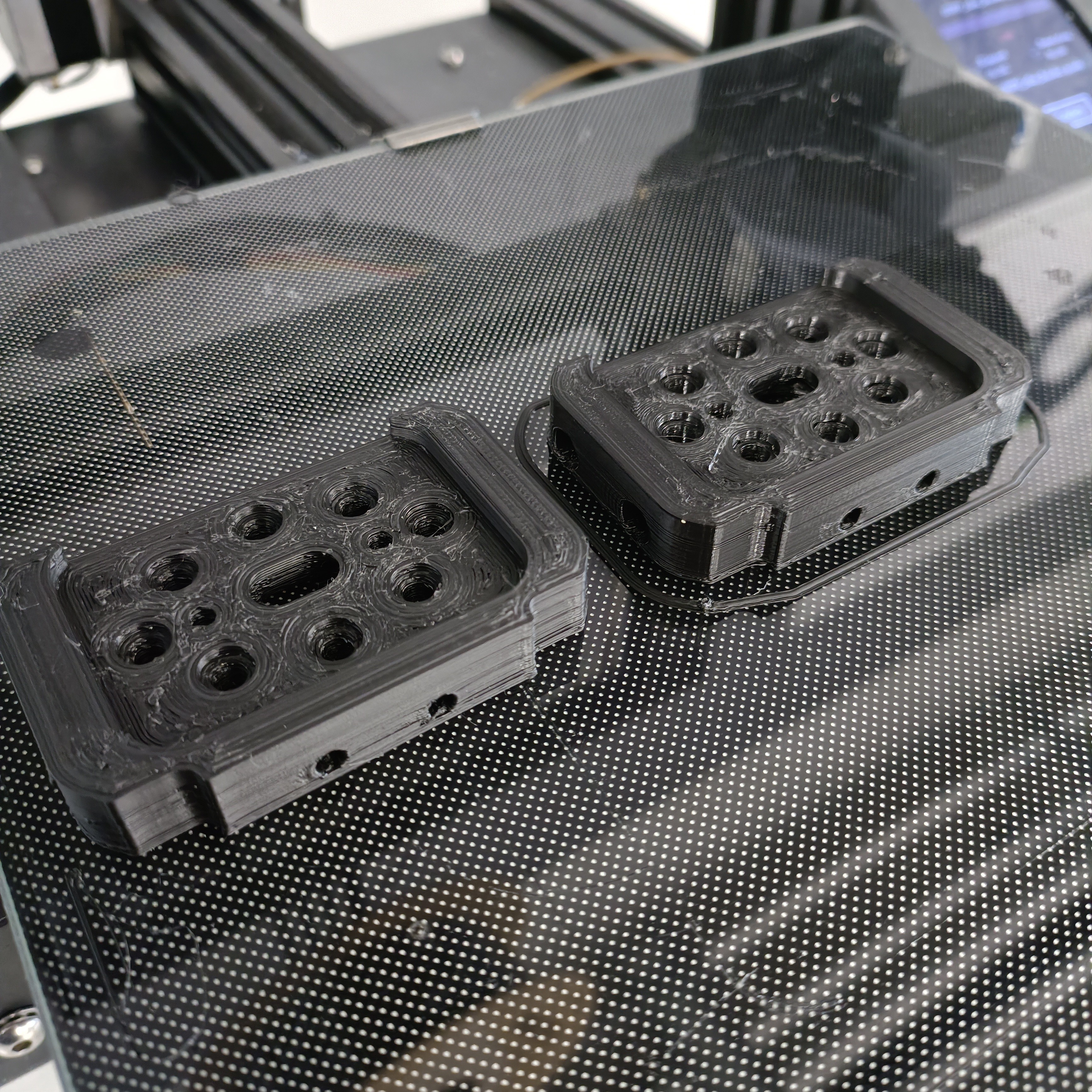
It's been a while since I've used the 3D printers my uni happens to have. First time using this bed material and it looks and sticks well so far. I had to tweak and redesign the hotend holder twice due to tolerance issues (and I didn't have M3x8 bolts like I thought I had, but loads of M4x8s). [13 Mar: 05:00] I've put the hotend mostly together, but understandable misalignments mean that I'm not quite able to align and fit the 8 PTFE couplers:
[13 Mar: 17:00] Lots more printer tuning and for an extra 7 mins of print time, the print came out much better:
New print on the right. The improvements are mostly dimensional accuracy, but the walls also are visibly better. It still didn't work though, but I was able to get the heatsinks to align when the holder was not installed, allowing filament to slide through a bowden tube without it catching hard on any surfaces. Thus, it does seem like it's still a hotend holder issue.
-
[P] Coaxial8or aluminium 3D print
03/09/2024 at 05:34 • 0 commentsSince this is March -- when most of my university-related StepChanges (deadlines wherby there will be a change in conditions/considerations afterwards) are -- my time utilisaton would probably be seen as >97% if there was a Task Manager for it.
Some nice news is that most of the coaxial8or-specific things have arrived, including the coaxial8or heatblock itself.
Coaxial8or
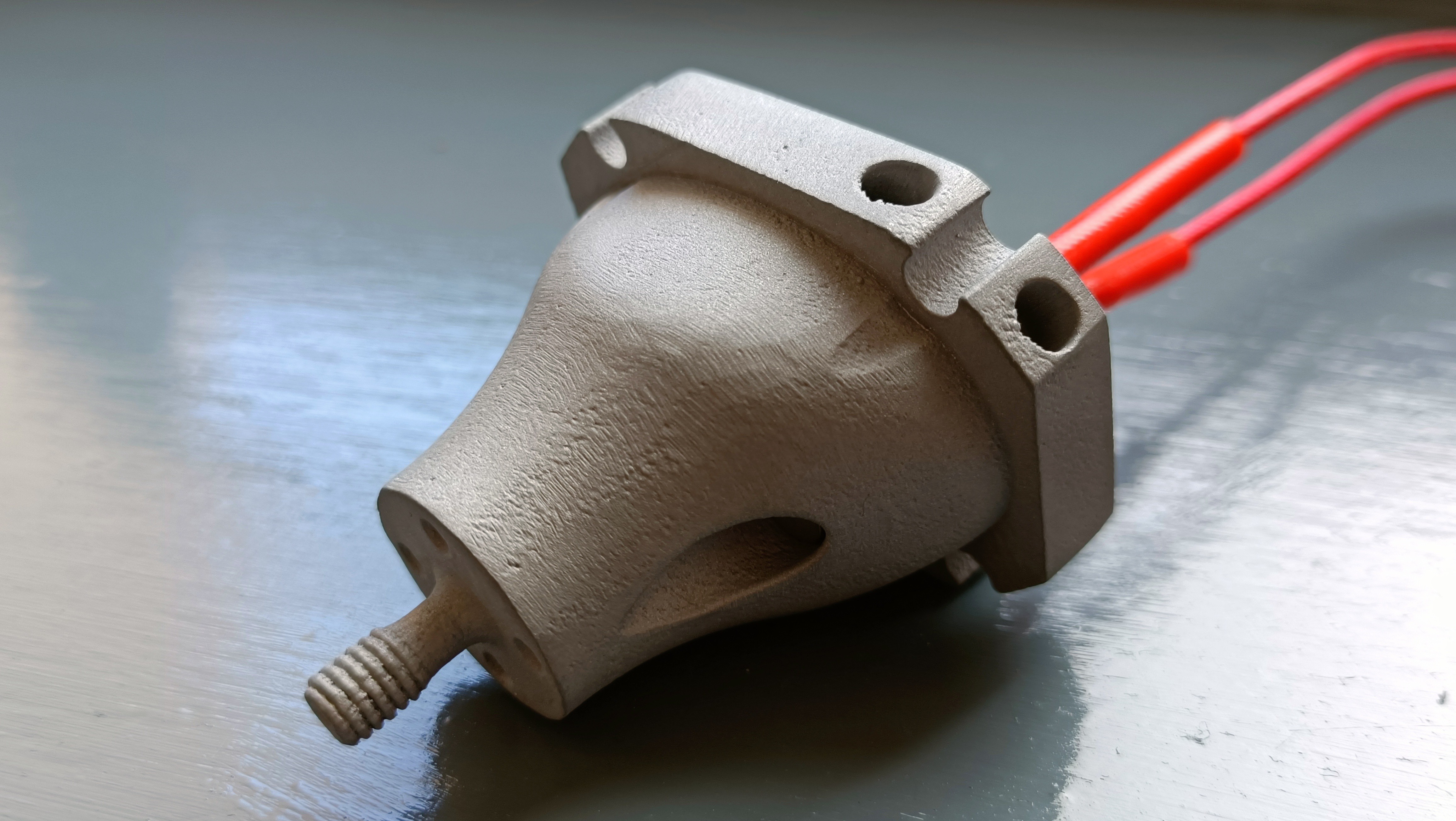
Images of parts 3D printed from PCBWay's aluminium service are few and far between, so here's mine:
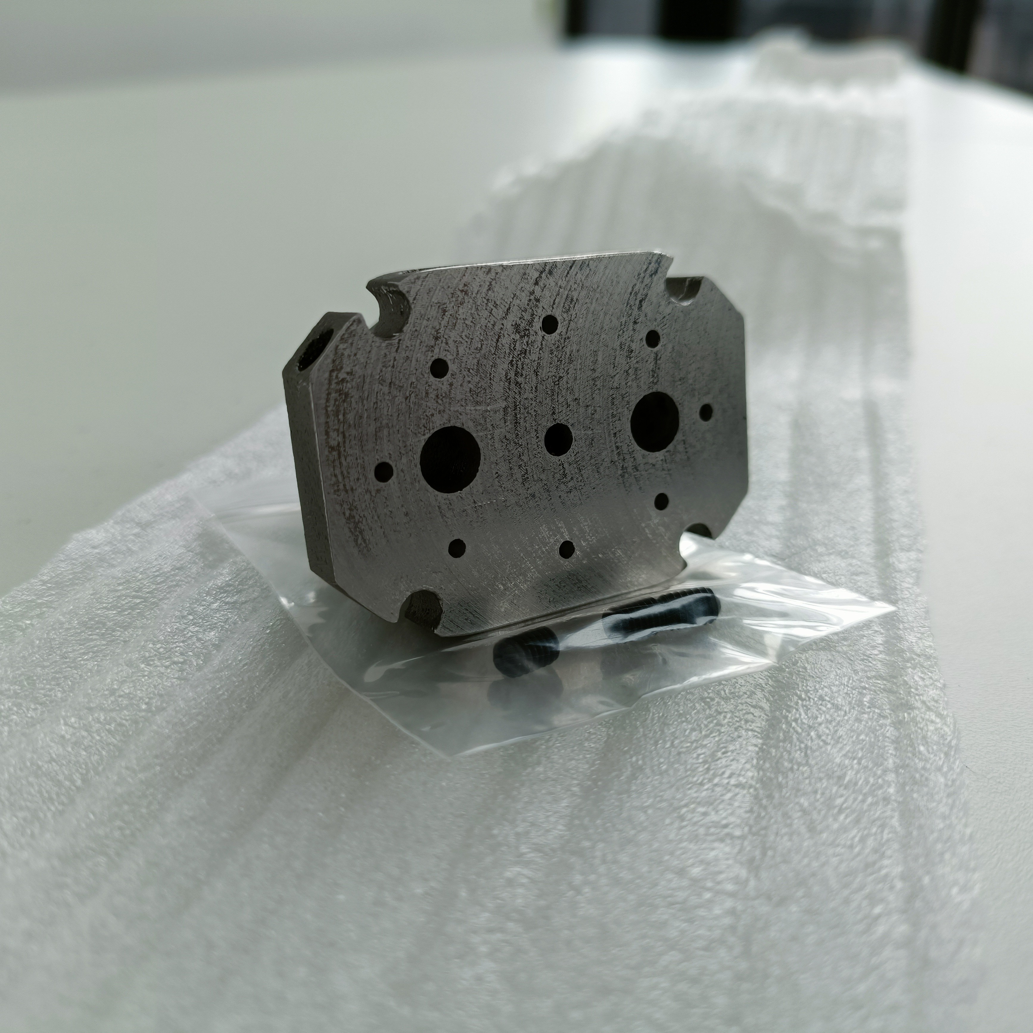
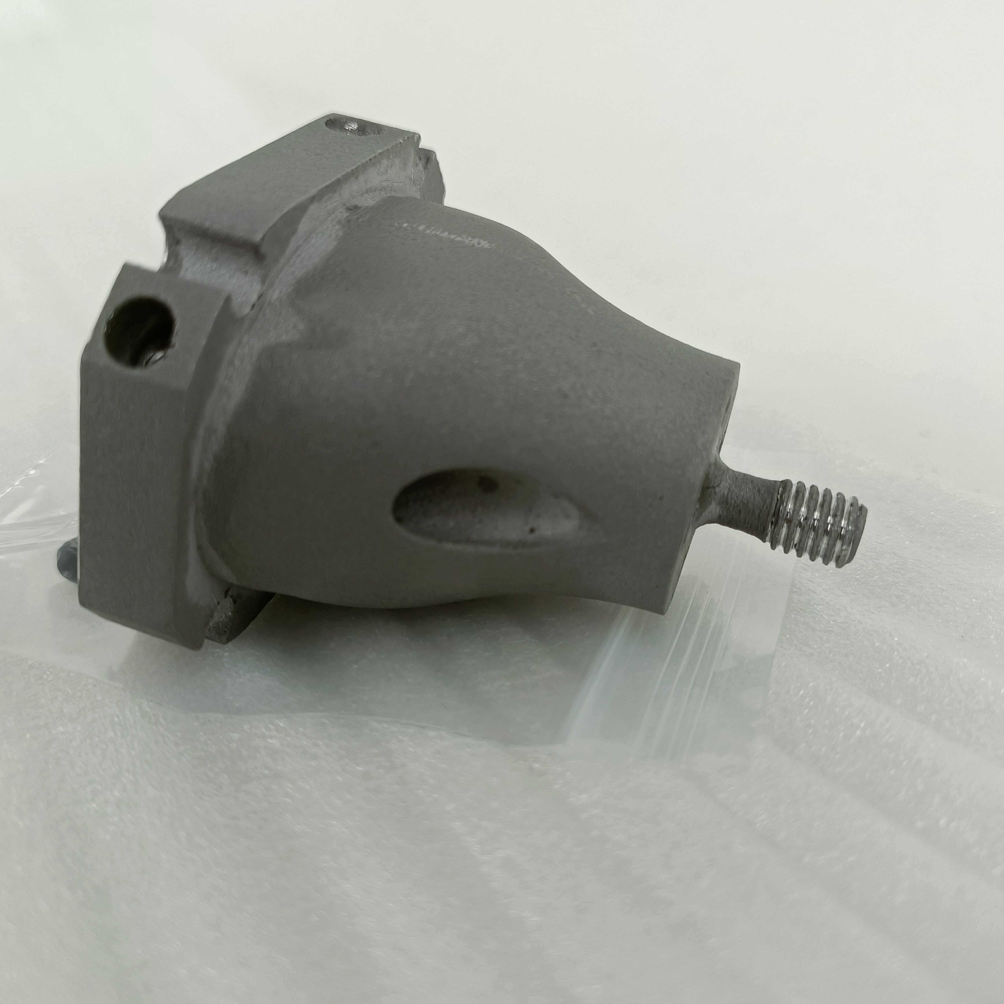
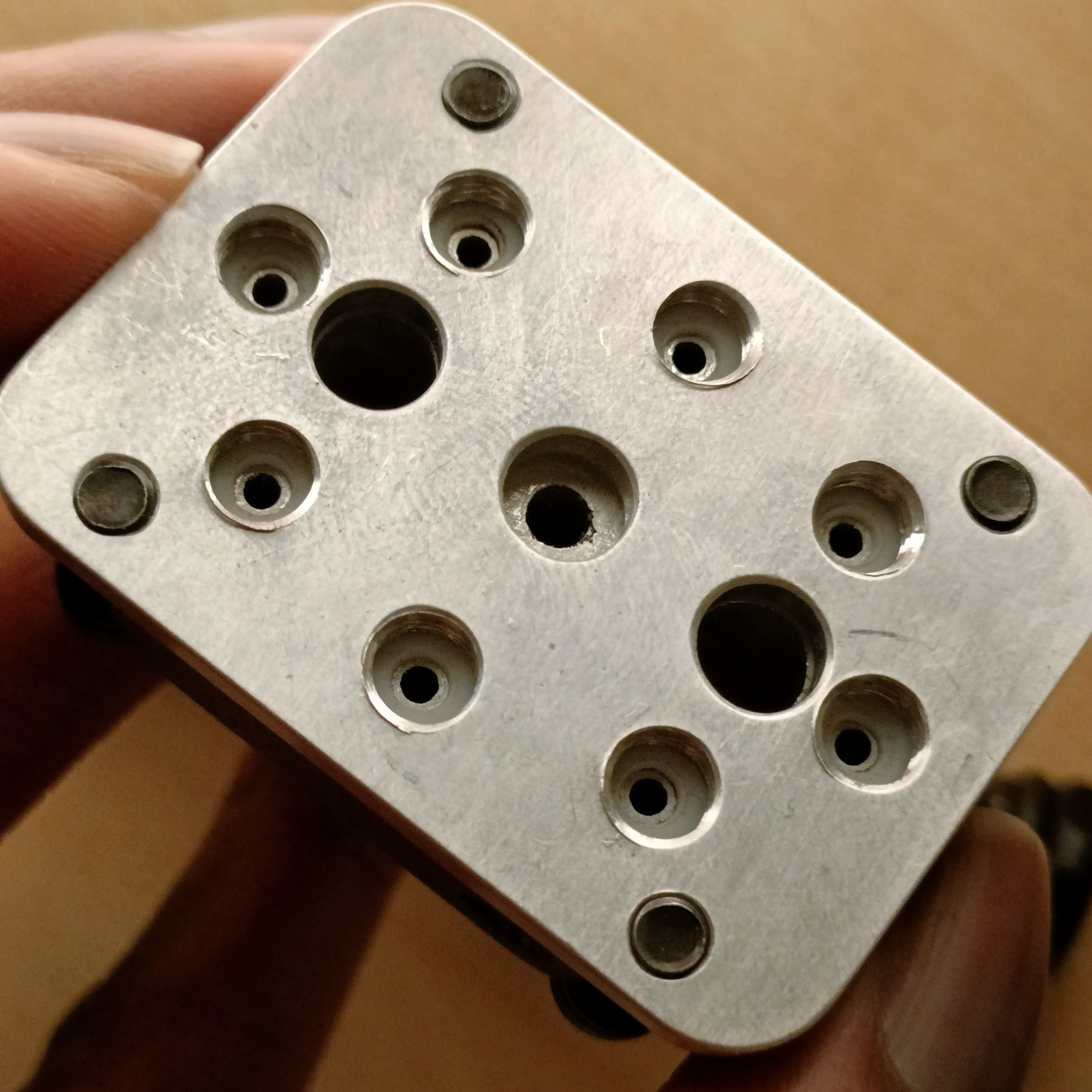
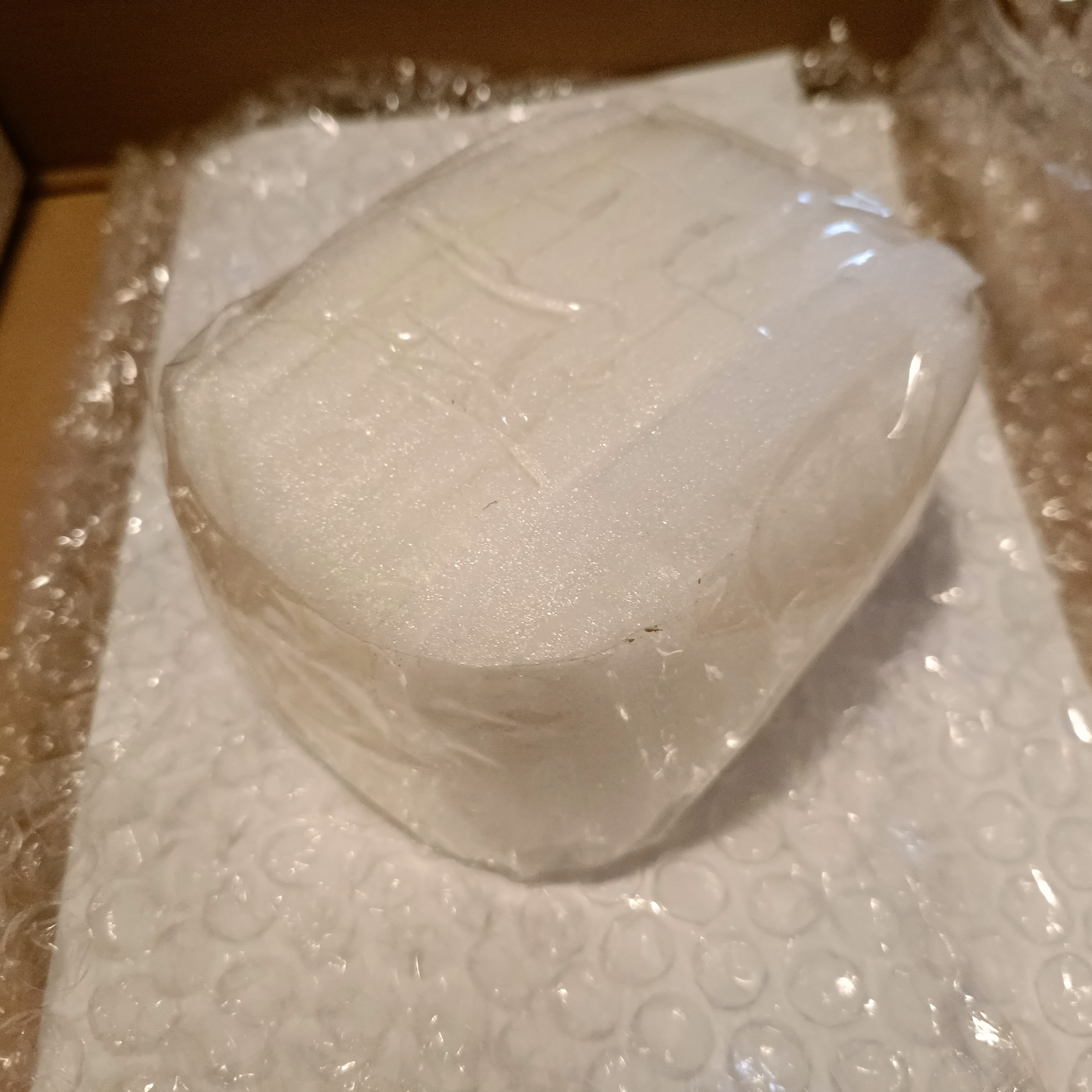
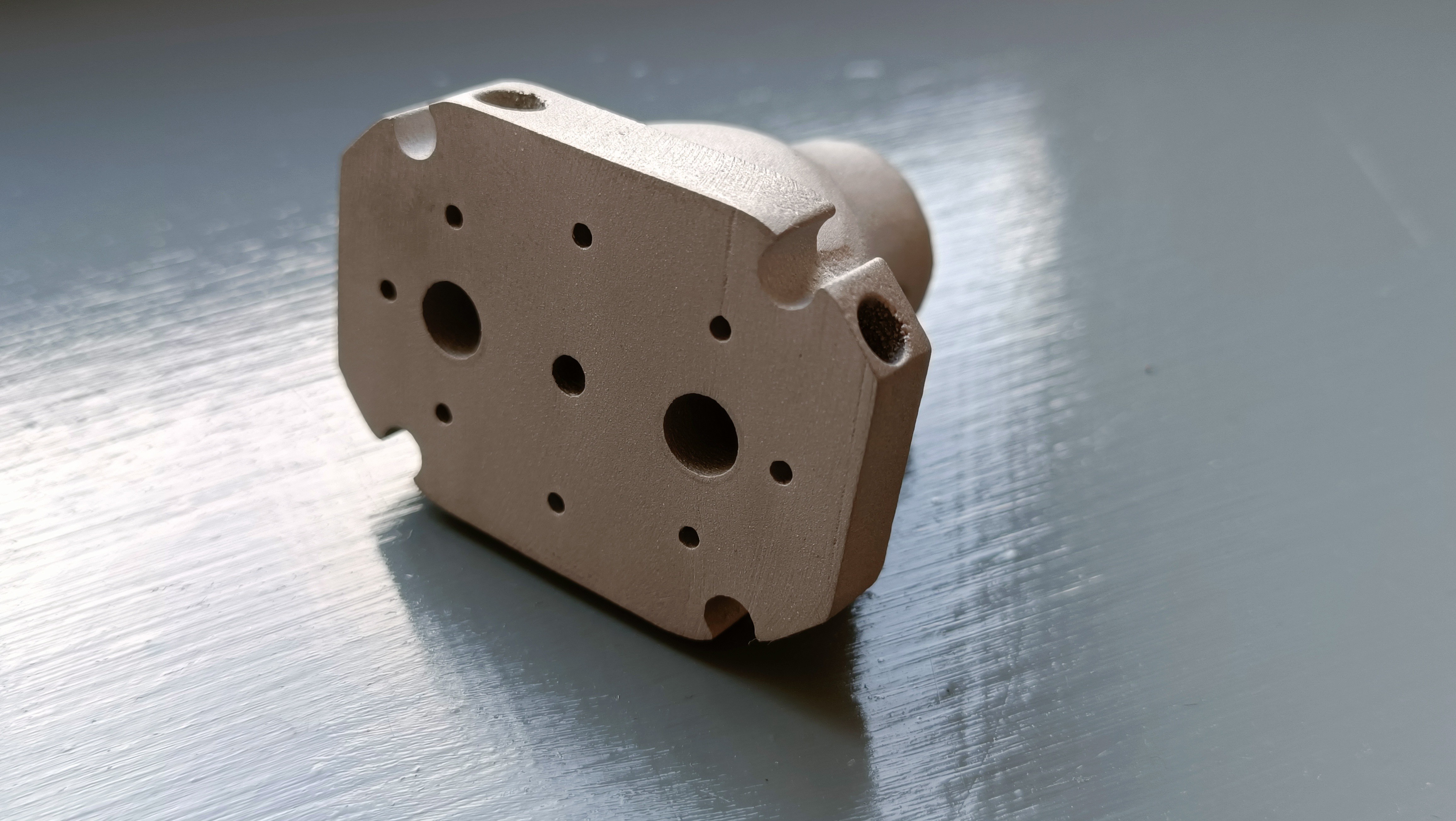
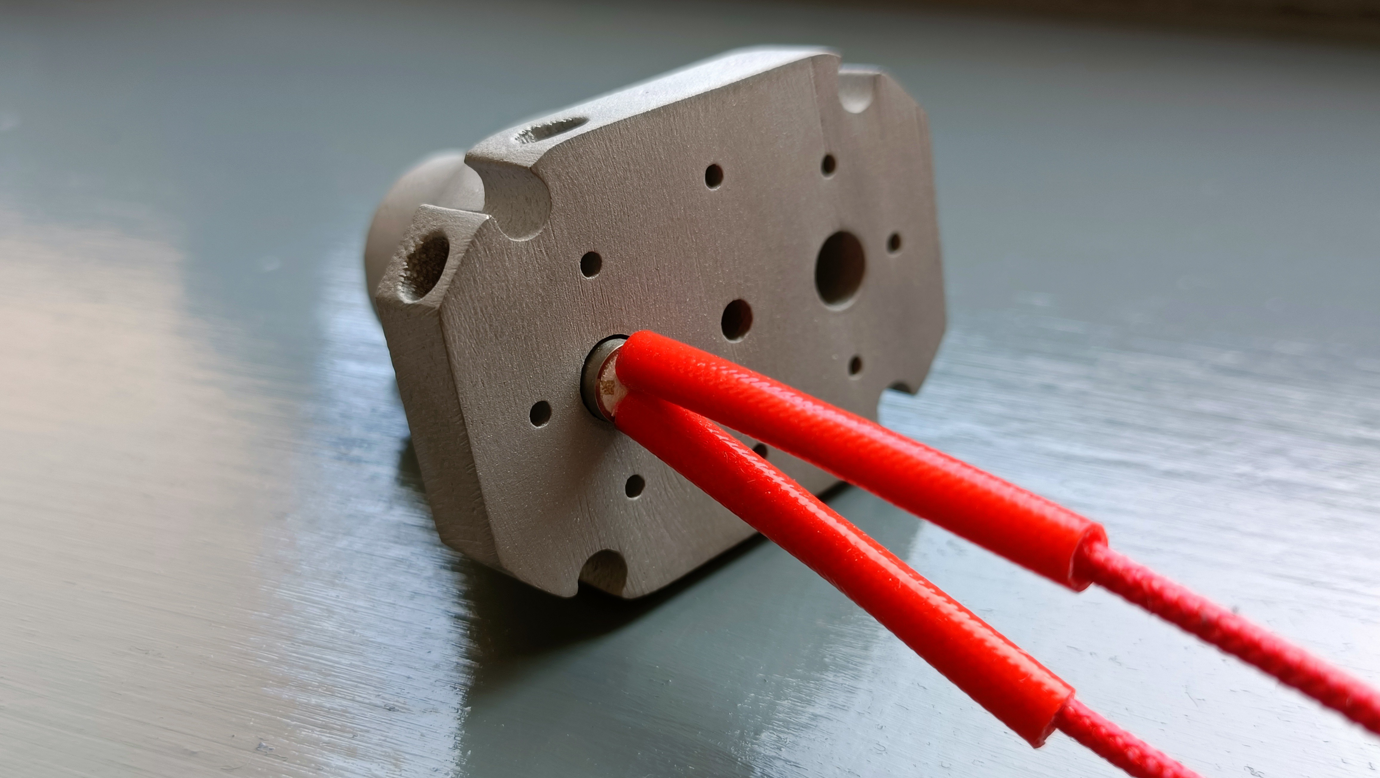
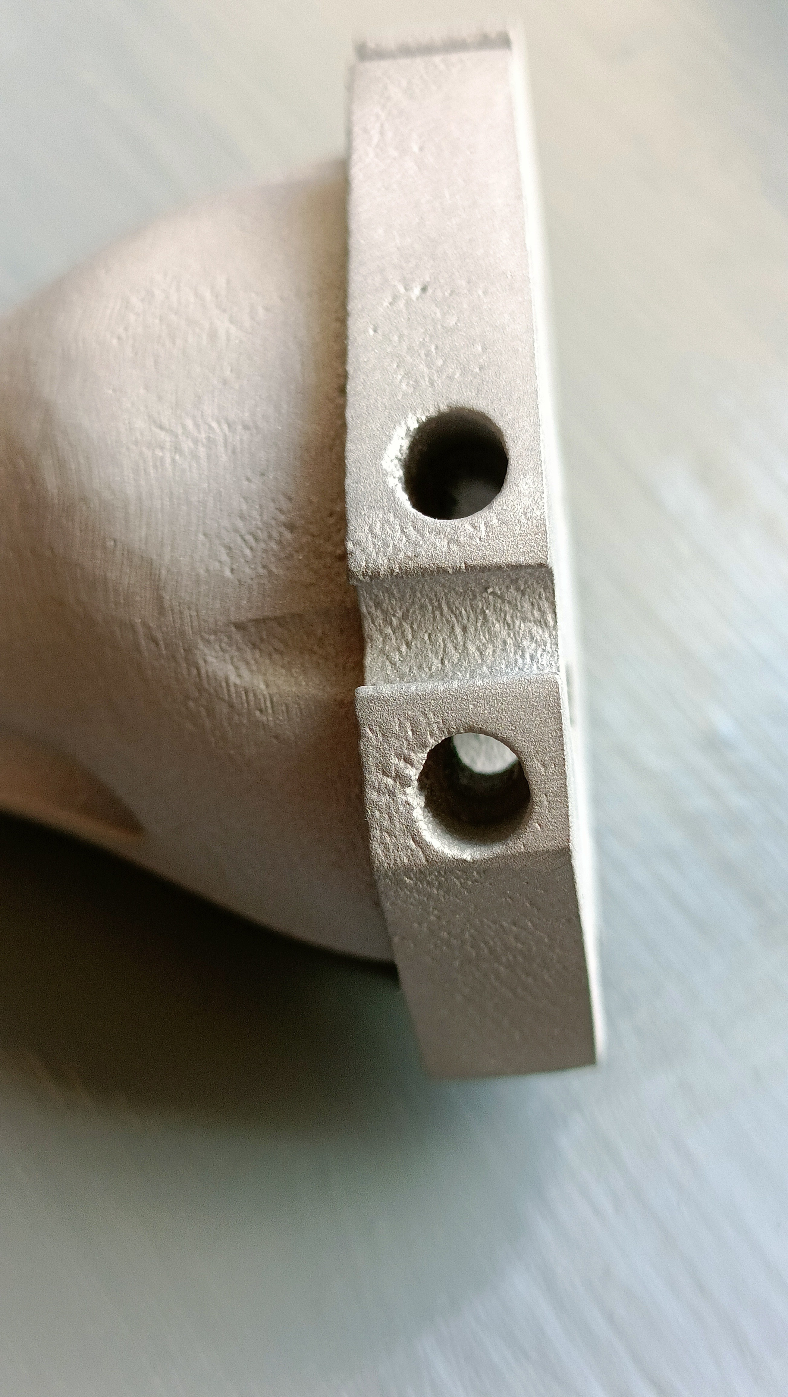
Large box but packaged well. The first thing I noticed was how nice the first-layer surface was. All other surfaces look like a relatively smooth and slightly porrous-looking cast part. The first layer isn't perfectly flat, but hopefully the 1mm PTFE gasket can accomodate for this. There is a slight amount of wiggle room for the cartridge. The M6 thread is expectedly a bit bumpy. Looks like good circular hole overhang performance. I now need to get these M4 tapped. Measuring holes, it seems that they're undersized from the CAD by up to 0.2mm. For example, my 1.9mm filament holes are 1.68mm, the 3.3mm thermistor hole is 3.13mm and the 6.3mm cartridge heater holes are 6.13mm at smallest. With this information, I'd like to predict that the gap between the thermistor sleeve and the 360 degree input channels is 0.75mm IRL.
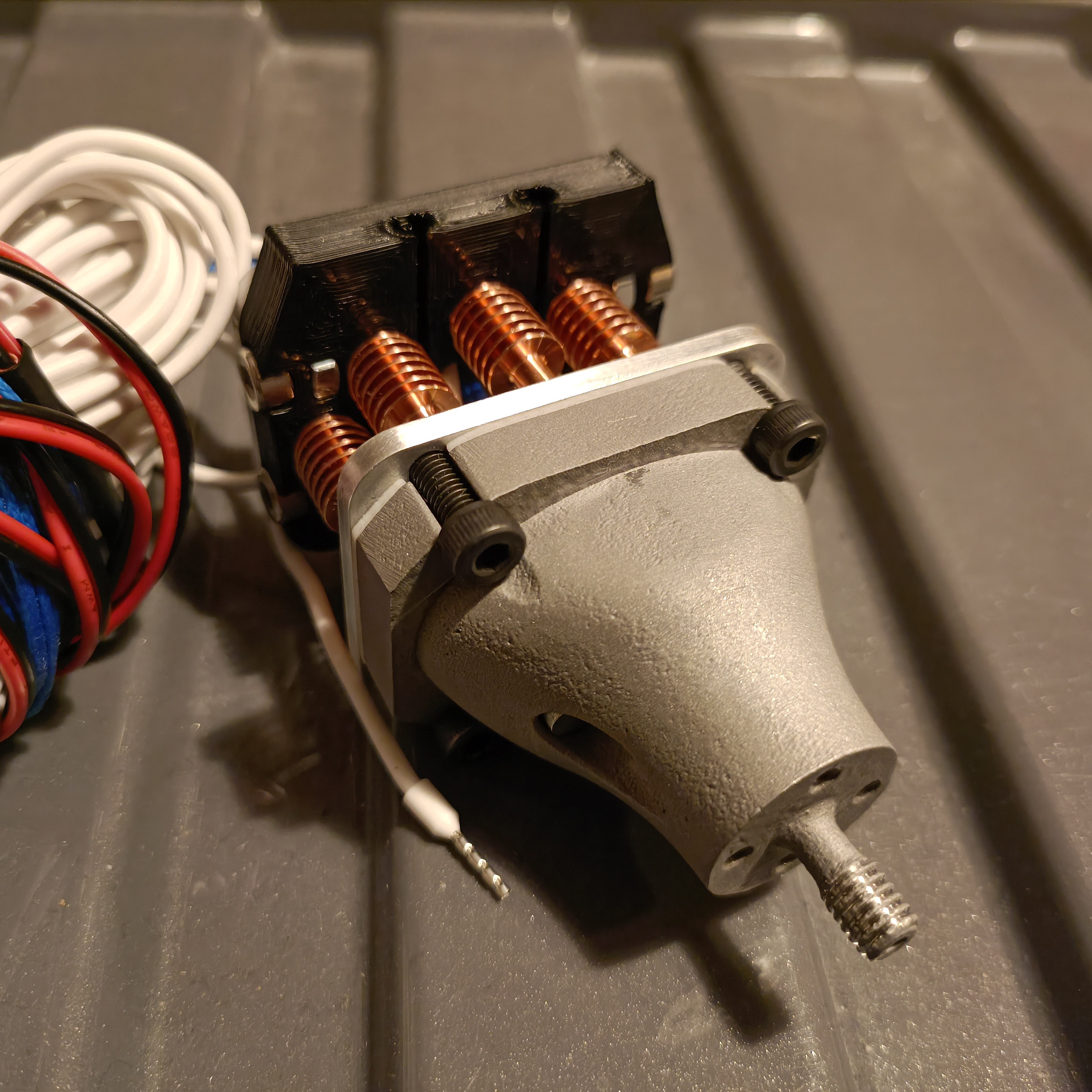
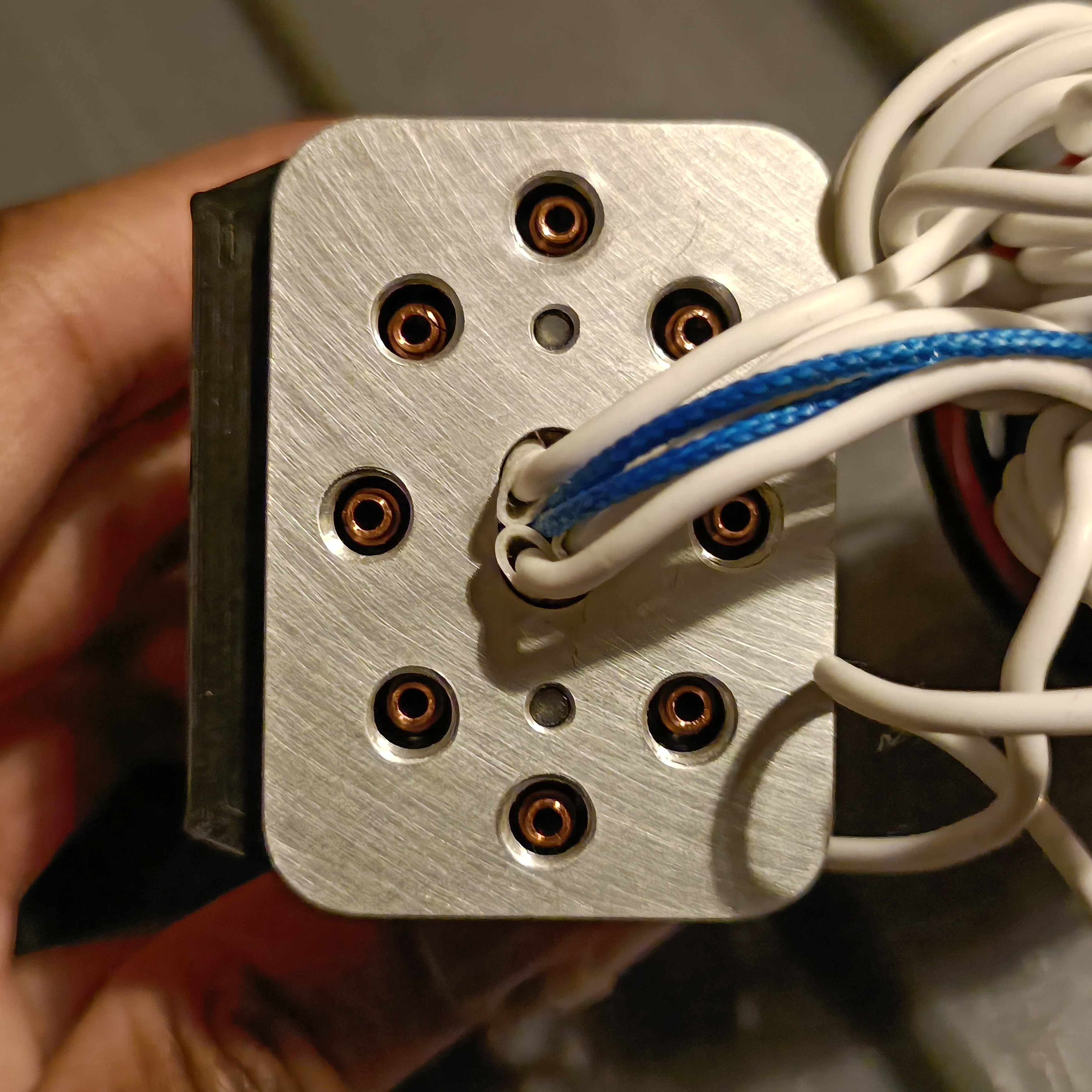
This is the clamp plate, gasket and heatblock all together, and the non-flatness is visible. If the screws are tightened, the 3mm clamp plate understandably bends to conform to the unlevel surface. I'm probably going to play it safe and ask around to see if I can get it lathed / sanded flatter.
Other parts
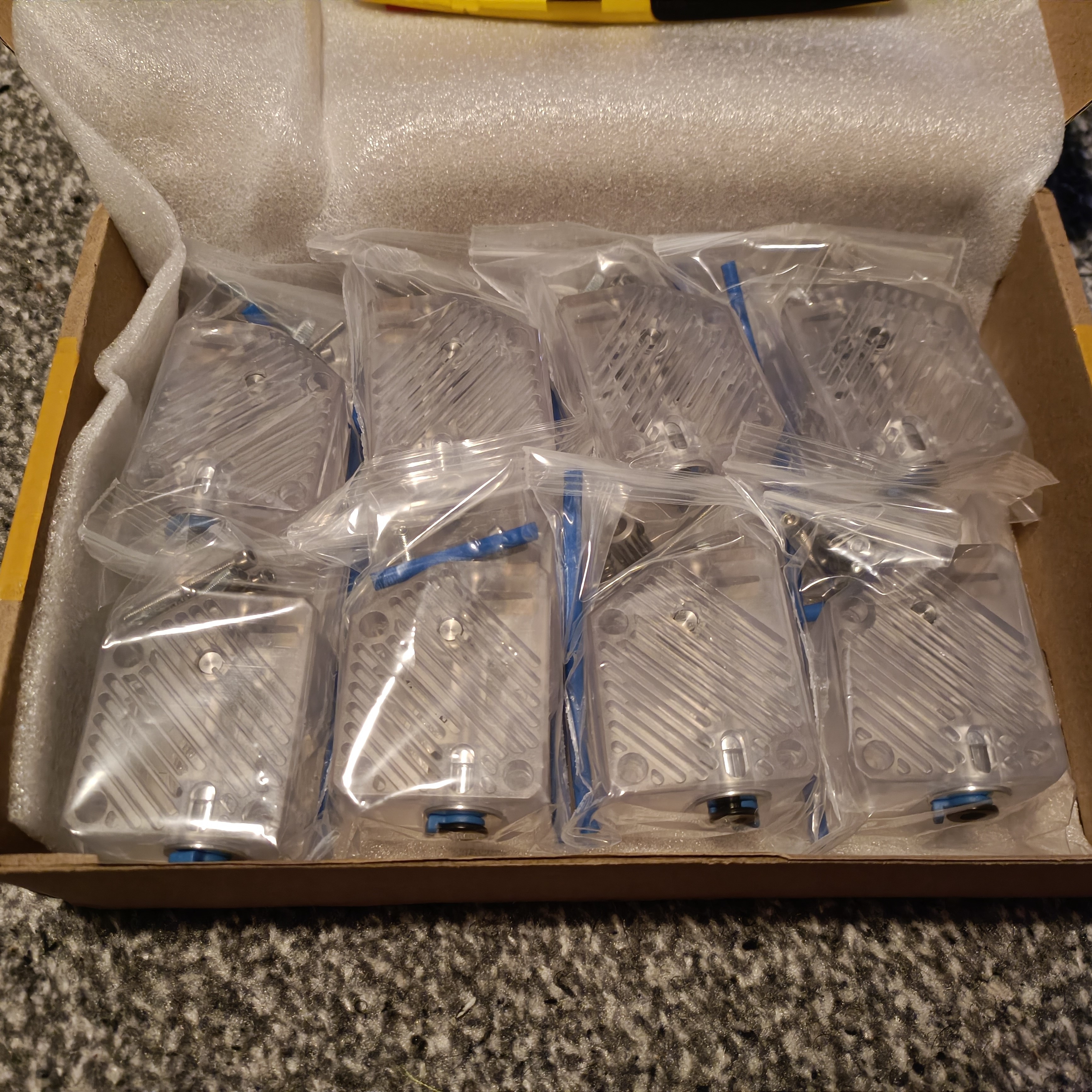
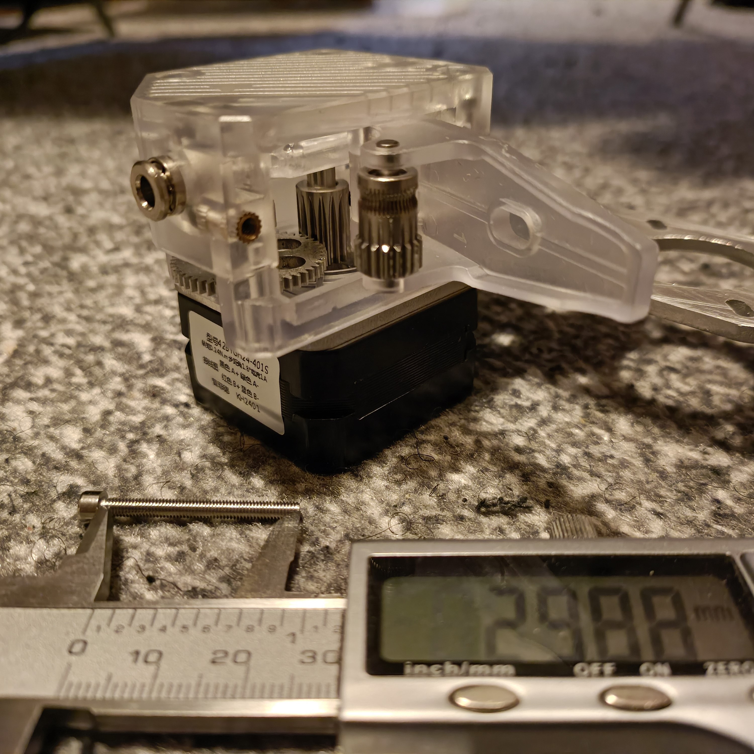
SanBrother DDE x8, with one bag weighing 69.1g, down from the 88g of the current black BMG clones. 0.24Nm Nema 17 motors that I measured to be 22.8mm thick and a weight of 129.6g, compared to the 270g for Extruder1 or 360g for Extruders 2 - 4.. Unfortunately, despite me asking if mounting to a 3mm plate would be fine, the screws that come with the DDE are too short. These screws were flush with the underside of the plate. The max depth of threads on the Nema 17 is 4.95, so it's a close fit with 35mm screws which is the next standard length up.
The thickness of the DDE is 32mm.
As mentioned in one of the reviews, the large metal gear has a small amount of backlash, unlike my clone BMGs that use white plastic gears.
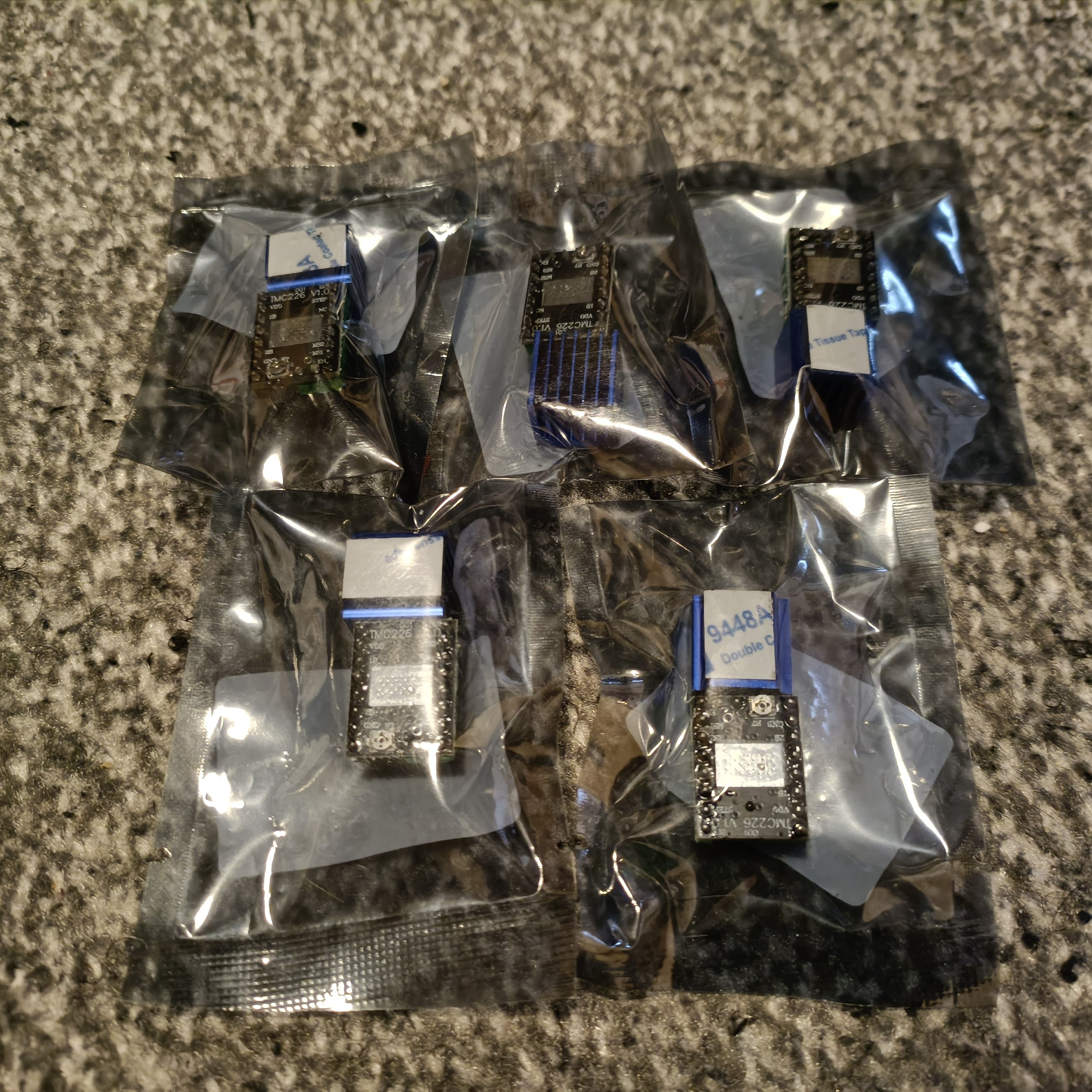
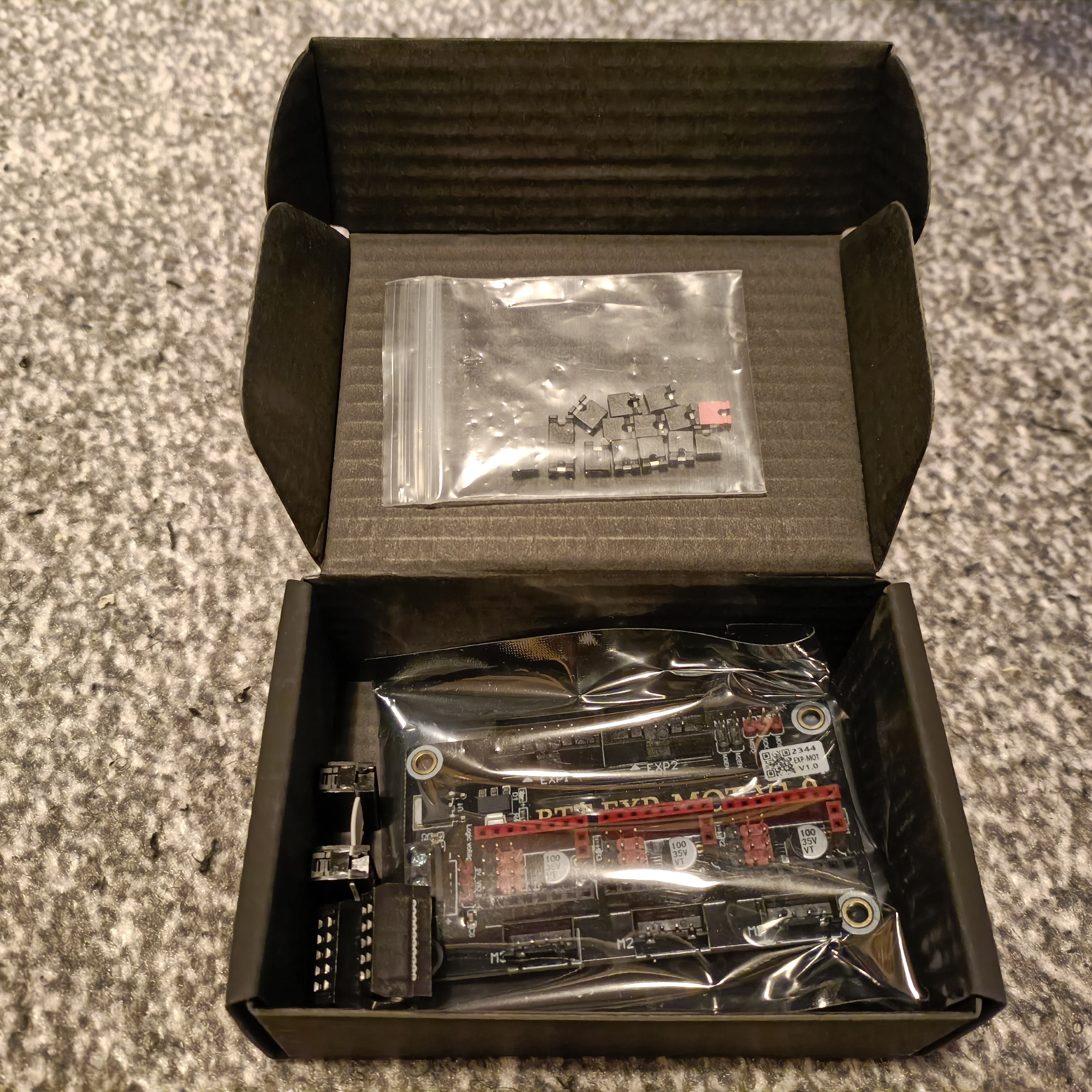
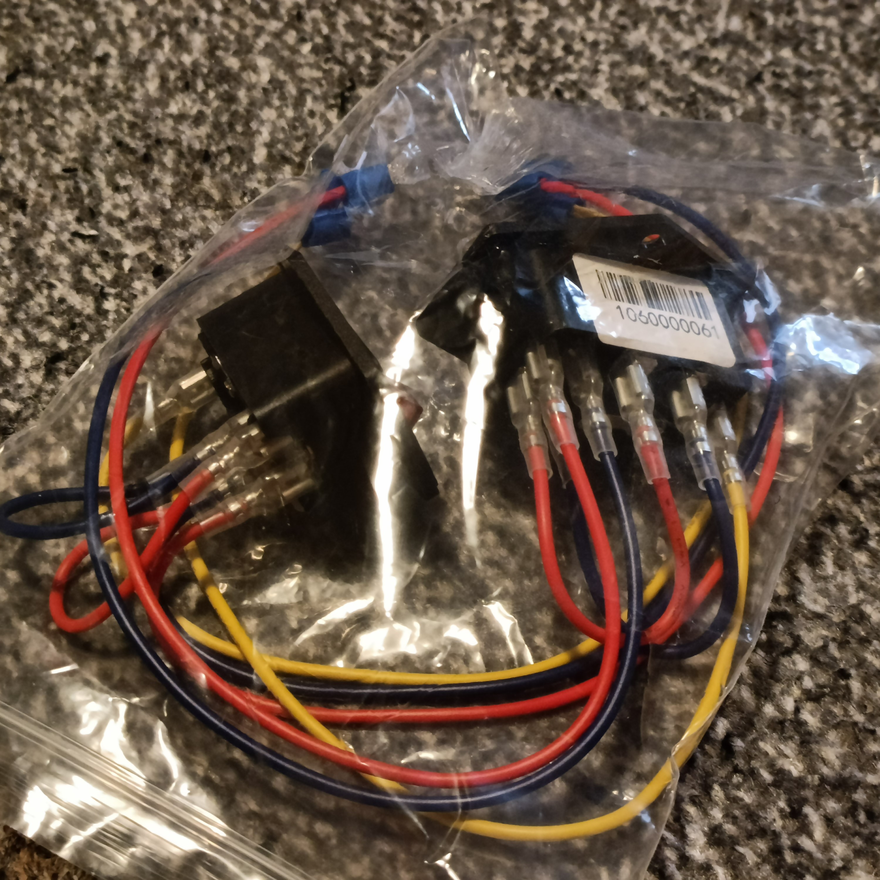
TMC2226s. 3 for XYZ and 2 more because I only have 6 TMC2209s for the extruders. The BTT EXP MOT where the XYZ drivers are to be installed, both taking advantage of the dedicated DIAG pins and meaning all the extruder drivers are together on the BTT Octopus Pro. The heatsinks came and there were notable measurement differences to the CAD, with the most concerning change being that the top cylinder was 2.84mm instead of the estimated 2.65mm. Almost coincidentally, the PTFE coupler hole was 2.9mm instead of the 2.8mm in the drawing, so the two parts can still slot together. While probably not as recyclable as the plain cardboard box I was expecting from the 400W and 200W slim PSU's I bought back in probably 2019, it does look rather premium for the cheapest PSU I've ever bought. This new 400W is actually a centimetre or two shorter than the 200W! These new sockets are notably better than the old one installed in the CR600s as all 3 wires have unique colours. It also looks like they are installed with a double pole switch.
(17 Mar 23 - Turns out that the old ones were also individually colour coded, but the Earth line was a somewhat confusing blue (instead of something resembling the Yellow-Green wire in the UK) and was thinner than the other two wires for some reason. -
[M] Using Fusion's renderer to simulate colours
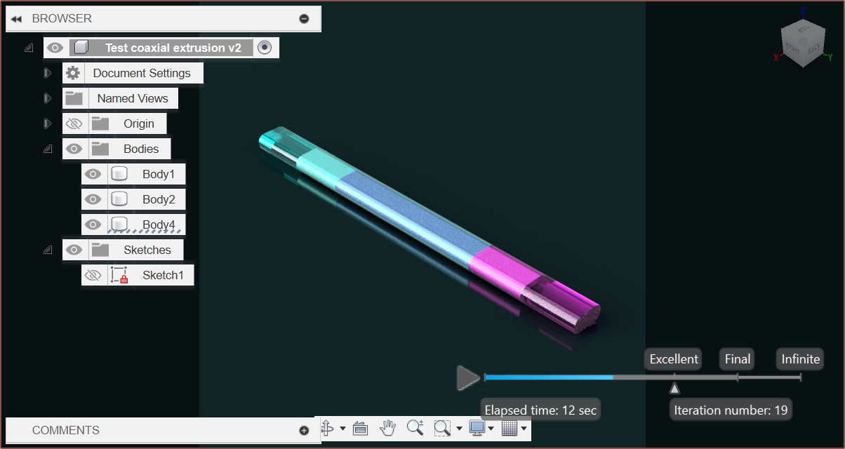
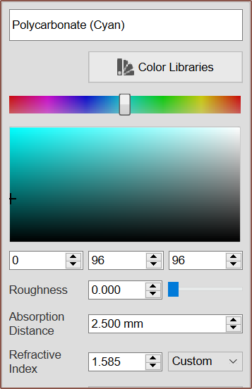
02/28/2024 at 10:01 • 0 commentsTransparent Cyan, Cyan + White, Cyan + Magenta + White, Magenta + White, Transparent Magenta Seems that the most believeable result is to use a Polycarbonate material with the following settings:
In other words, I'd need deep, transparent, CMY filament.
Also note that I had to offset faces between materials by 0.001mm for the render to show up correctly.
-
[P] Flat files fabricated
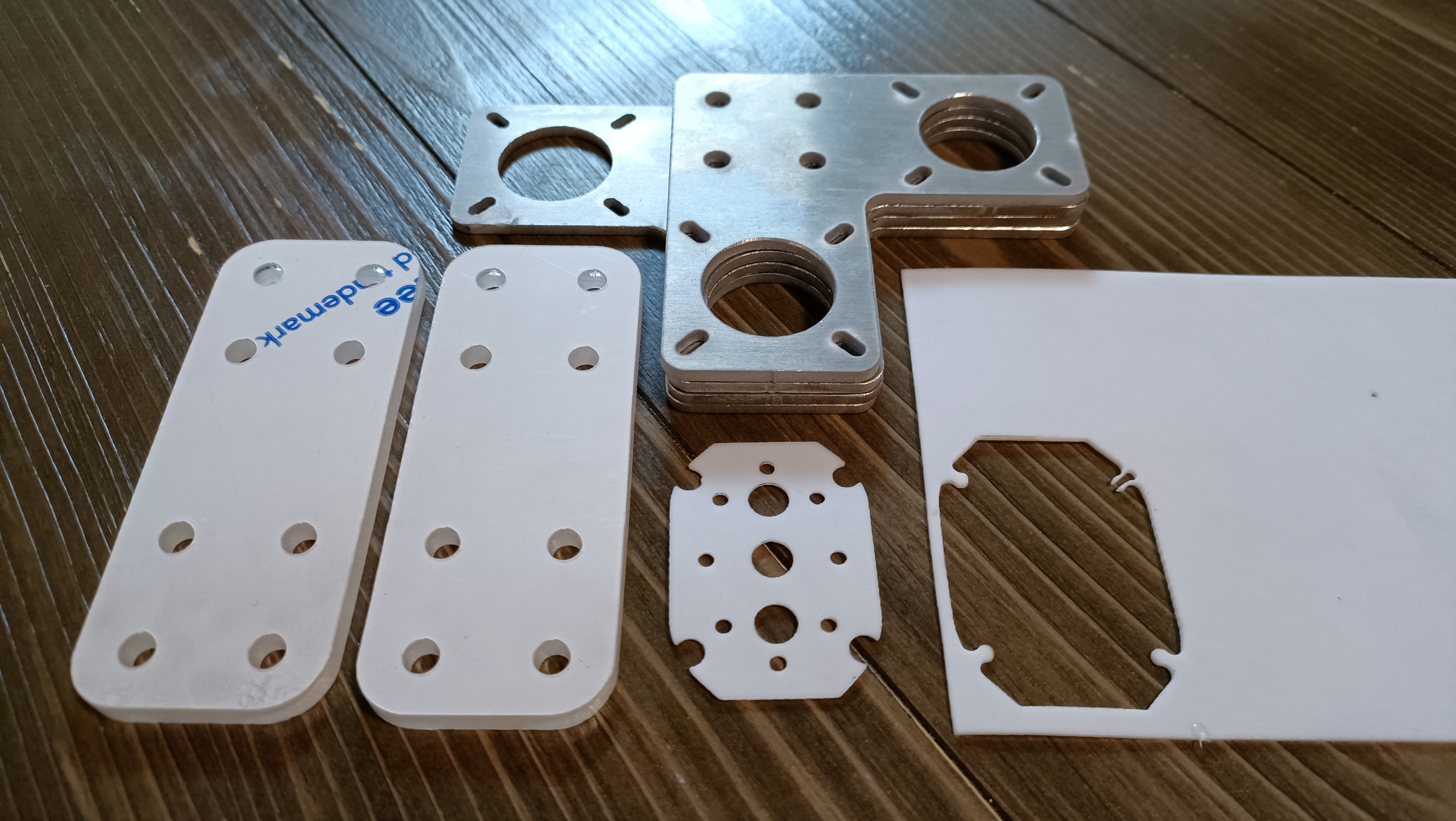
02/26/2024 at 18:35 • 0 commentsThe university happens to have a wide variety of manufacturing facilities.
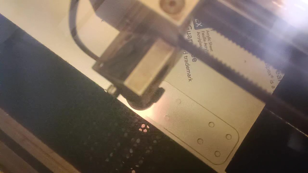
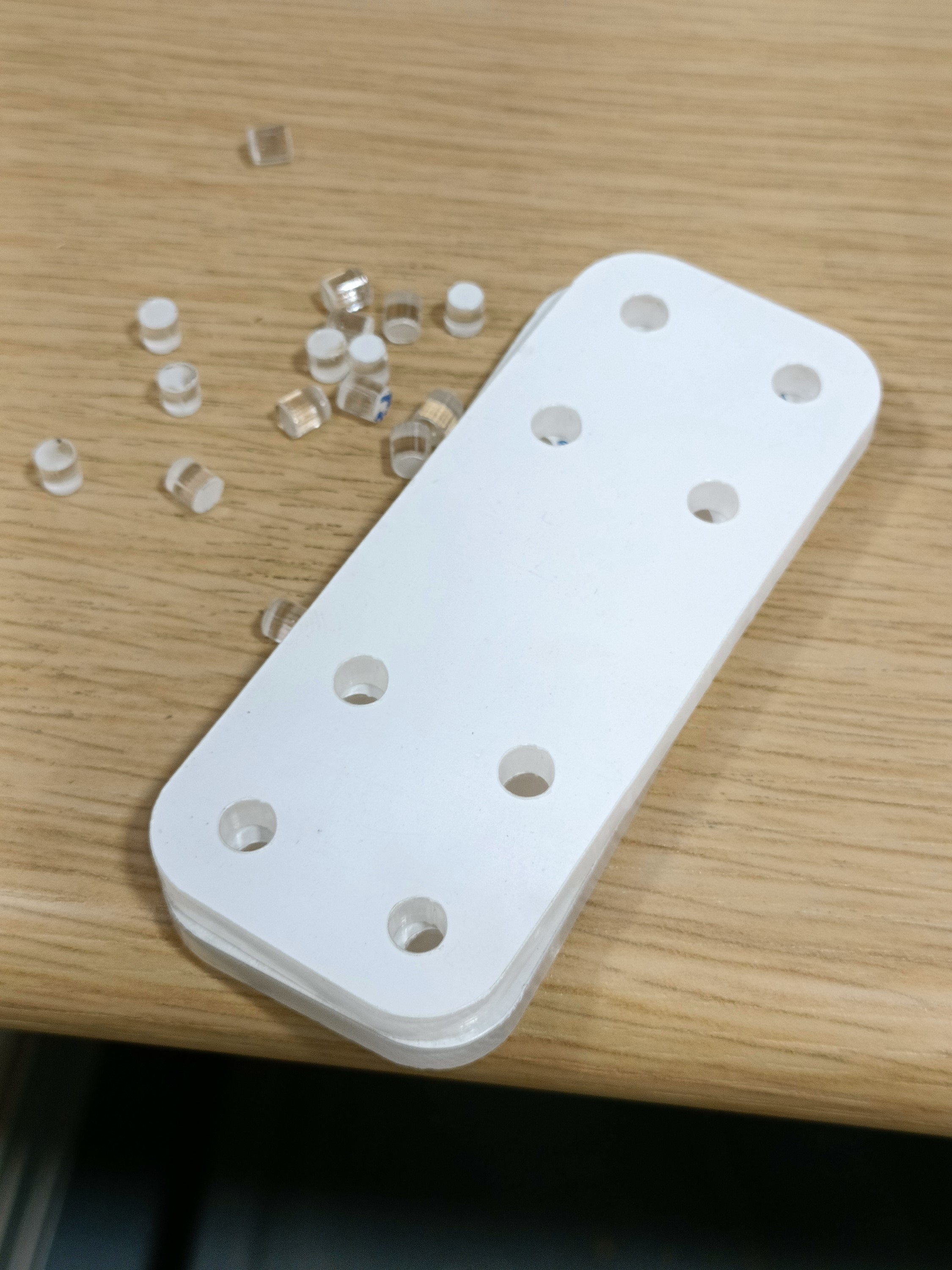
Laser cutting the motor spacers
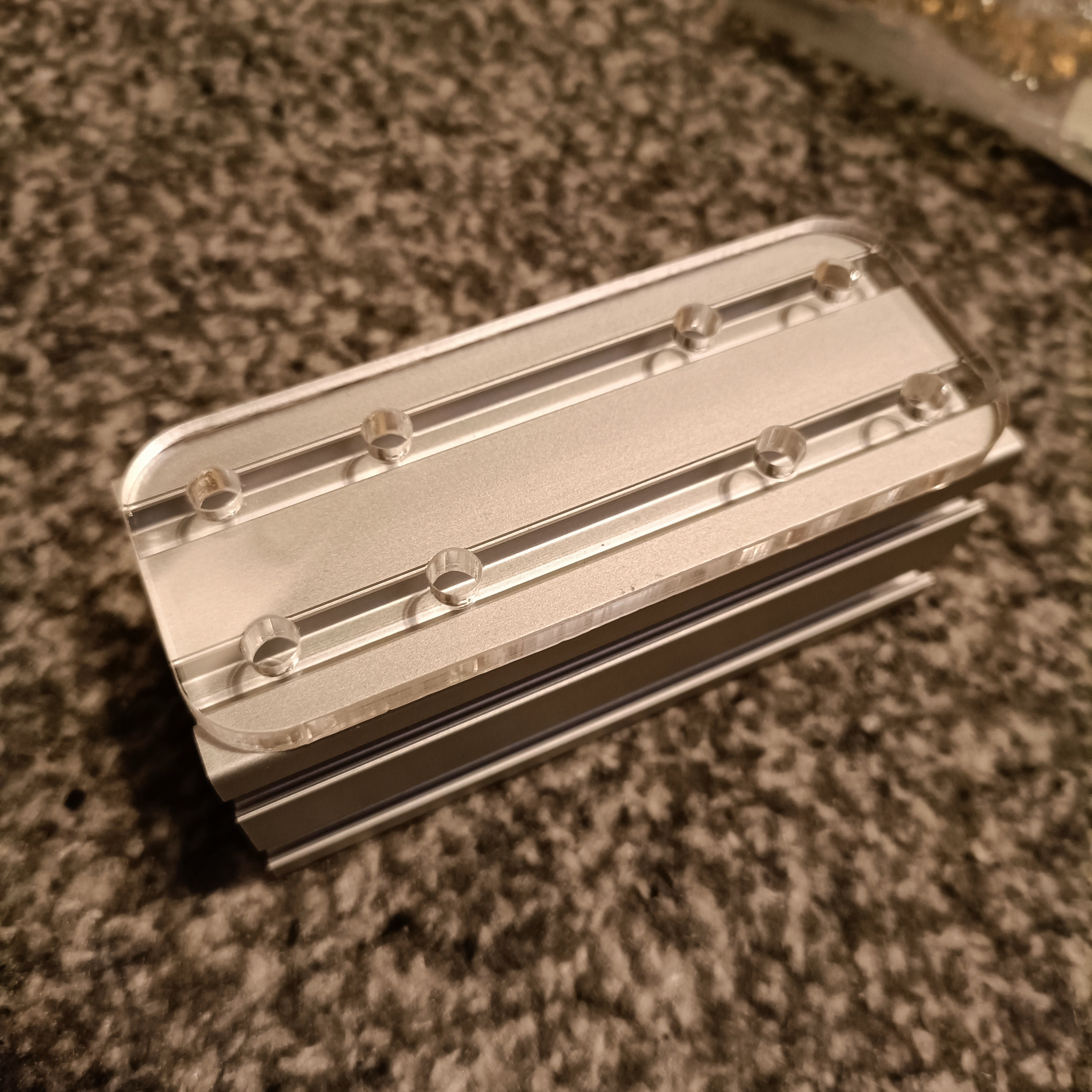
The first thing I tried to do was laser cutting. The plan was to ask for some 6mm acrylic for the motor spacers and then laser cut the 1mm PTFE that came in the mail a few days back for £2 delivered. The original idea was for 5mm acrylic but I thought that I'd err on the side of caution.
The PTFE seller exceeded expectations; on the listing it says "at least 80 x 80mm" and I got a 100 x 150mm piece which is 50% more PTFE than other listings that cost 100% as much. However, the laser cutter technician said that he'd need to ask around to see if PTFE could even be laser cut.
The acrylic was fine though, so we just progressed to focus on that.
We hit a hurdle almost immediately as some software called "ApS Ethos" wasn't showing the .DXF exported from Fusion, even when moving the files to negative co-ordinates. The solution was running it though Solidwords 2023 that the uni happens to have installed on the engineering PCs. ("Awfully recent, if you ask me" I thought, since Solidworks does a yearly edition (that costs money) instead of these sweet 6-week free updates on the Fusion side of life.) It turned a 4KB into a seemingly identical 22KB file, but this showed up in the Ethos software.
Things moved really fast after that. There was only 5mm acrylic on hand so that's what we chose. It's actually transparent so it seems that, unlike the dark-mode theme that my 4-in-1-out extruder setup was, everything is going to be a silver / transparent light-mode theme.
The holes were increased to 5.1mm ahead of time to coincide with the metal plates, and the result were holes between 5.08 and 5.15mm so I think that +0.1mm is fine for clearance if I need another part in the future.
I decided to keep the 4.75mm small cylinders that were left over. I might use them for LEDs in the future. Abrasive cutting the other 2 parts
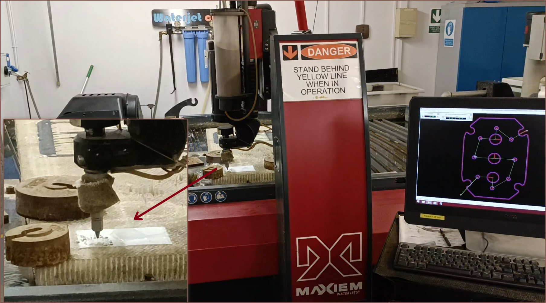
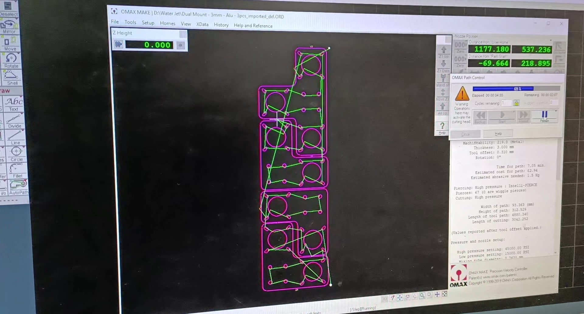
I mainly went to the workshop to ask about the metal plates, as the university happens to have a massive "1530" water cutter, and only at the end did I mention about the gasket I was trying to get cut out. He asked how thick it was and figured that it was cutable.
So, with the soft material cutter my university just happens to have...
Really! Hidden away in an inconspicuous corner, past some flat sheet metal stock (making it seem like an even more inconspicuous corner), was a very large machine about half the size of the water cutter which is made by the same company. It's like a water cutter without as much water, from what I could tell. It's also so much louder.
So I gave the PTFE to the first tech that I spoke to and he said that he's never handled an entire sheet of PTFE before and noted that it's got some stiffness to it. I agree; it's not something floppy like what silicone probably would've been. It's also nice to know that every day really is a new learning opportunity for the techs.
One of the techs hot-glued the edges of the PTFE to something that I assume is a sacrificial honeycomb. This is because PTFE doesn't stick to tape so the hot-glue acts as a part holder when it cools (at least that was my understanding of the situation). They've never cut PTFE so he set the material to nylon in the software. Oh and this software took the Fusion DXF just fine btw.
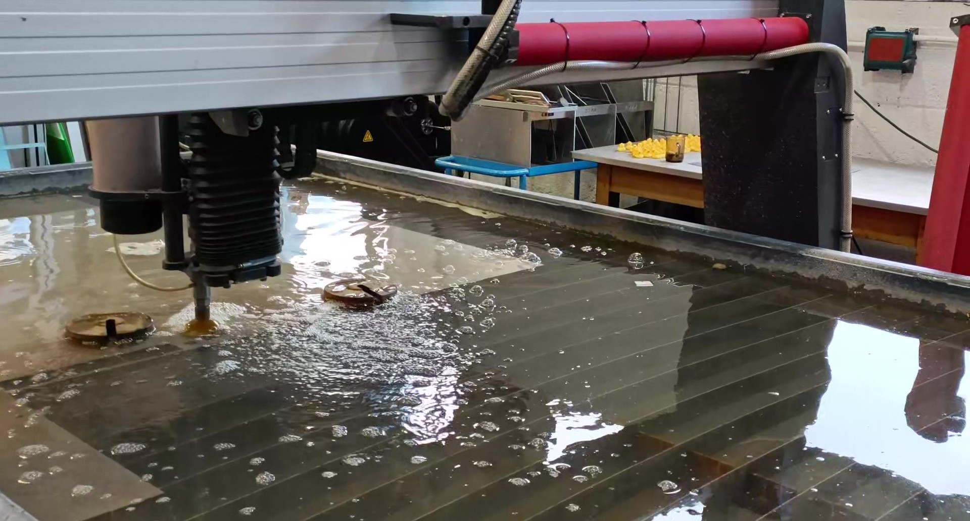
At the same time, the motor mounts were being cut
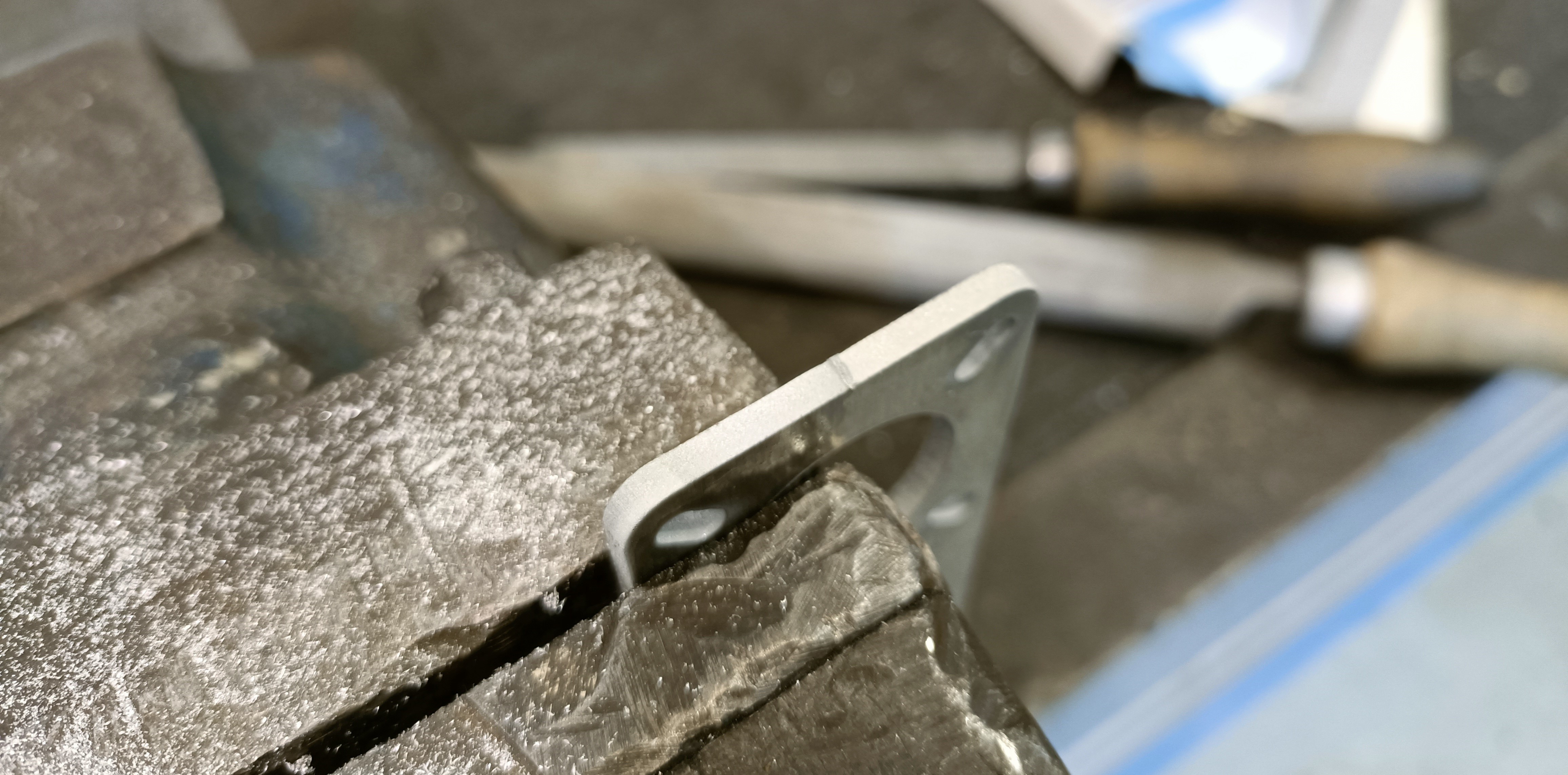
I couldn't see much of anything because of the bubbles. After that was done, I needed to file the tabs that were left behind, as well as debur the edges. One side is notably sharper than the other side.
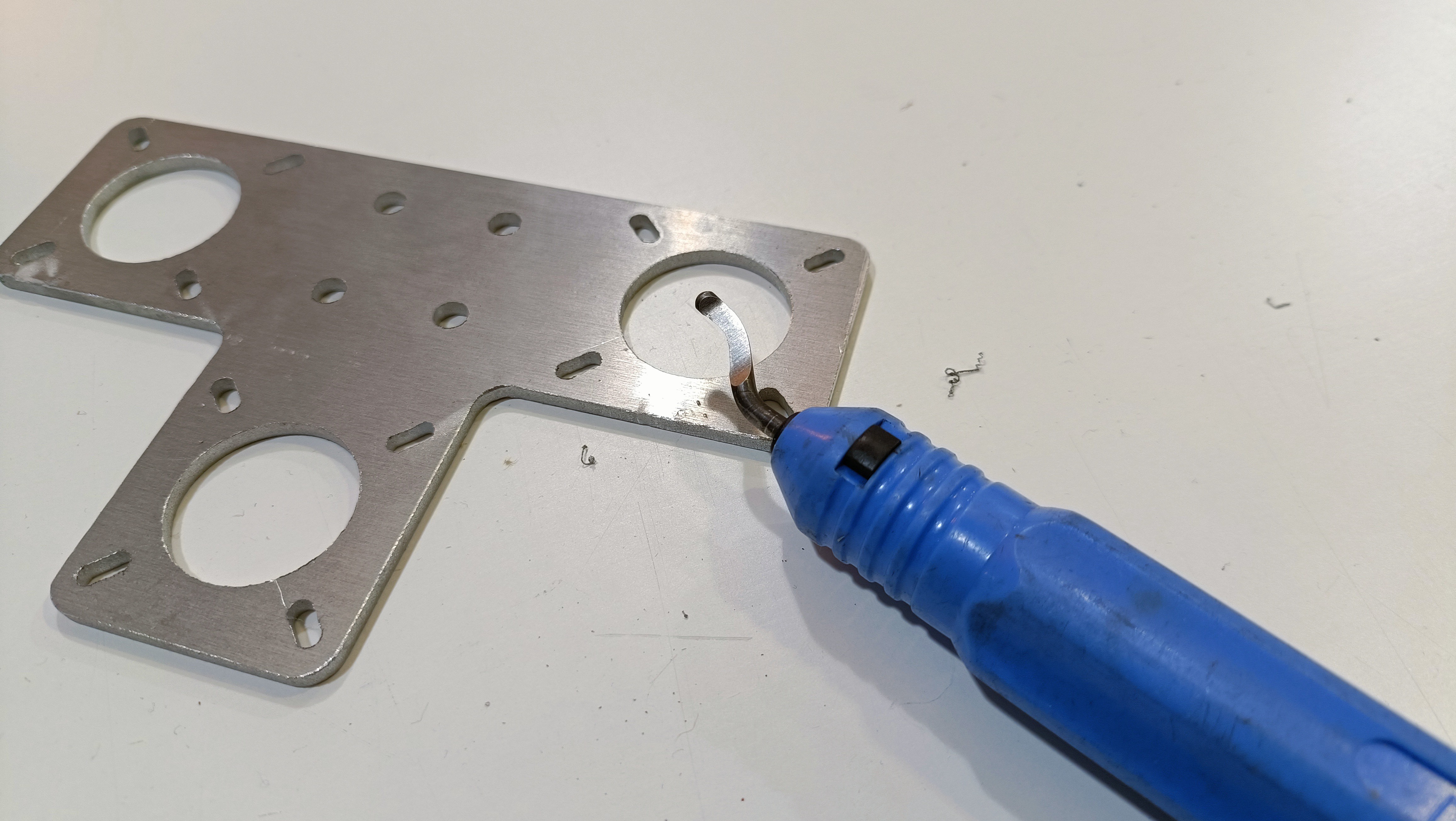
I used the large file to file away most of the tabs and then the small file for the rest of the tab and deburing the edges. This strategy wasn't ideal for the large inner holes, but the uni tech guy just happened to have a handy deburing tool:
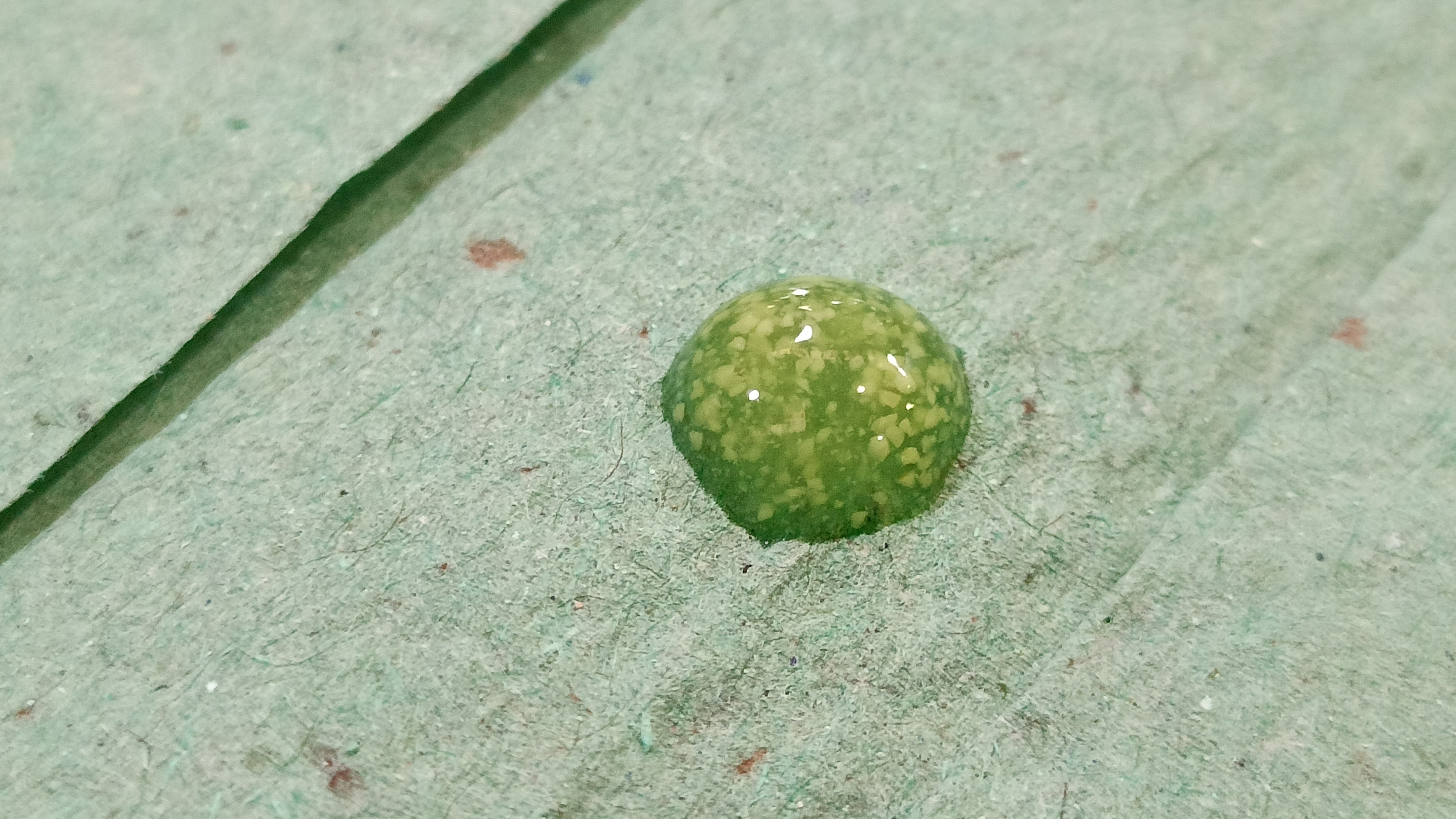
Finally I just had to brush off the parts and wash off my hands. The university workshop happens to have some interesting soap with granules in it:
Dimensional tolerances
The small holes for the PTFE gasket were 2.75mm and the cartridge holes were over 7mm, which was larger than the 2.3mm and 6.7mm respectively I modelled. Theoretically, there shouldn't be any problem with this as long as everything holds up. It also gives me just a bit more misalignment tolerance. I'm just a bit 👀 when it comes to the 2 inputs closest to the heater cartridges because, like with the clamp plate, that is where material is thinnest.
The water cutter tolerances are closer to expected, if slightly undersized.
Other things to mention while I'm here
- The print order is "at 50%", which means that it's actually finished being programmed and is now printing.
- I'm going to get 2x70W heater cartridges because the Coaxial8or is double the volume of the test 4-in-1-out.
- I've switched the pins so that these heaters are run off the bed mosfet.
- I'm going with TMC2226's for all motors because, with XYZ on the BTT Motor Expansion, those axes now get their own dedicated DIAG pin (for sensorless homing) instead of having to share with endstops.
- Technically, I could just tweak the endstop positions on a normal board configuration
- I'm going to try this PTFE sock from FysetC to hopefully prevent material from sticking to the nozzle when testing
-
[M] CR600S+coaxial8or logotype and numbers
02/25/2024 at 19:59 • 0 commentsI've spent the past 100 minutes designing number characters and then using some of those to make the CR600S logotype.
I like how the CR600S logo has 6 dots and, together with coaxial8or, there are 8 in total! I can't say I planned for that. The numbers are for the TFT screen idea. Out of all the numbers, I'm least confident about 7:
Seems to work ok for most numbers, like 27 and 37, but not 17. Hmmm maybe it's the 1 that's actually the problem here.
It's a bit annoying that 1 and 7 look so similar. I'll just stick with the more circular design.
[Feb 27] I've come up with a 1 that I think is OK enough:
Coaxial8or [gd0144]
Full-colour FFF? Multi-materials with unparalleled interlayer bond strength? Abrasives without abrasion?
 kelvinA


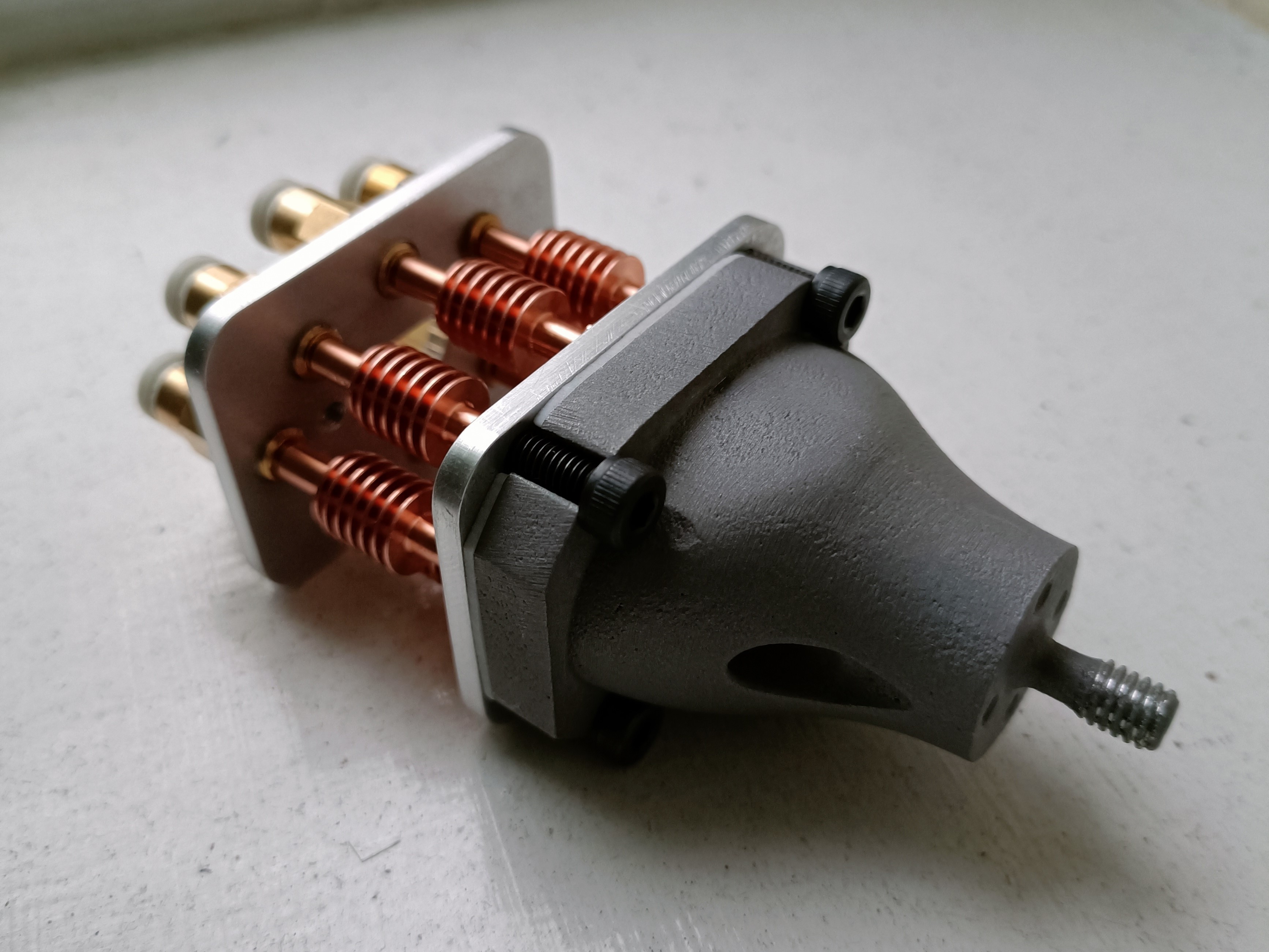

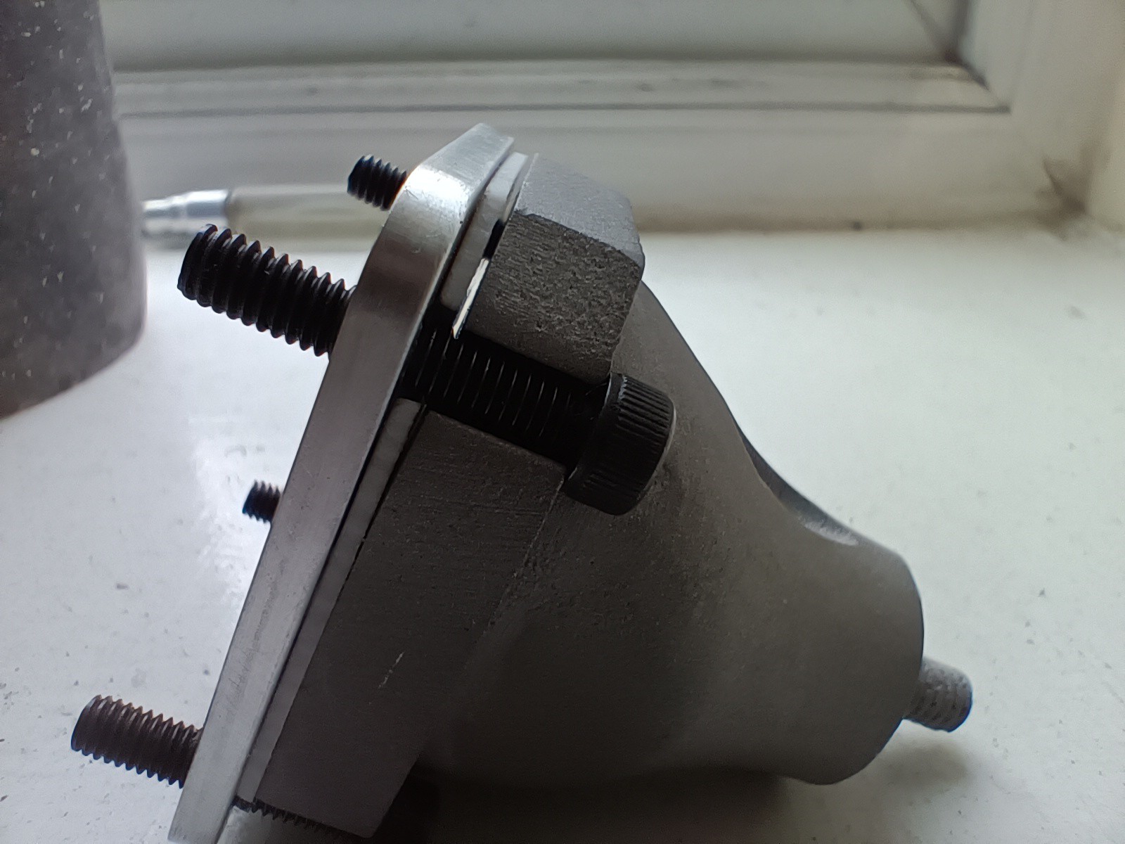 This is the clamp plate, gasket and heatblock all together, and the non-flatness is visible. If the screws are tightened, the 3mm clamp plate understandably bends to conform to the unlevel surface. I'm probably going to play it safe and ask around to see if I can get it lathed / sanded flatter.
 The university happens to have a wide variety of manufacturing facilities.