Started with charge pump as it was most tricky part in my opinion in power supply circuit.
Other power supply components I've already worked with such as LM7805 and they are pretty straightforward.
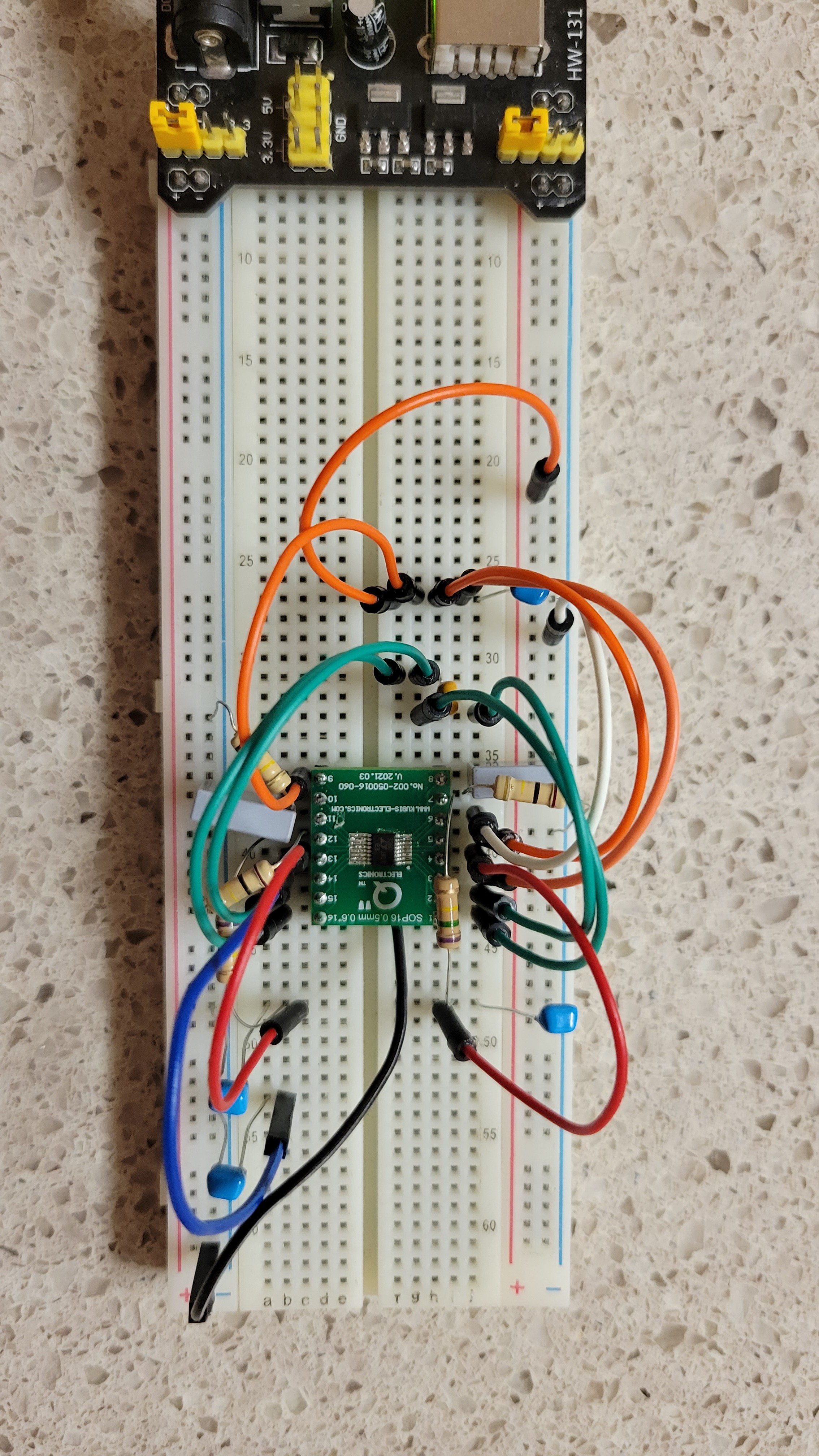
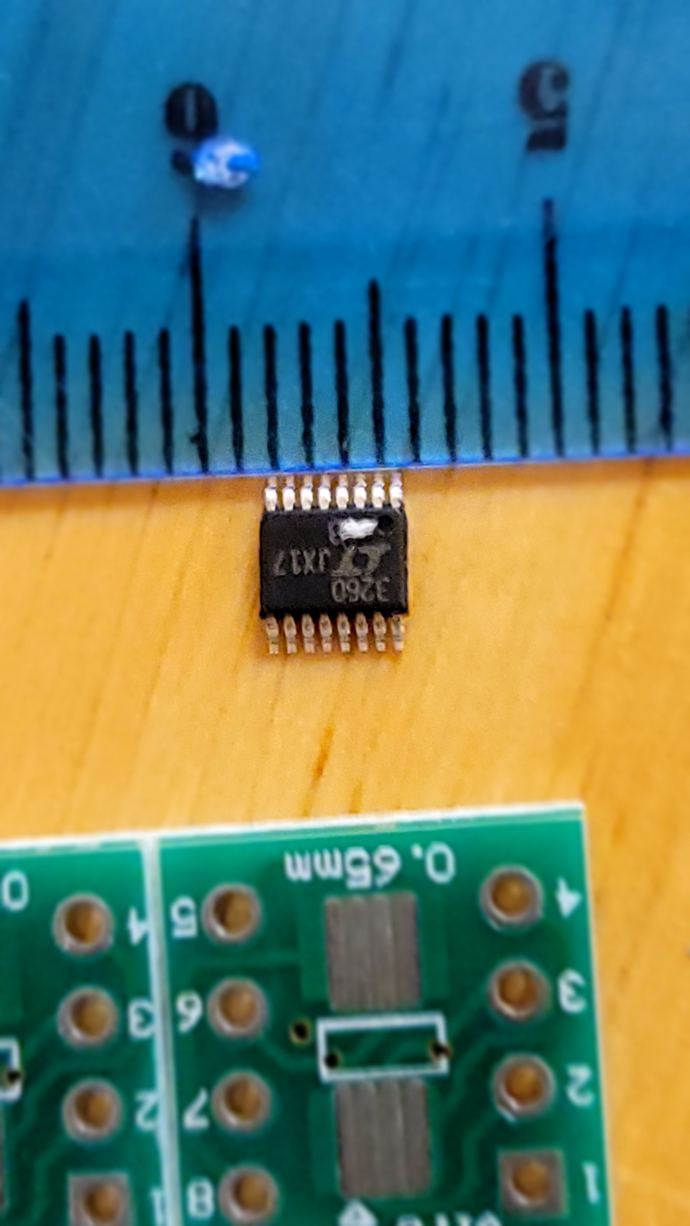
This oddly looking thing is the LTC3260 with all capacitors and resistors connected
And the result is negative voltage compared to GND.
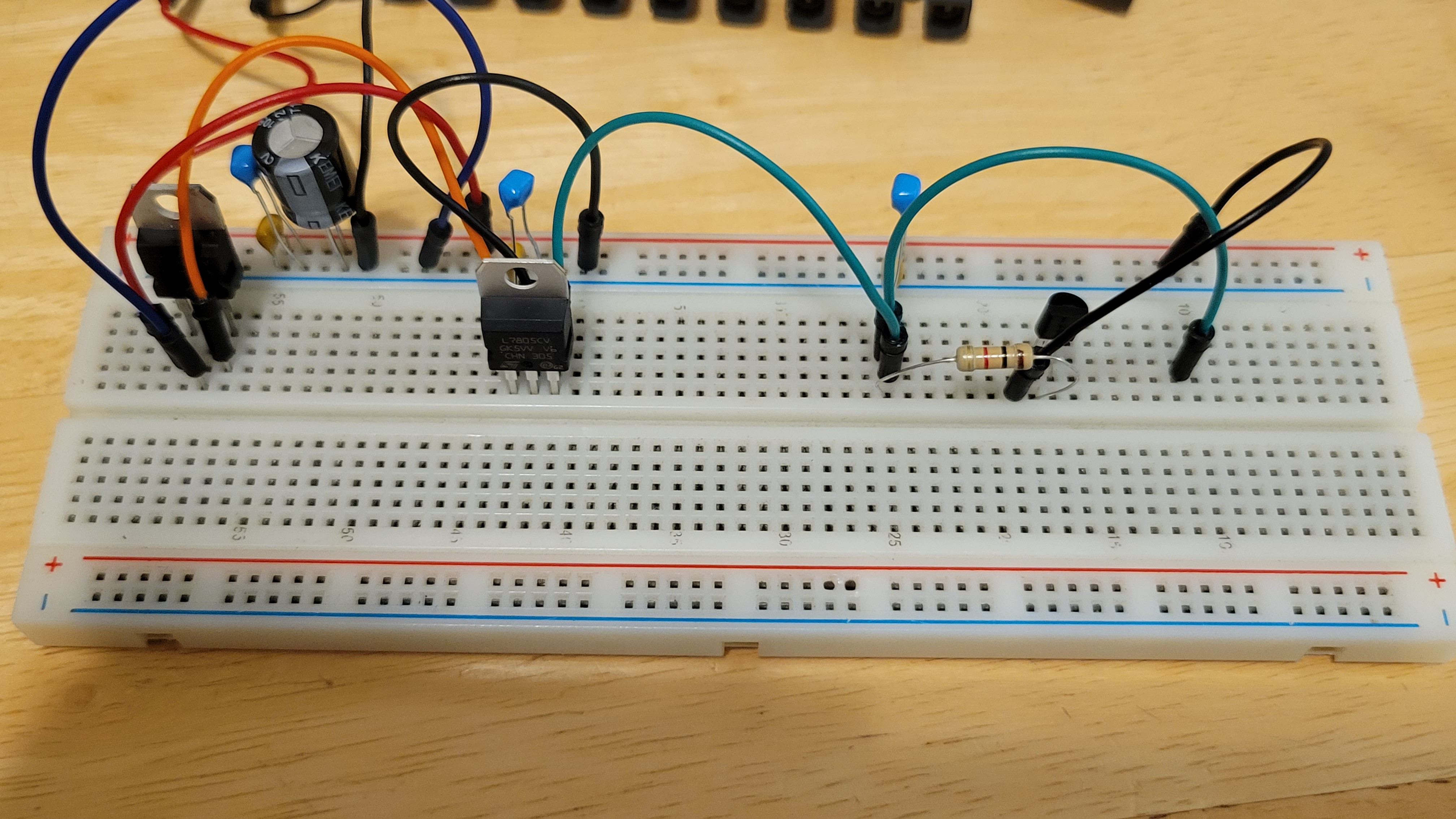
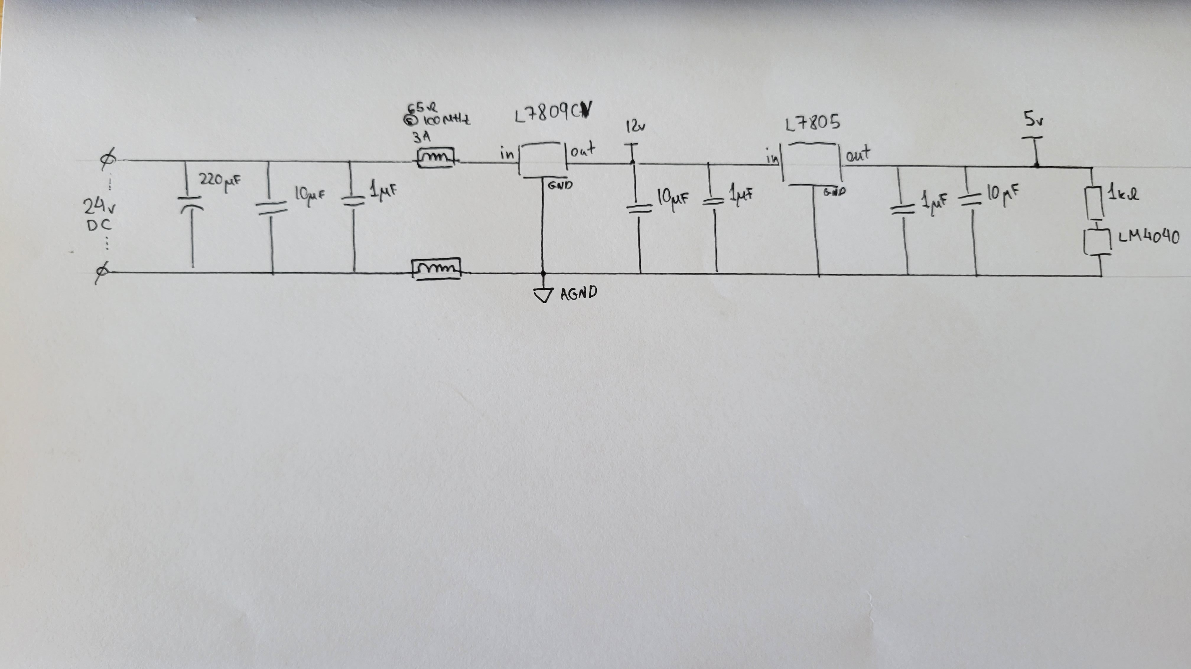
The next steps are creating downsteping from 24v to 12v and 5v.
As expected it was quite straightforward
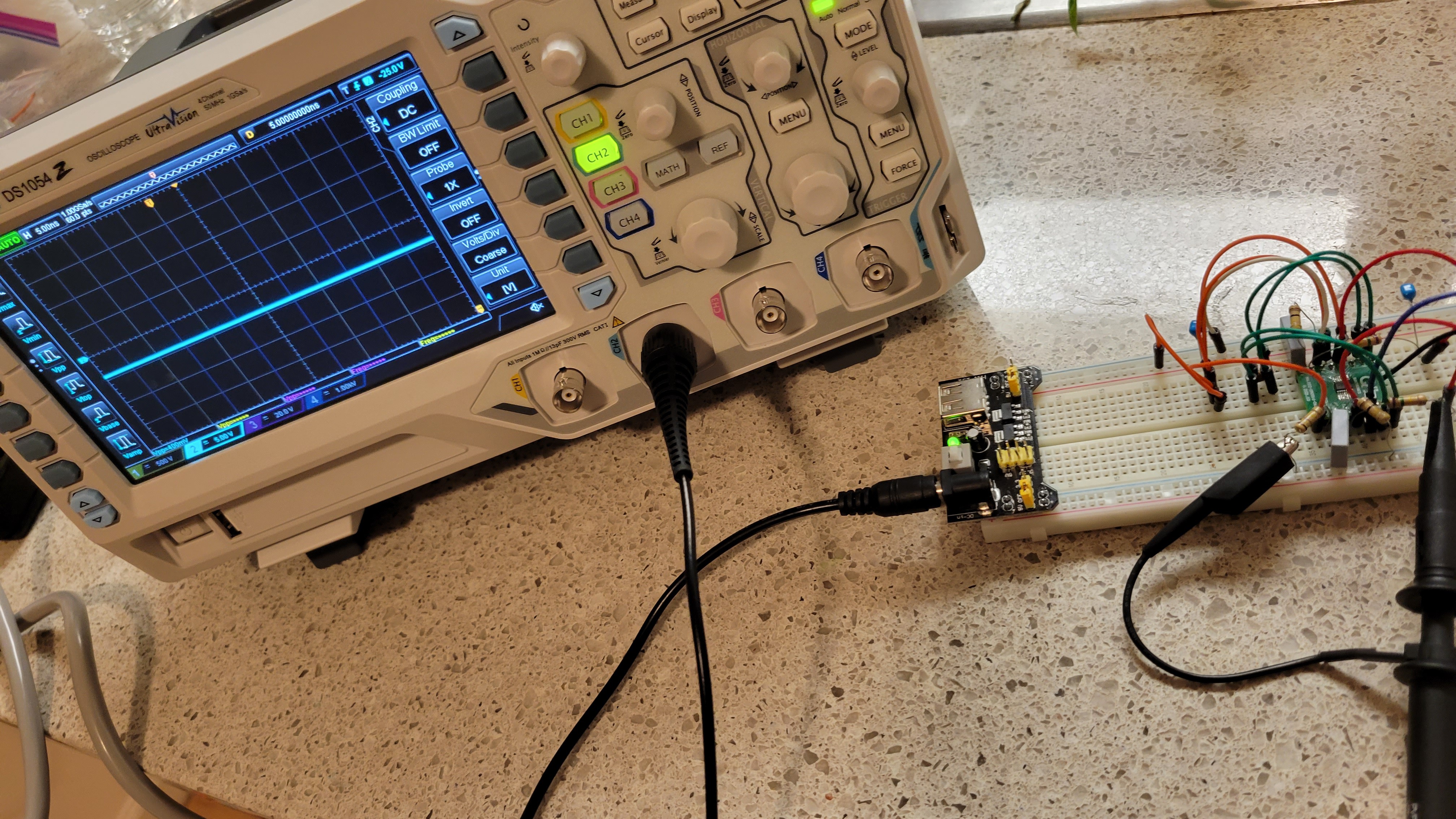
In my case it gets 24v DC and convert to 12v DC and 5DC.
The outputs of 12v and 5v seems very flat signals, although I am not quite sure how to measure it.
Well that's is another milestone
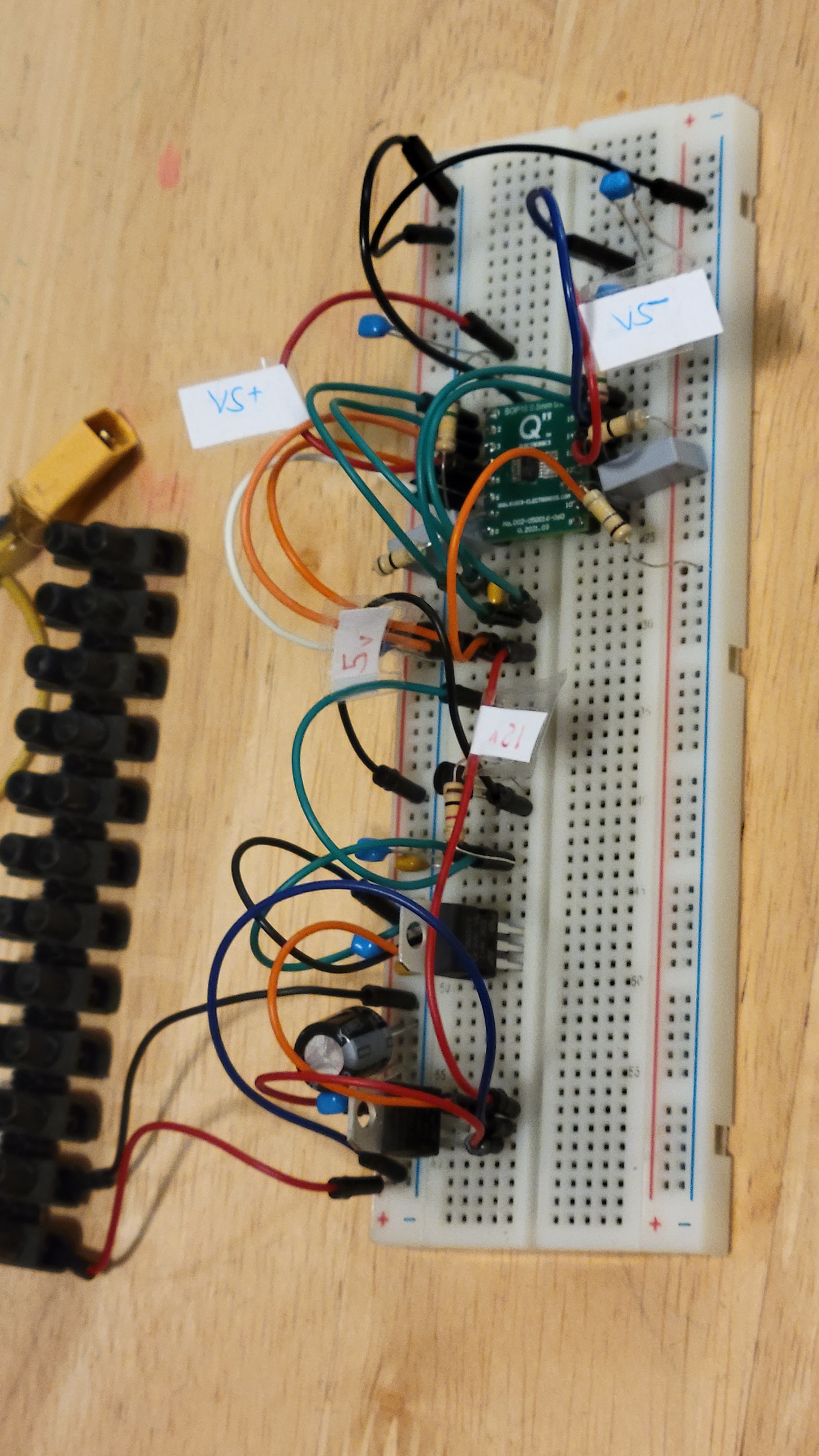
Since there is a lot of space on this bread board I thought to dense both the power supply and charge pump. This way 12v, 5v, and -12,12v from the same board.
Got the components but it turns out that they too small to work with. My CNC machine cannot go beyond 1mm resolution.
So now waiting for converter from 0.5mm to DIP-16, from Poland.
My first try to solder this tiny components ended up by soldering all together 😕 but second was more successful.
TADA 🎉 !!!
Now I can proceed to building the power supply for this project.
Not so fast...
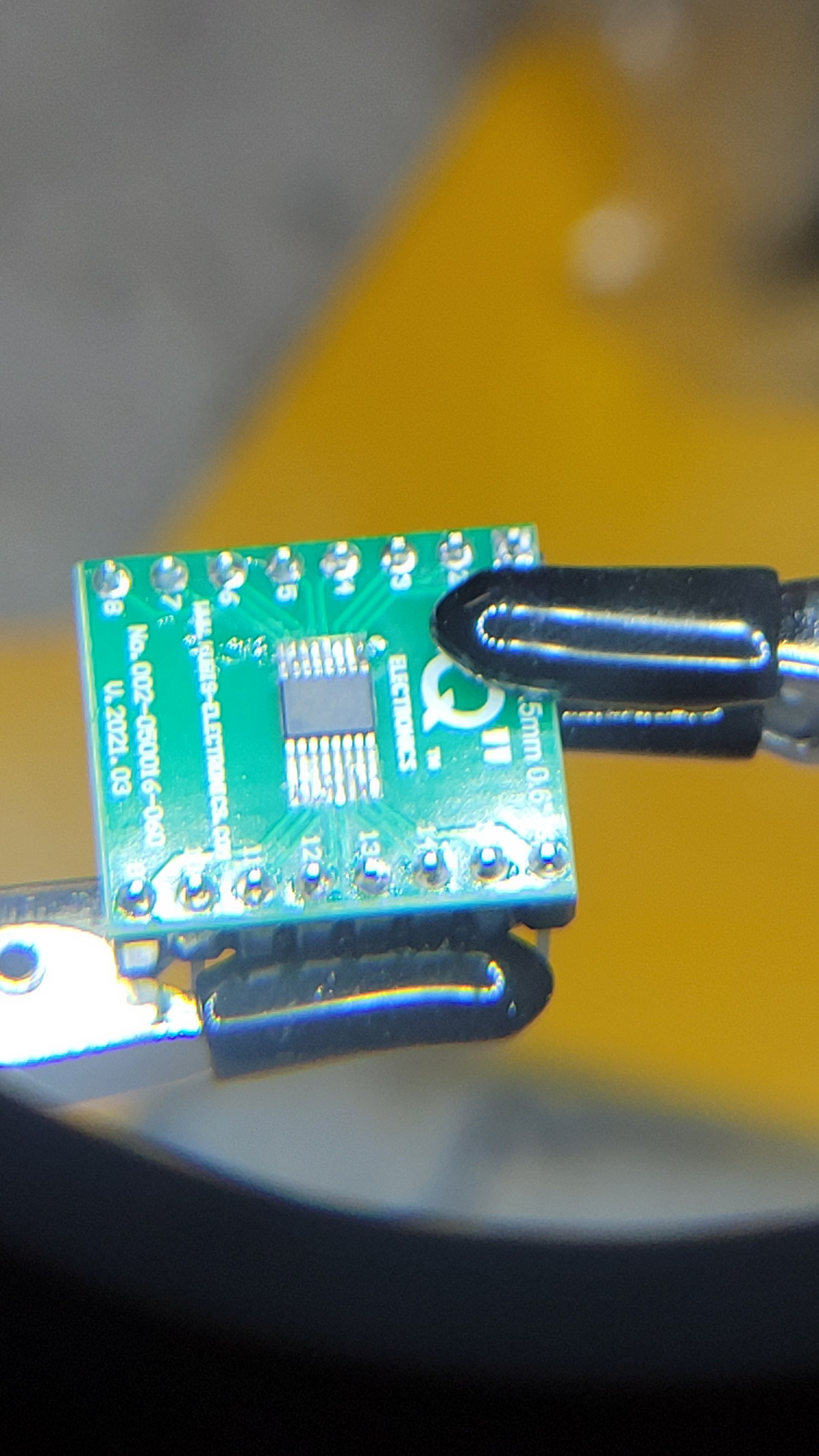
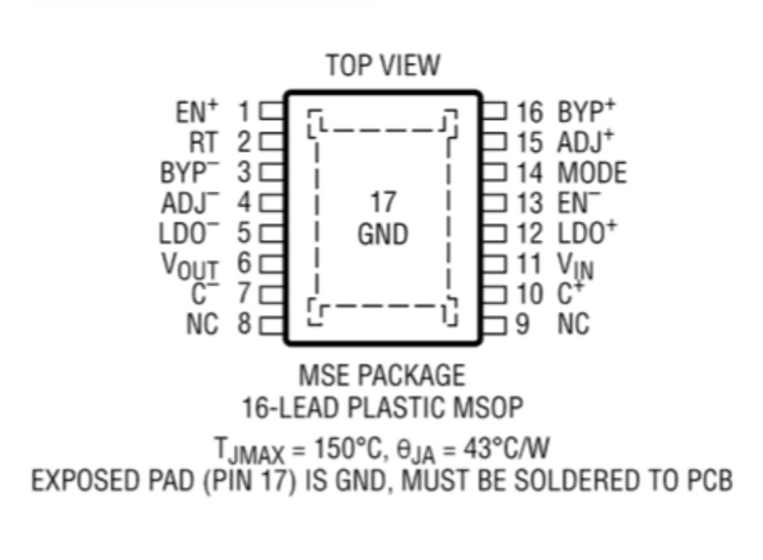
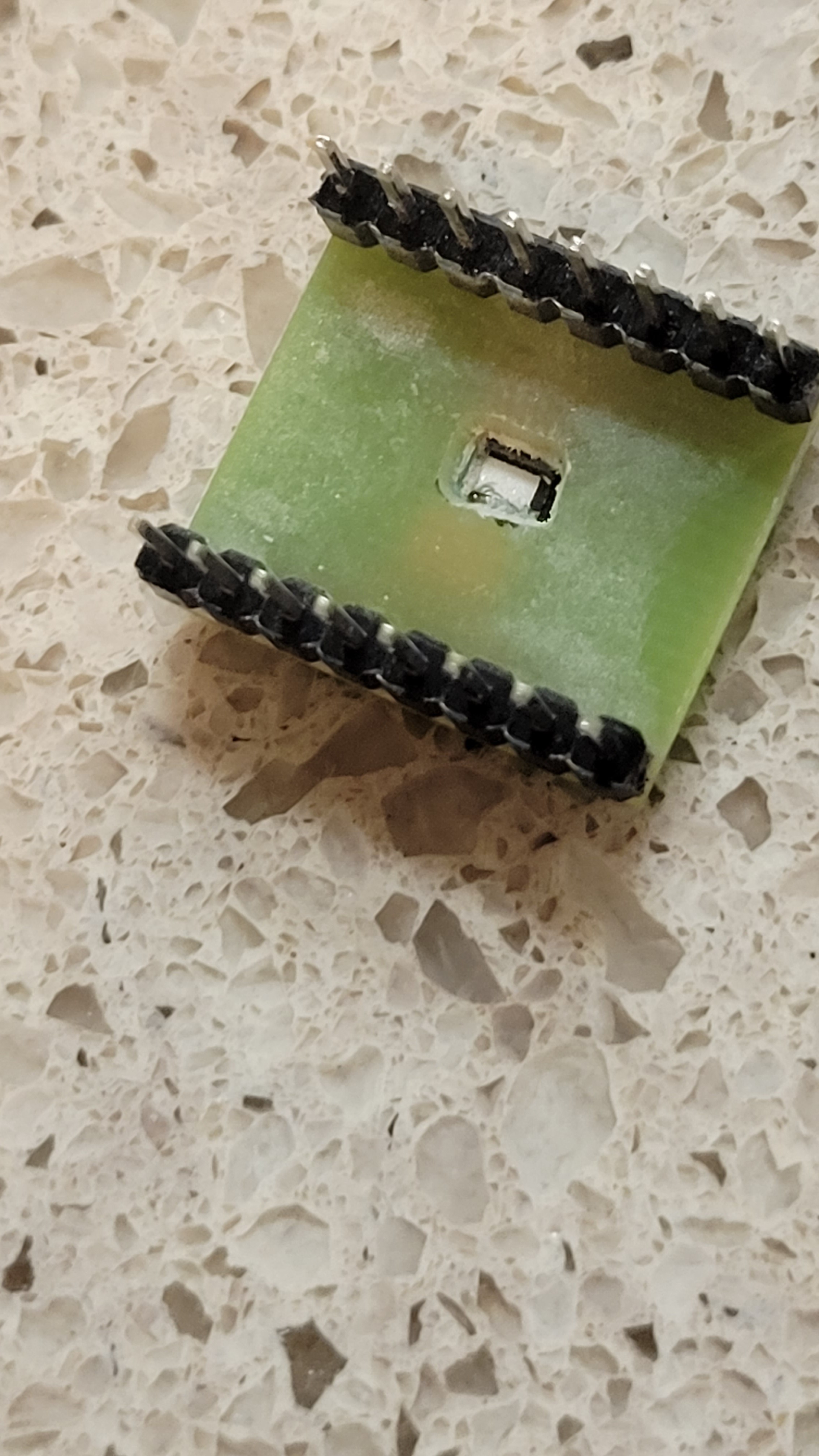
I was trying to connect this IC to the 5v and I couldn't find GND terminal. What?!
It turns out that GND is underneath the chip. I could resolder it but the connector doesn't have GND pad. I guess I should make a hole in the connector PCB and connect. This is another setback.
I guess I should find the components by myself but this reference got lots of good ideas. I guess it worth the pain.
Luckily I have CNC machine, after gently curving through PCB I got this
The GND terminal is exposed! Hopefully I didn't break anything in the process.
One of the reasons I feel this project is feasible is some nice open sources. One of them is OpenAFM, it holds lots if valuable information like electronic schematics. It's power supply and piezoelectric controller looks interesting. It took me time to find the software which will conver schematic to eagle files. I got those:
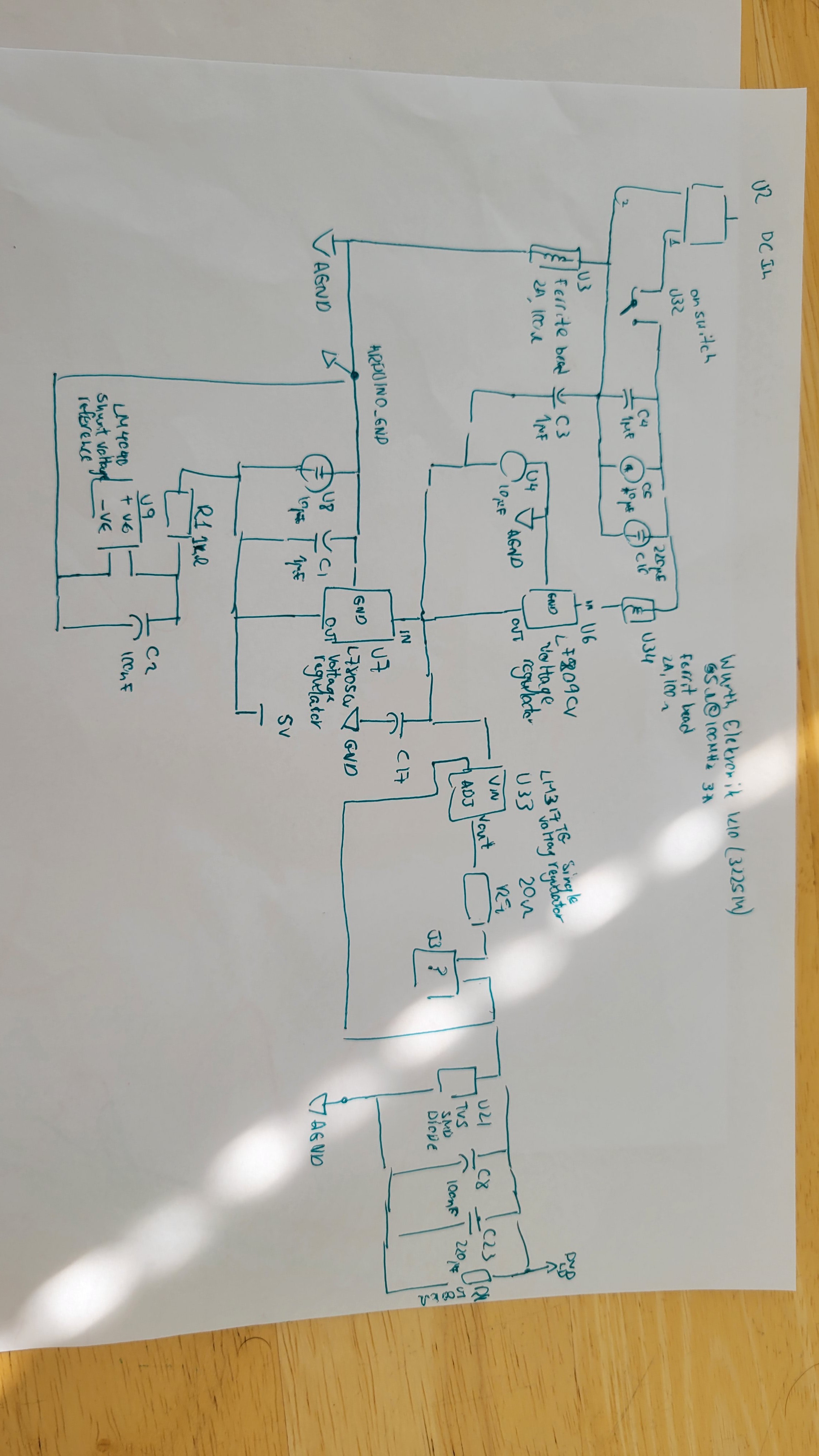
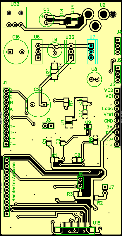
Power supply board
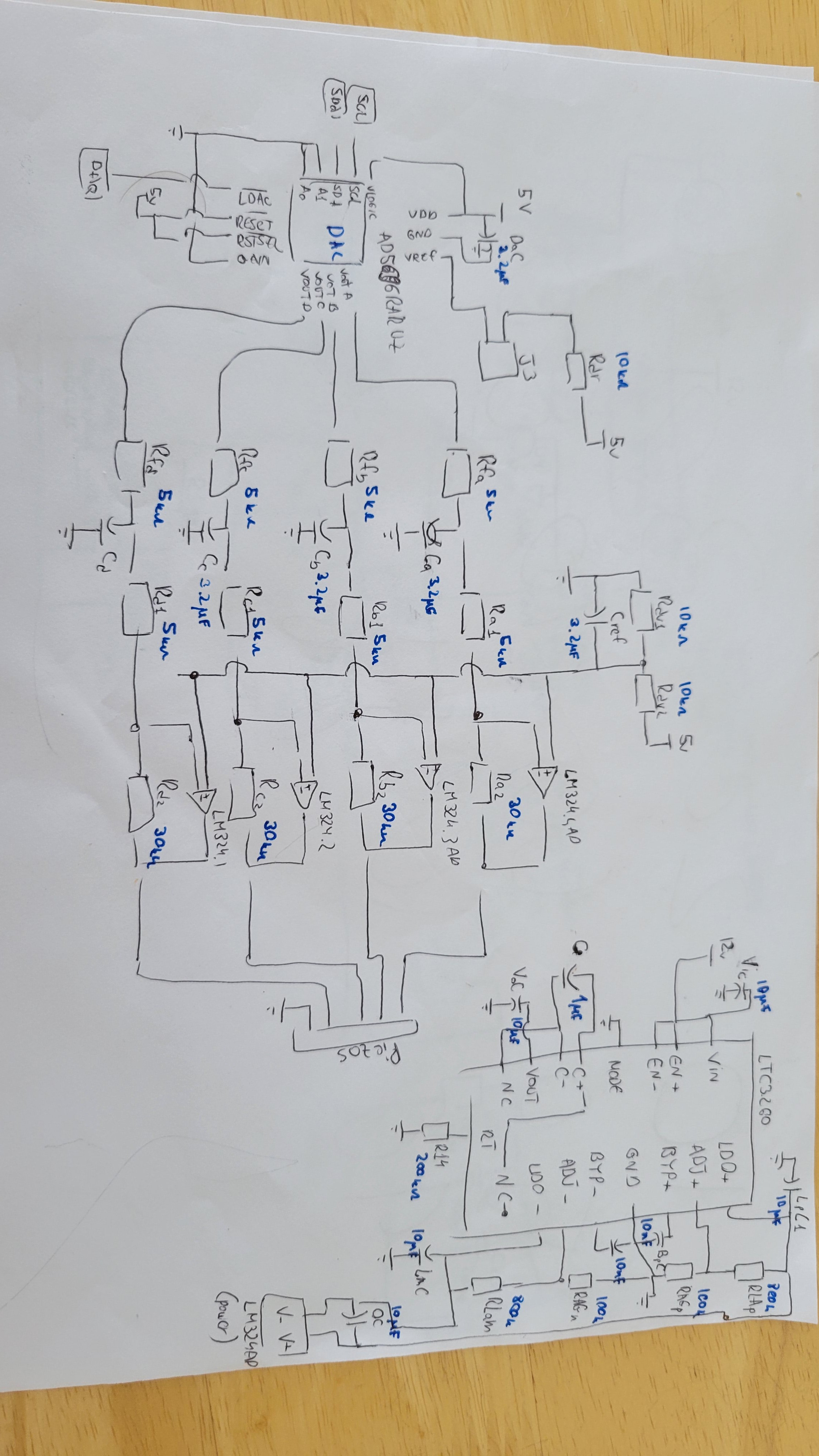
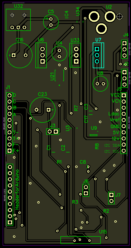
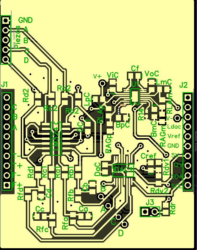
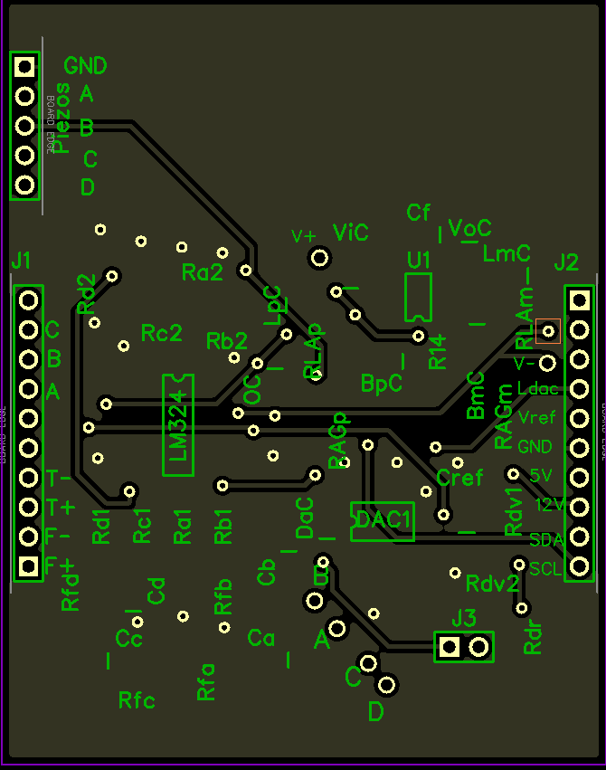
And piezoelectric controller board
Now it's only to buy all the components and try to connect them. Fingers crossed 🤞
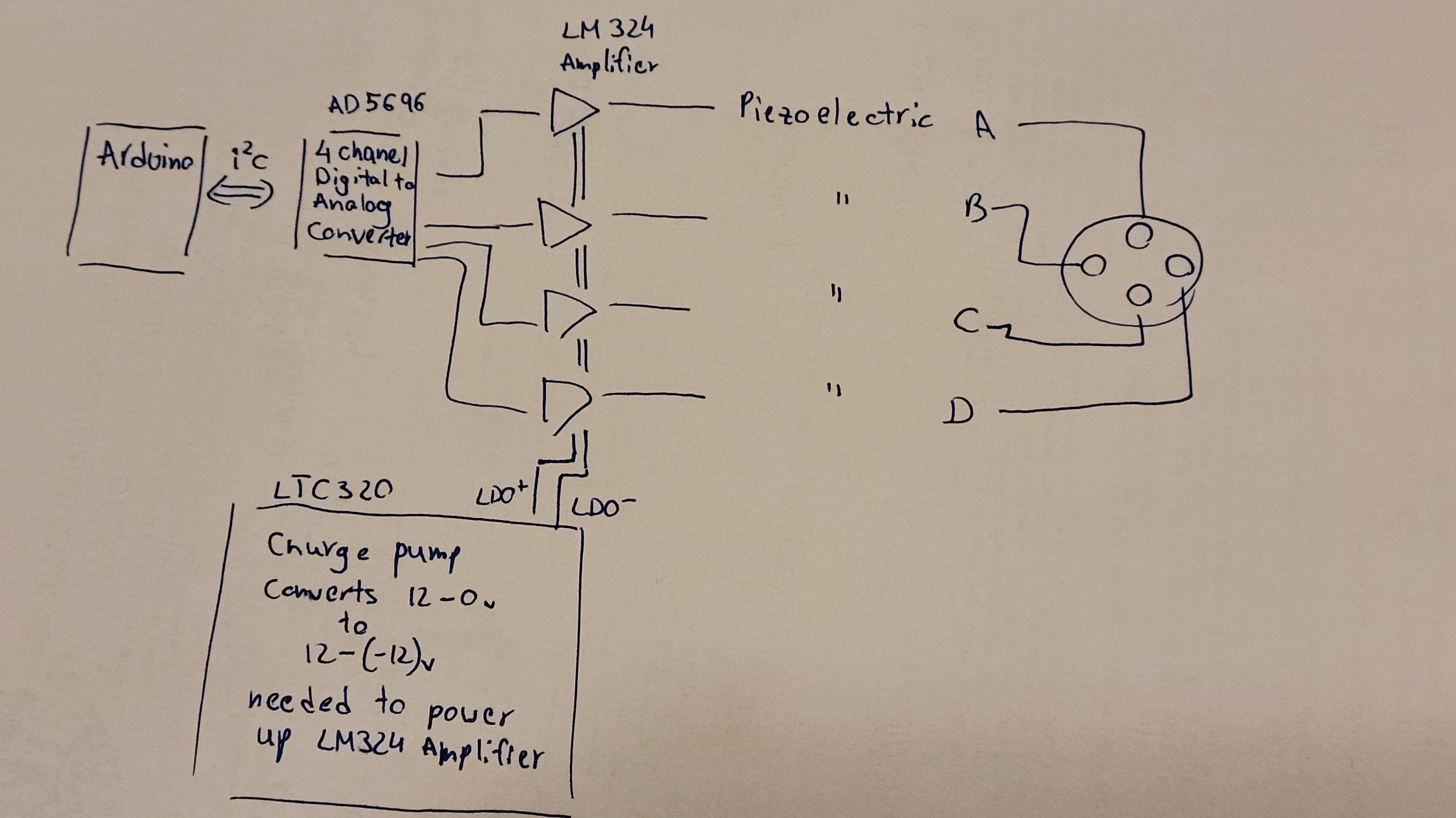
Although it might look scary a bit at first but after some researching the components and you get this simplified schematic
Some pictures from openAFM (converted to Eagle files)
This will help to reduce noise in the final layout
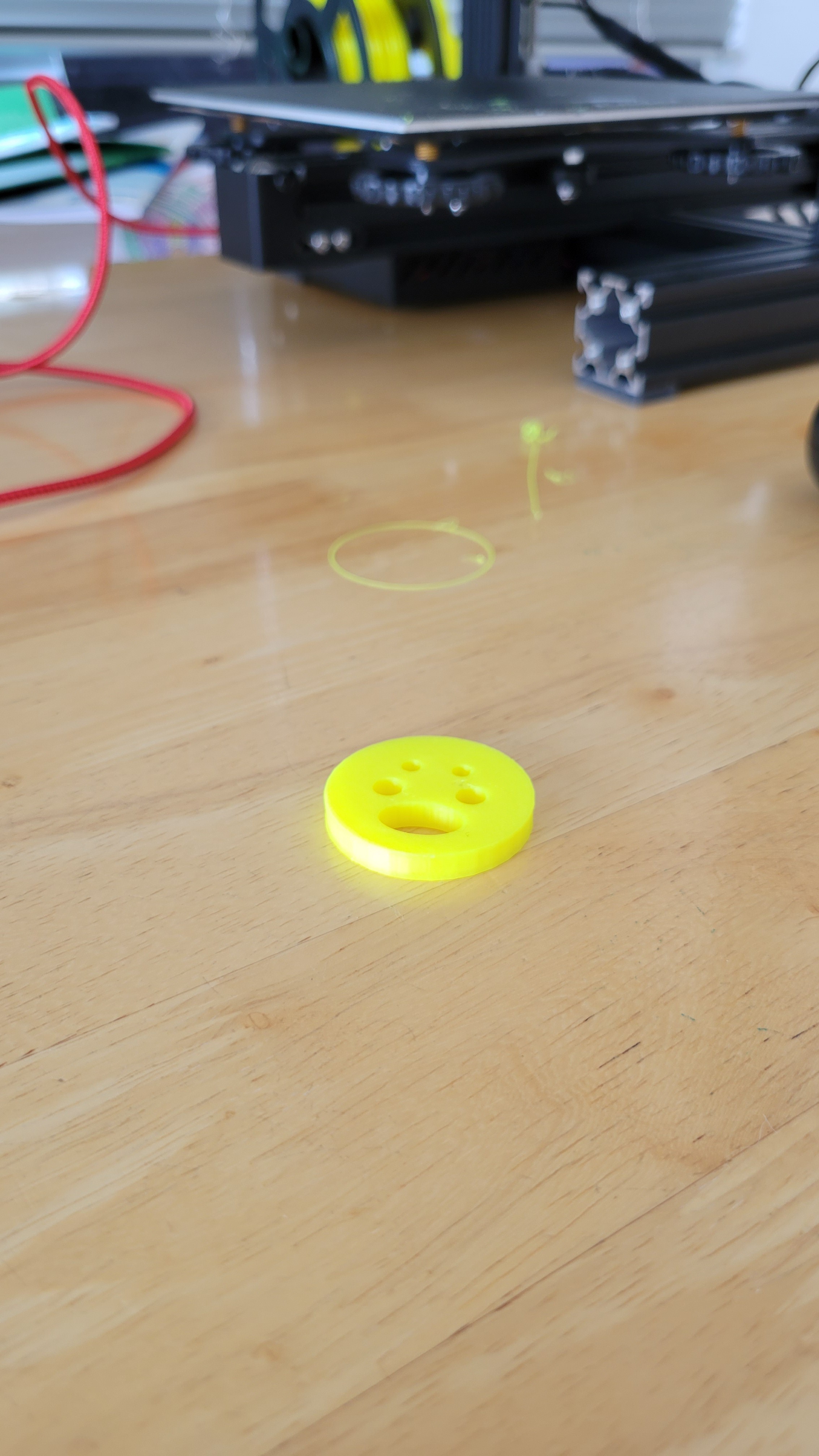
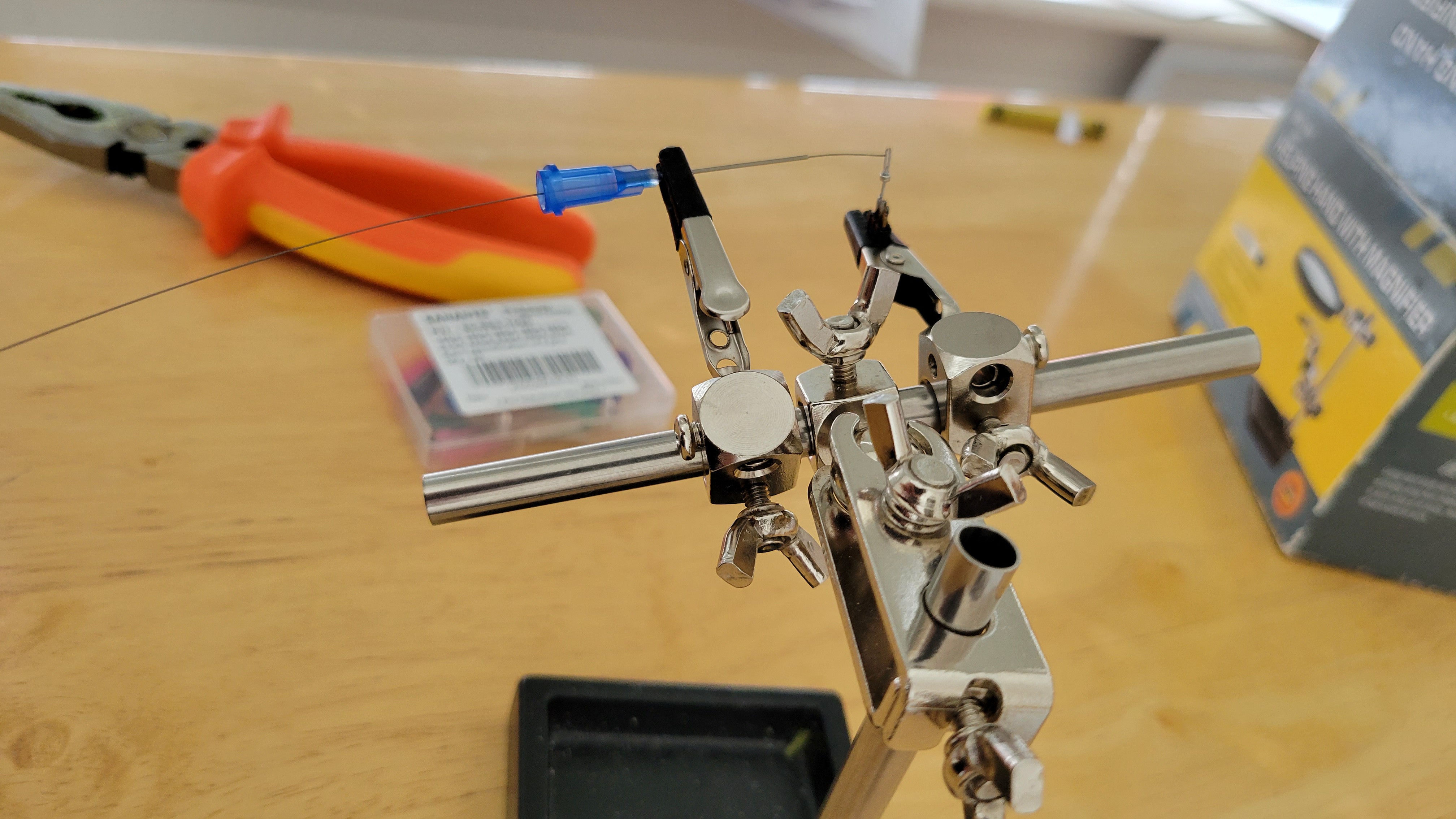
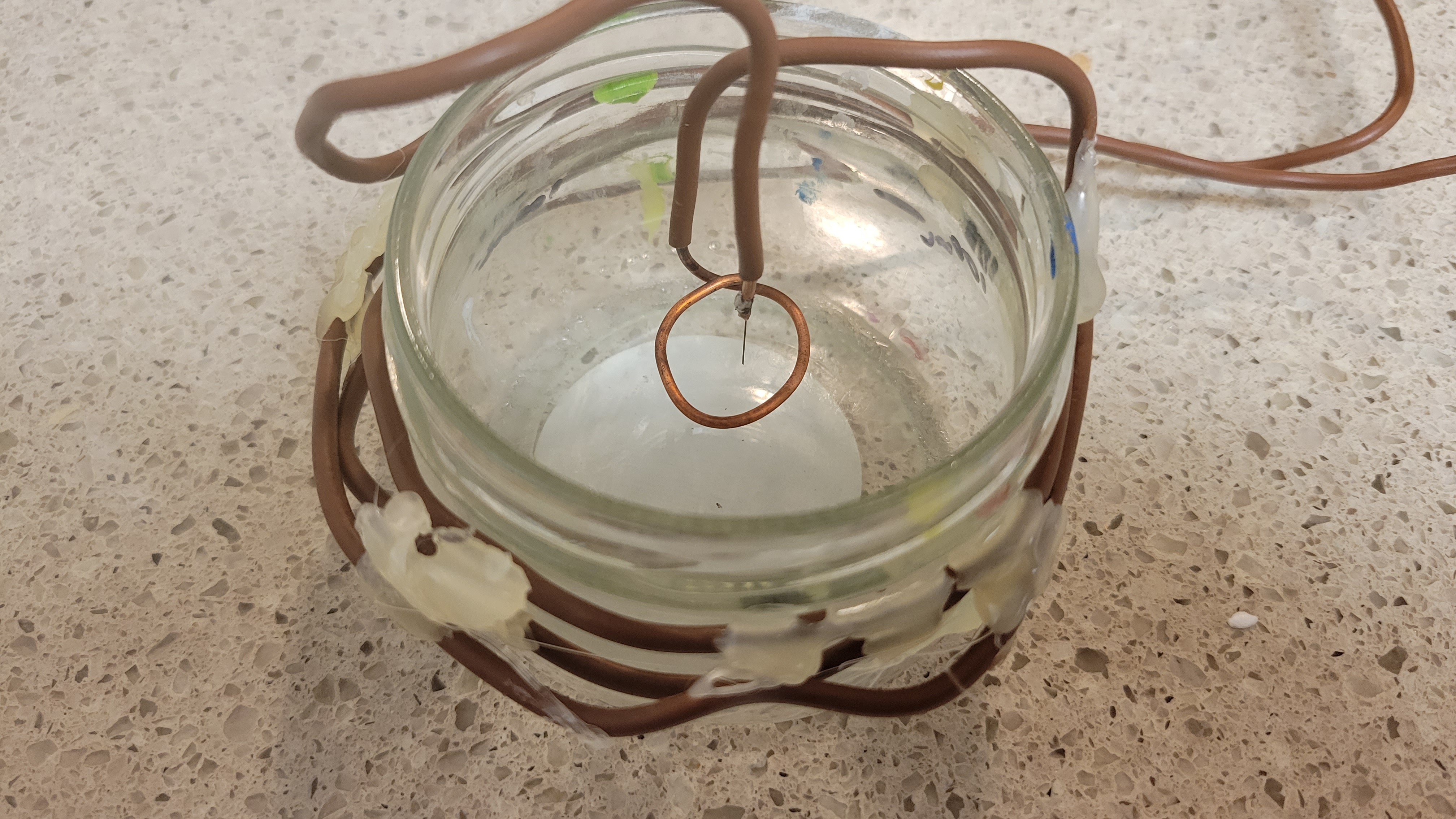
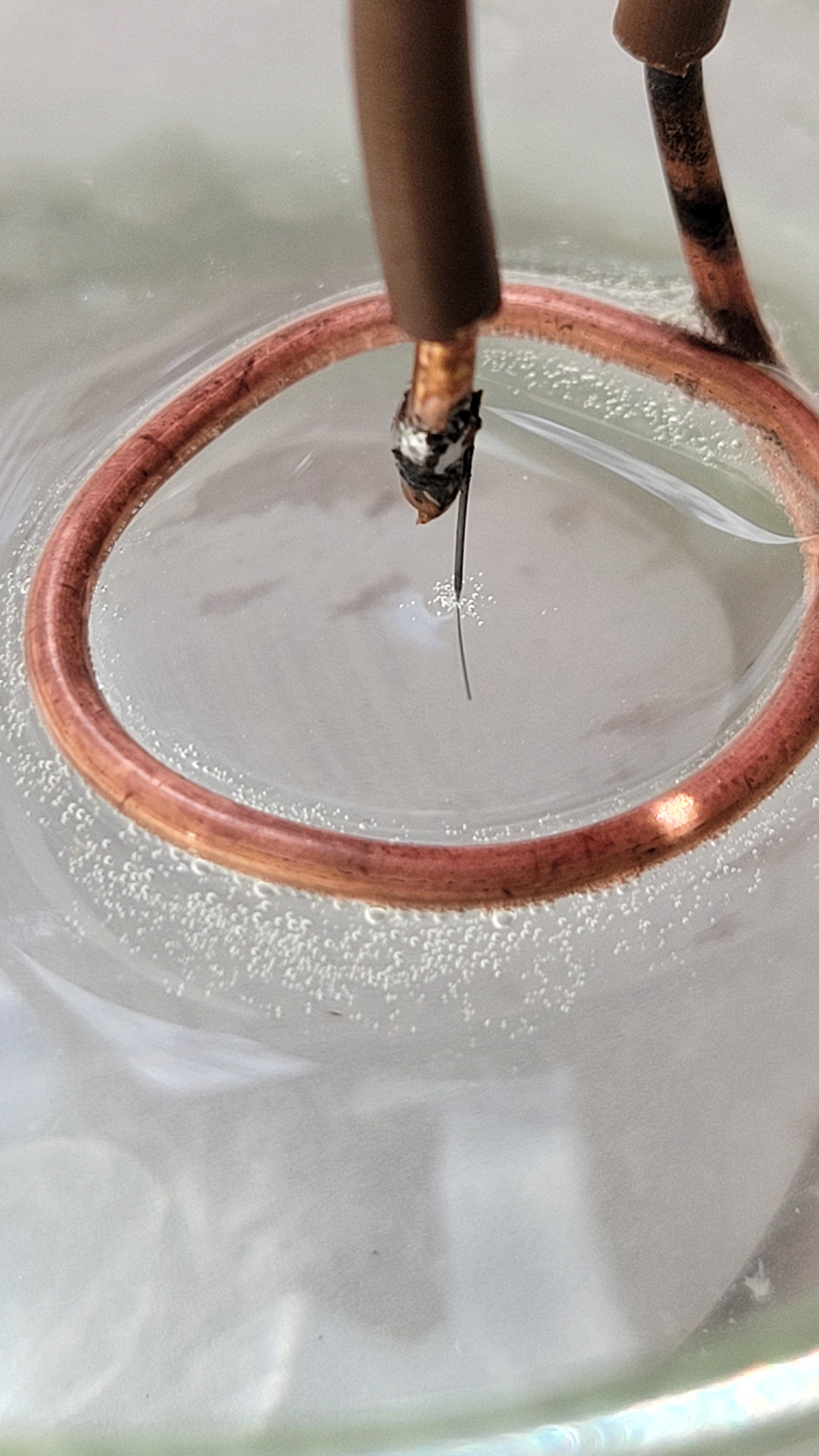
One of the problems with my prototype was that the wires were hard to bend into the right position. Now I made this assembly to hold everything in a much easier fashion and use suspended ring. Another reason is this configuration doesn't require Tungsten wire to be connected to as cathod, thus we can make it extremely short while it's connected to Quartz tunning fork.
The idea is to have a springs, by pushing springs down get solution into the small ring.
Once the Tungsten wire snaps it will cut electric current this making the tip much sharper (in my previous design I had to stop the current manually. This short time might de-sharpen the tip)
It should run like this
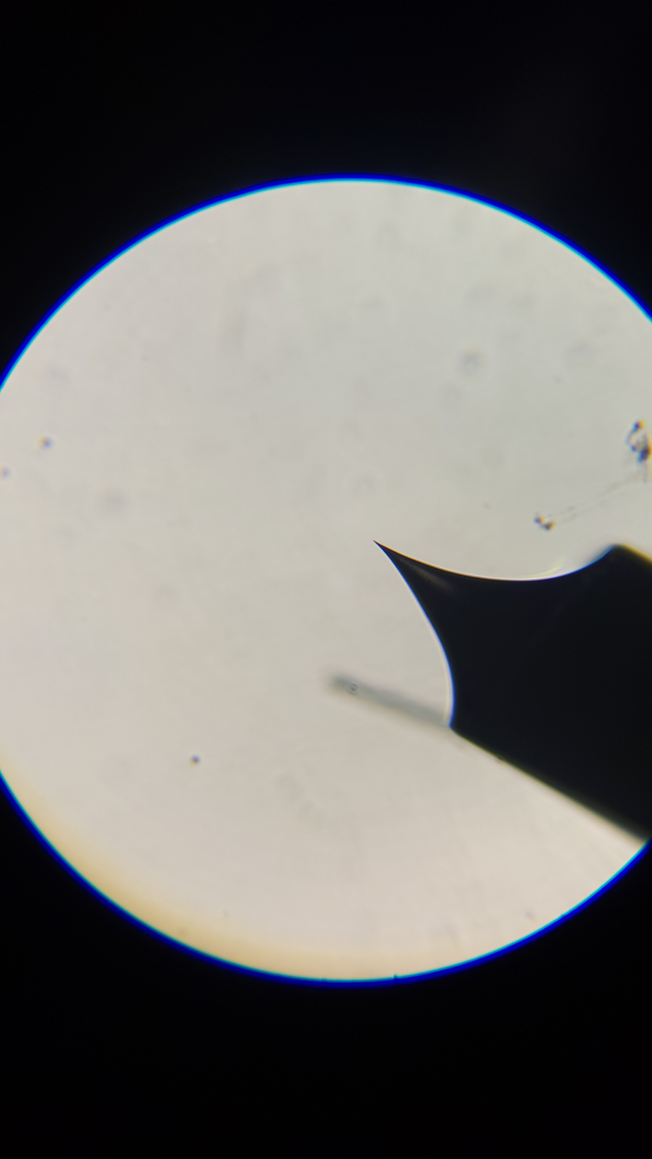
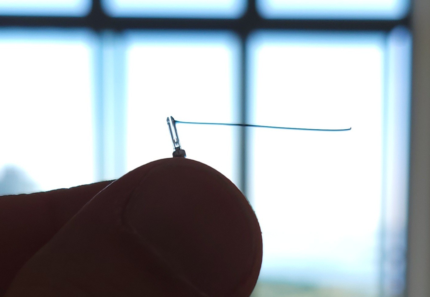
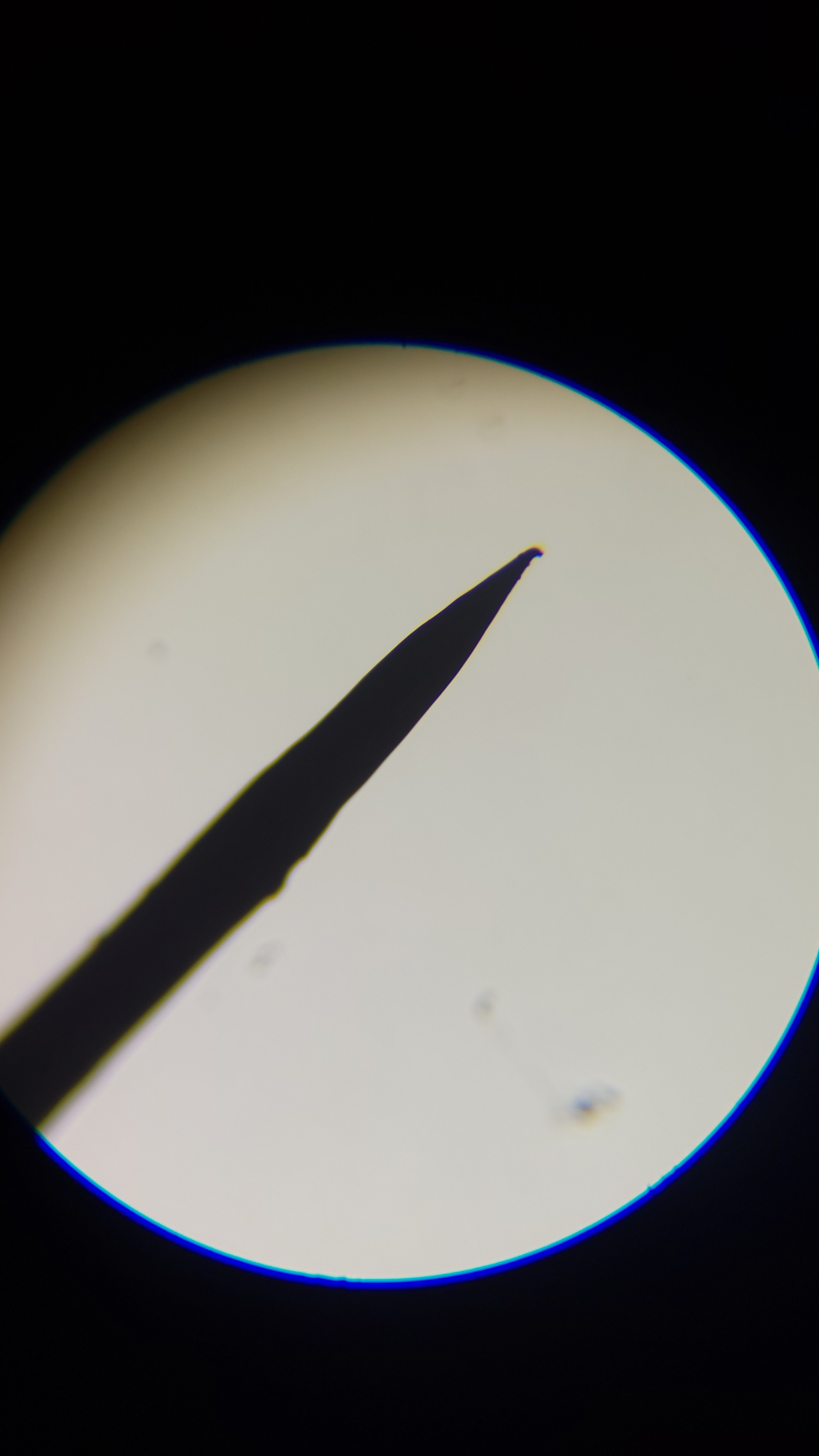
And the result is (after about 90 minutes)
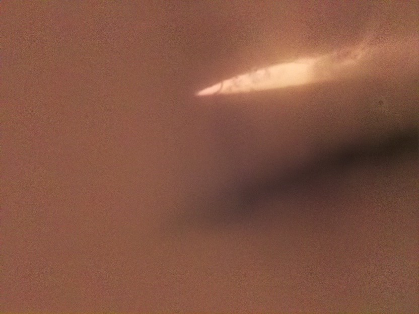
Again I've managed to bump (twice) this sensitive needle into the ring(after I've crushed quartz fork)[Sometimes I am a disaster]. As a result the tip was bent. But we clearly can see the tiny tip much smaller than my previous one. Actually this is a design problem. The ring is held by lower holder and the Tungsten on the upper. I should redesign so both the ring and Tungsten holder are attached to the lower part.
It's hard to admit but this time I think I got stuck.
I think this is one of the hardest parts except building the Tungsten needle.
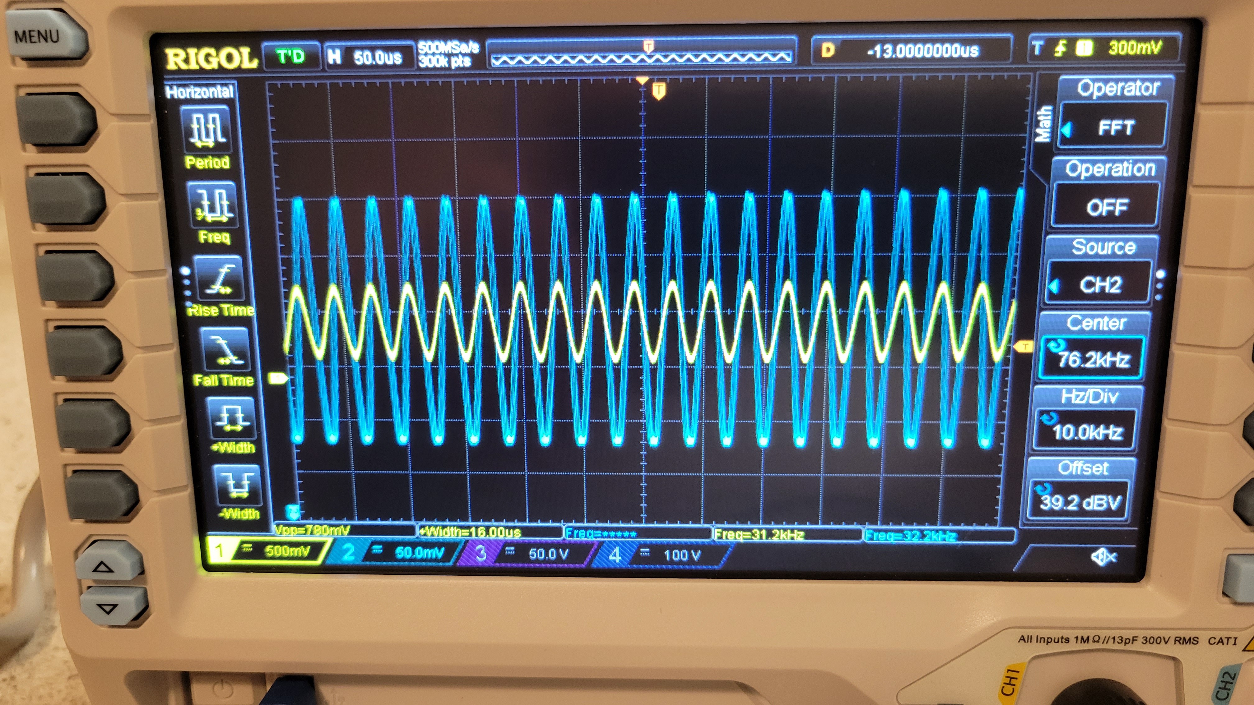
Well the good news is that I was able to run Quartz crystal fork. Using AD9833 signal generator and NE5532 based attenuator.
The yellow is 32.000KHz AD9833 signal and blue is QTF 32.768KHz. The problem is once QTF encapsulation removed, signal disappears. The next step would be using two rail power supply and more sensitive electronics. So yeah, I guess I will have to use LTSPICE to debug it. (It much faster than buying bunch of components and trying to debug it)
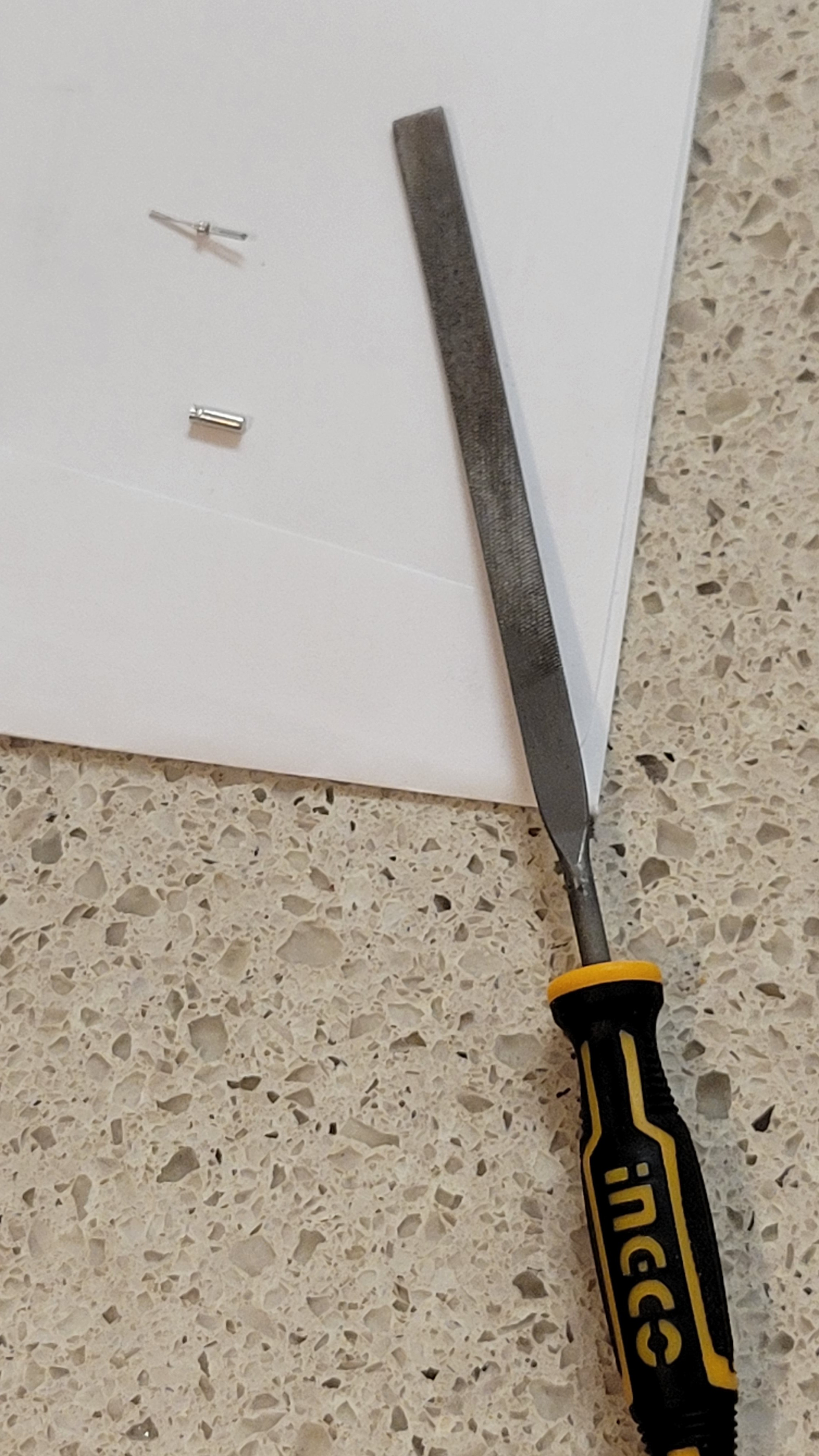
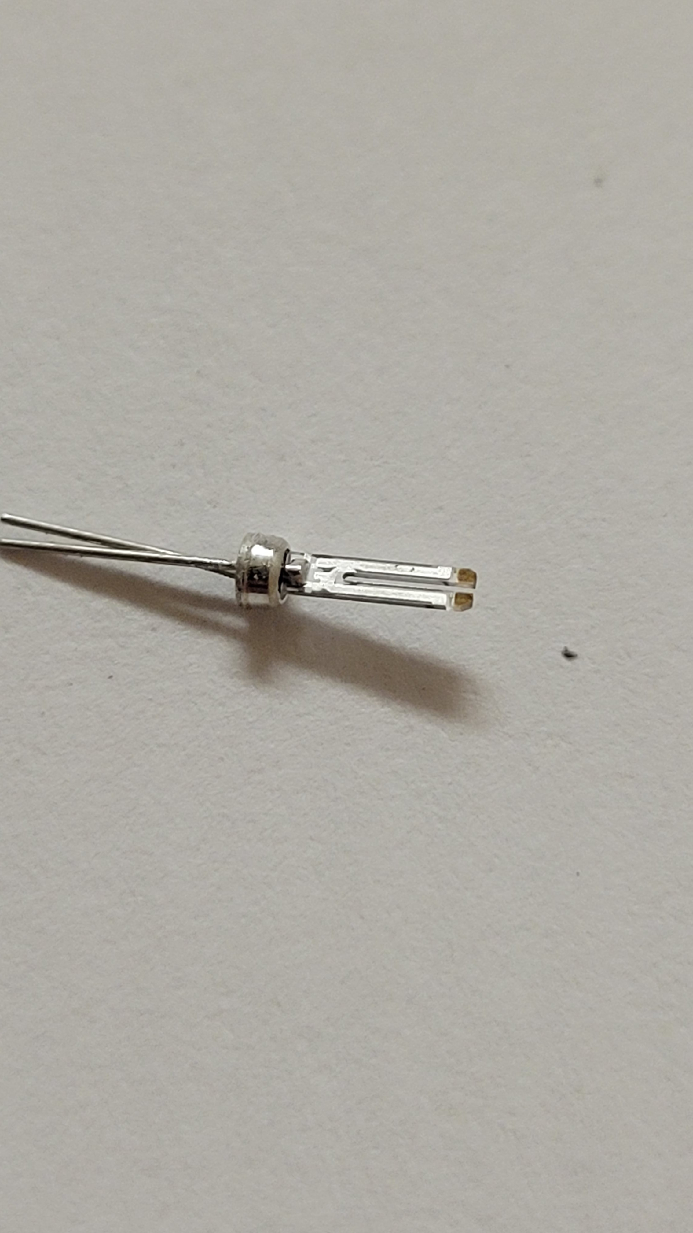
The next step is to use Quartz fork. I've bought sime 2x8mm 32KHz Quartz oscillators. Now the tricky part is to gently remove enclosed without breaking the Quartz fork. I've preferred to use small file to remove metallic encapsulation. (Although it's tempting to put Quartz fork into something like a drill, I was afraid that centrifugal force will damage this tiny fork)
You can buy nanometer tips but they are pricey. Each tip costs about $100 and you must buy a pack of ten.
I would like to go some other way, much cheaper. (As I don't know if I could make one)
The cheapest way to fabricate AFM-tip is using Tungsten wire and NaOH solution.
I bought 100mg of Sodium hydroxide (NaOH)
100ml of tap water and 8mg of NaOH(two tea spoons), and we have a solution, yeah!
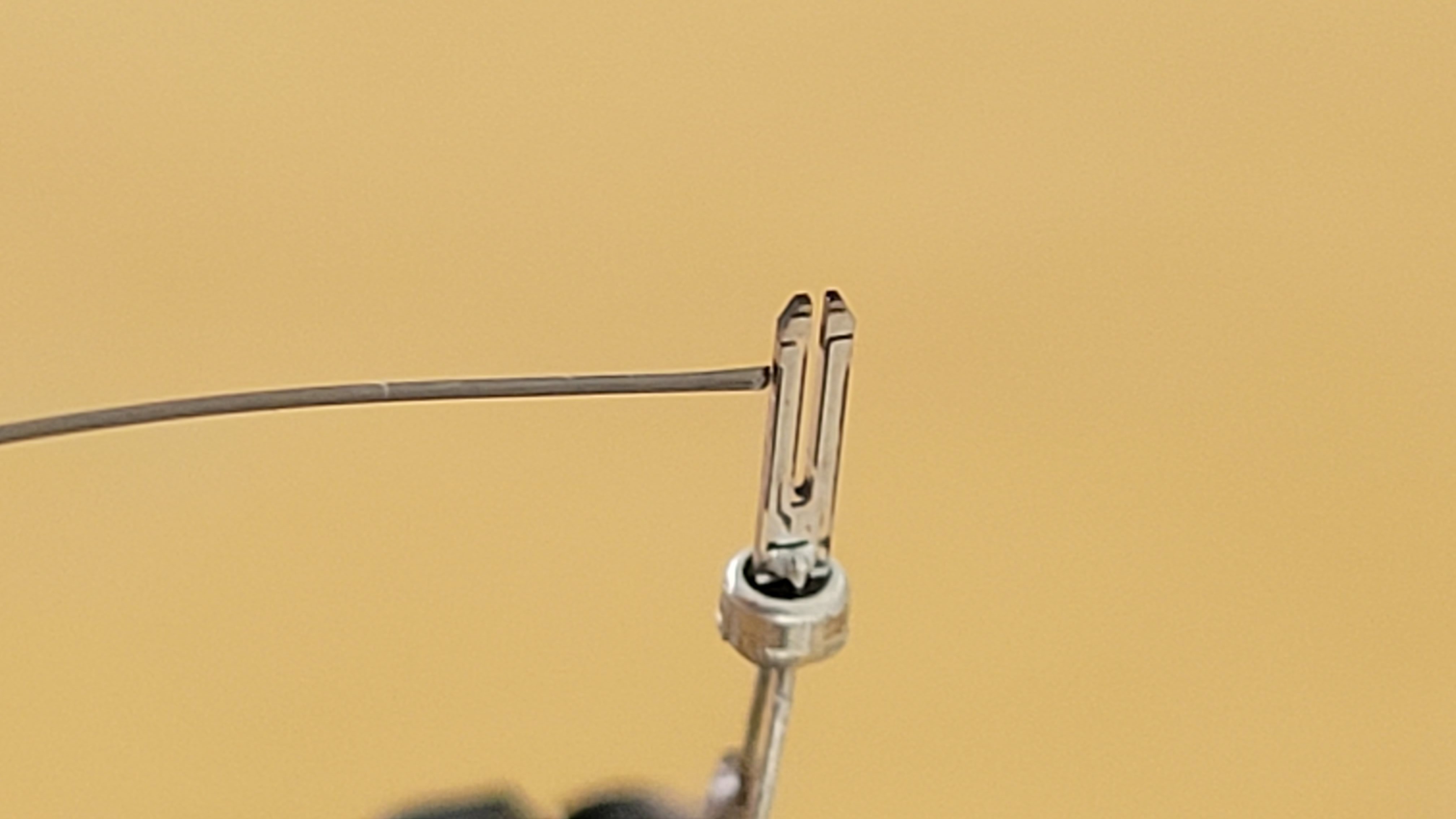
Place it in some unused glass cup, made a anod using copper loop of diameter about 2cm anod (copper wire of 1.3mm).
Attached about inch of Tungsten wire(0.25mm diameter) (cathod) and dipped cathod and anod into the solution.
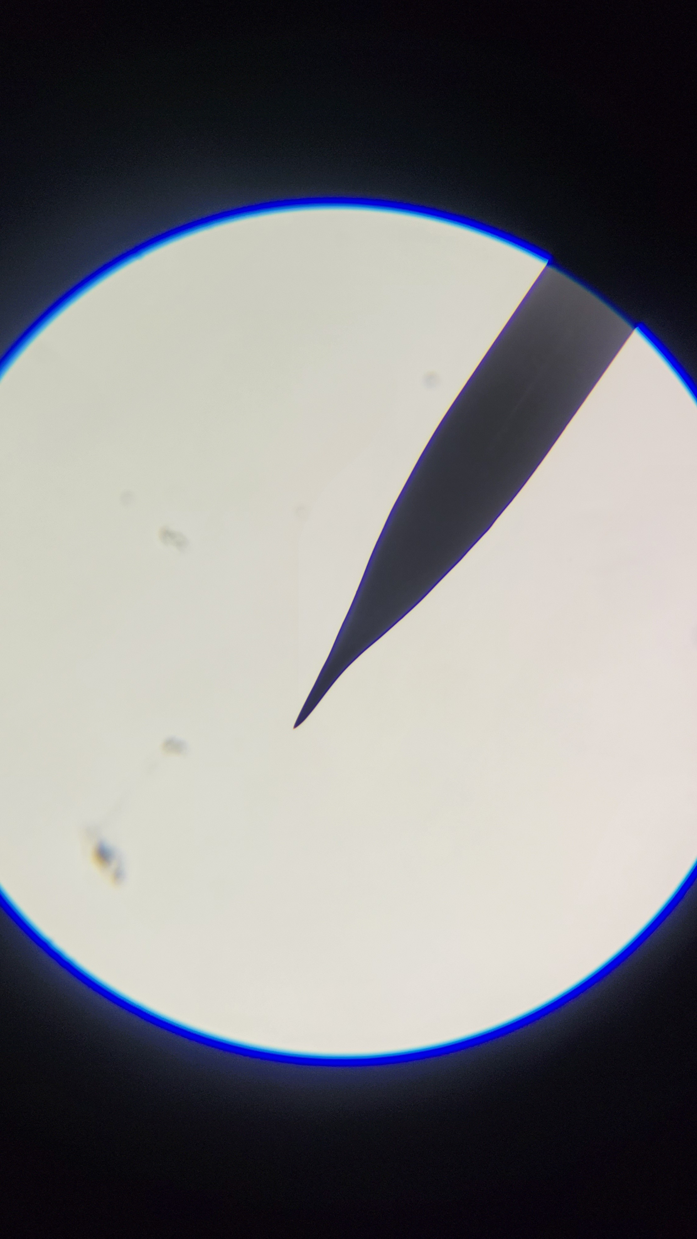
Connect Tungsten wire to plus and copper loop to minus. (If you see a lot of bubbles and 100mA you probably connected wrong polarity) In my case I see a little bit of bubbles only on copper side. After 30 minutes I got some results. (Clumsy me, I managed to drop it when inserting to a microscope, so the tip looks bend)
(Probably there are more steps, we will uncover them as project continues)
XY movement has a very good explanation in Lego2Nano with electric schematic and software algorithms.
For force measure we will use Quartz fork instead of laser one. For two main reasons, first QTF is easy to fabricate at home for a few dollars. Second it eliminate the need for complex laser adjust mechanism and it's electronics.