kelvinA
-
[R] 0.5V solar cell MPPT and expected wattage
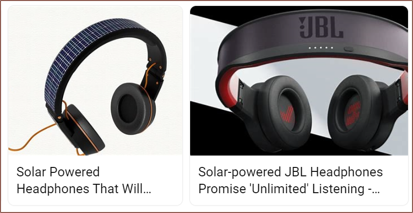
05/25/2024 at 08:21 • 0 commentsSo I was thinking yesterday, considering skipping Tetrescent and going straight to #Tetinerary [gd0151] with a solar powered headband:
However, the benefit of Tetrescent is that one can keep using their preferred headphones (if they either don't have or don't want to wear earbuds / IEMs) and that the displays don't cost £320 total.
Even if that happens, I'd still need to consider the charge circuitry sooner or later, and I got worried when I was reading this energy harvesting log and this was mentioned in the TEG section:
requiring some specialized electronics that can boost <0.5V up to more usable levels
I then did some searching and researching and Bing "deep searching" and the only thing I could find related to MPPT of a single 0.5V cell was this paper that describes a circuit that was implemented on CMOS.
After struggling to absorb the information after a few pages, I noticed that the paper was written in 2014 so surely some IC company should've taped something out by now. Thus I went and searched "mppt ic digikey" and soon found out that there was an "Energy Harvesting" filter. Unfortunately, the chips I could find only supported up to 400mW.
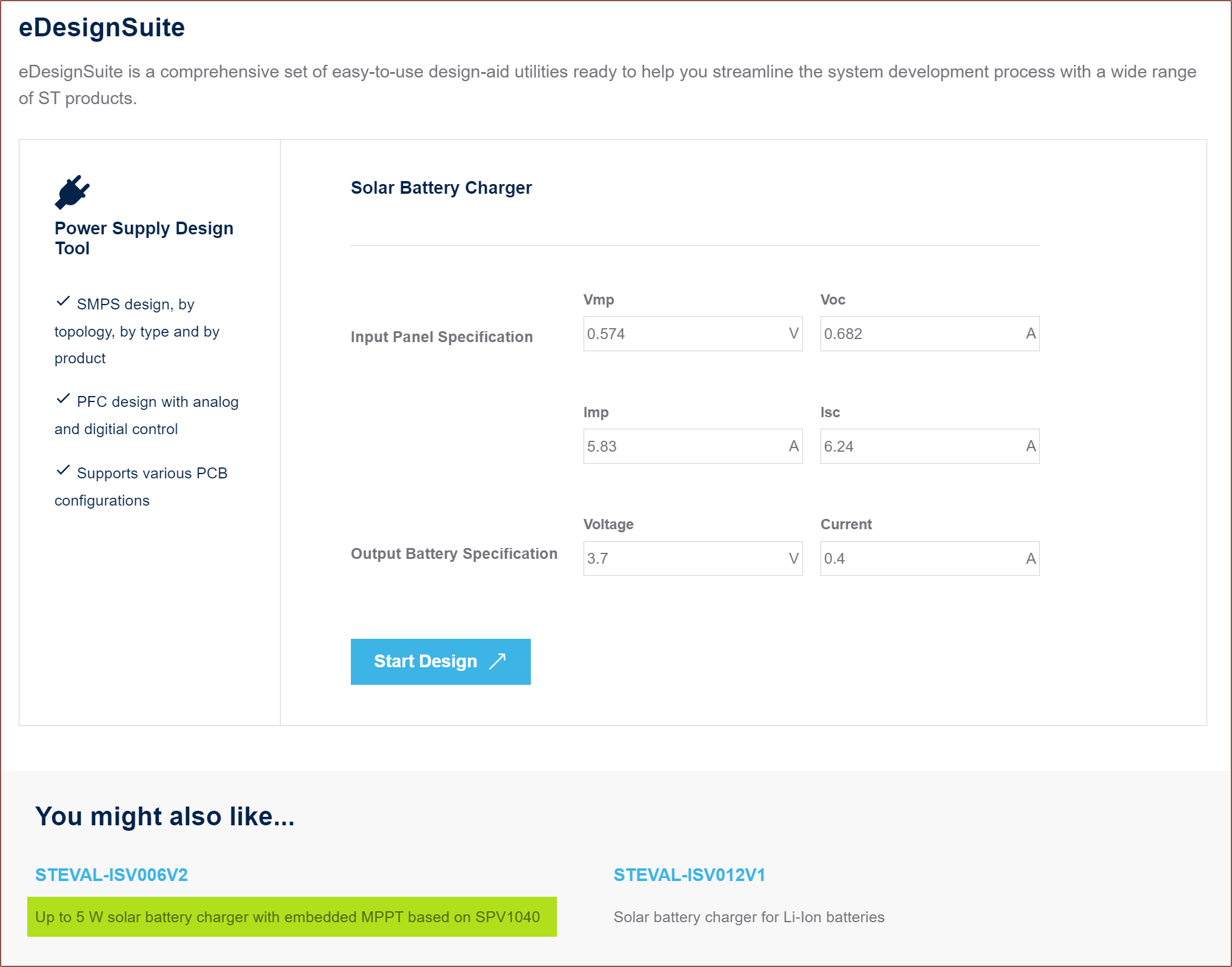
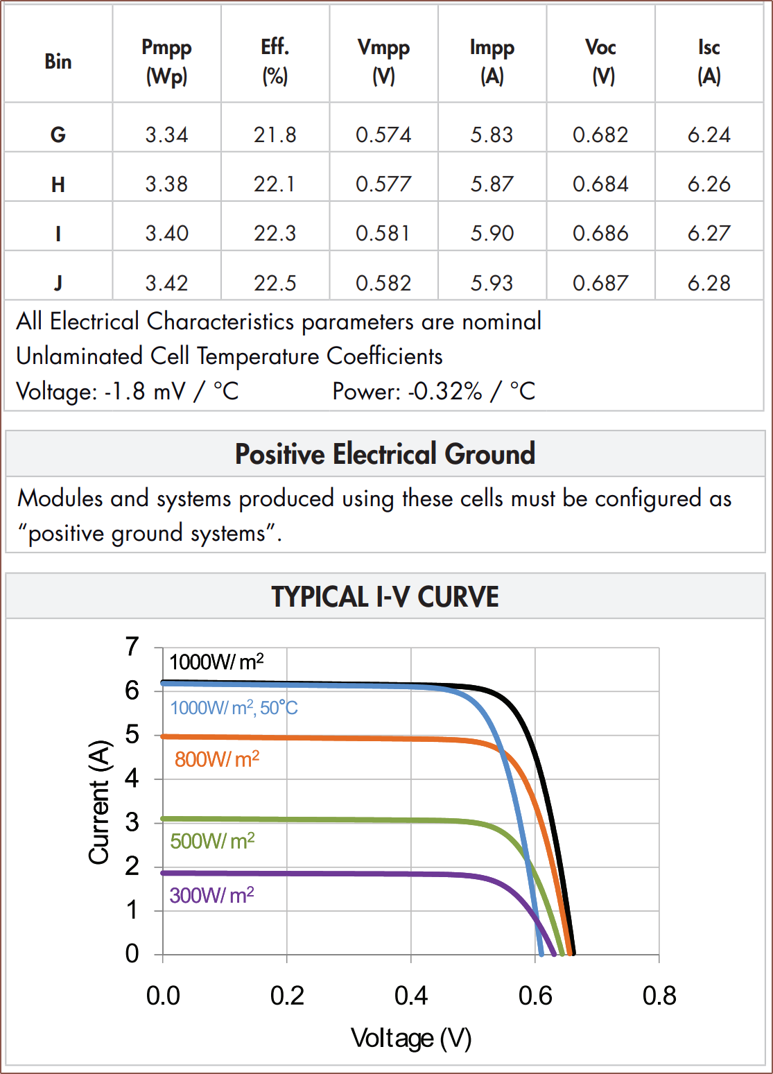
Thus, I searched "solar" in the Digikey searchbox and quickly arrived at the SPV1040, but I couldn't quite find the information I was looking for in the datasheet (which, for some reason, has the Contents page near the end of the entire document). At the bottom of its landing page, there was this "eDesignSuite" thing and I didn't know what all the 3-letter words were but found them inside the C60 solar cell datasheet. The "start design" just brought be to a 404 page, but I went back and saw that there was an evaluation board that could charge up to 5W based on the chip, which was the kind of information I was looking for. The C60 125mm is a 3.34W cell.
The cell on AliExpress is the 21.8% efficiency variant. Looking at the currents, 3.34W is likely the peak 1000W/m2 rating. Looking at these cool animations I found on Solcast, 400W/m2 seems to be a more realistic power profile for most of the UK, seeming to max out under 800W/m2.
![]()
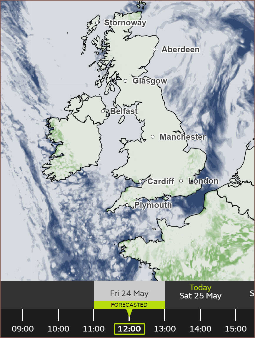
At least where I'm currently at, it's been raining for the previous two days. Seems most of the UK was covered in cloud:
It looks like the expected max solar power would be 4.95A * 0.57 = 2.8W, and that the typical would be 1.4W. Then remember that about 70mm of the 125mm width is covered by the Tetrinsics (not accounting for the thumb Tetrinsic), meaning that the typical power that Tetrescent would obtain outside is perhaps 616mW.
This page states that the controller for the transflective 640 x 480 display found in my recent bundle adjustment might use 20mA, which would correspond to 66mW. The STM32U5G9 uses 2.976mA at 3.3V, 160MHz, which corresponds to 9.8mW. The 5 BT modules present in #Tetoroidiv [gd0152] use the nRF52833 which should use 11mW at 64MHz, but I hope to half this by running the chips at 32MHz. This would add another 27.5mW. Subtracting, there's 511.6mW or so to spare. The battery is 11,111mWh, so there is a good chance that Tetrescent wouldn't need to be charged at all when working outside.
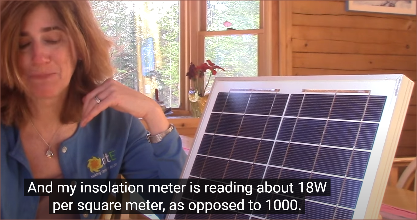
It's more problematic on the inside though, going off numbers in the below video:
Outside was measured at over 900W/m2, so about 5% the power inside. Extrapolating from the 300W/m2 measurement, which is 1.08W at Vpp, an irradiation of 18W would result in 28mW of energy harvested (64mW uncovered).
I looked into the datasheet of the 3.4" MIP display from Azumo and they have typical power consumption of 1.2mW... for updating the display at 1Hz. For 60Hz, it's likely to be at the very same ballpark as the 3.5" transflective. There's very few comparisons with MIP and transflective, with both sides defaulting to comparing against transmissive displays. The power gains would result from being able to adaptively update the refresh rate and use a slightly lower power mode on the U5G9 that still has a 7MHz SPI bus enabled.
-
[A] Details page before 13 Jan 2024
01/13/2024 at 08:19 • 0 commentsNotable Tetent projects, sorted by project log count:
- Input element: #Tetrinsic [gd0041]
- For Teti: #Tetent [gd0090]
- Wearable: #Tetent TimerSpy [gd0136]
- x86 PC Handheld: #Tetent UMPC [gd0149]
- Desktop: #Tetent TestCut [gd0139]
- Solar Powered: #Tetrescent [gd0150]
Input Device Project Goals
- Hardware
- Charged by (sun)light and useable outside
- Able to
- enter text at or above 240wpm without dictation / dictionaries / shorthand / abbreviations
- move a cursor with the same or better accuracy and precision as a mouse / trackball / trackpad
- be played as an instrument and output MIDI data
- manipulate a 3D viewer with the same or better control as a 3dconnexion Spacemouse
- receive haptic events from Trackmania and send them to my fingers
- Compatible with fingernails less than or equal to 5mm long
- Ambidextrous
- Usable with 1 or 2 hands without layout changes
- Wireless connectivity
- Self sanitising
- Software
- Configuration
- Set layout on device
- Mouse acceleration and momentum curves
- Applications
- Word processor / note taker of some kind, which also accepts mathematical equations
- Something like JAM with Chrome, but also has strings / brass / winds
- Configuration
-
[T] Braille, Svalboard, mode-hopping and height variations
09/16/2023 at 15:50 • 0 commentsBraille
Partially because of #Electromechanical Refreshable Braille Cell but also #Sotto: A Silent One-Handed Modular Keyset and #Neotype: Haptic Computing, I've been wondering what could be done about being able to read the content I enter without requiring to use my eyes.
I'm considering a vertically-read, braille inspired solution, whereby each row -- which can have no dots, a left dot, a right dot or both dots printed -- has it's own specific haptic feedback through 3 of the Tetrinsics. One of the concerns I have is reading speed.
Along with sliding the fingers up/down, it could be possible to instead rest the fingers on the Tetrinsics and they actually move up and give one haptic event per magnet bubble:
Thus, the haptic sensation for a standard 6 cell would be
- Tetrinsic starts moving
- Gap between magnets
- Haptic event (or nothing if there's 0 dots on the row)
- Steps 2 and 3 another 2 times
- Tetrinsic slows down (and stops if at the end of the character stream) to mark the end of the character
Now, I can only imagine this would only be useful for when I want to type and watch the world go by on a park bench (or not look down at the screen), as I can only assume the human mind has one processor for this kind of data. Maybe it'll allow writers to look up at the sky and imagine their worlds instead of looking at a stream of characters?
Svalboard inspired layout
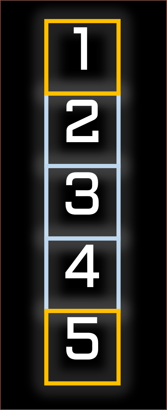
I've also been looking for clues inside the Svalboard / Lalboard / Datahand Discord and this KBD article, and am considering a 5 key per tetrinsic solution. This is comprised of 3 zones that the user presses down and two end-caps that act like the magnetic side-keys on Svalboard.
Mode switching / hoppingI'm starting to notice that there's a lot of states in this finite state machine I'm making here.
- Character entry (parallel entry / taipo / svalboard)
- Number entry (for parallel entry / svalboard as Taipo already handles this)
- Equation / Greek symbol entry
- Function / macro entry
- Mouse entry
- 3D mouse entry
- 6D (3D + 3D) spacemouse entry
- Game controller entry
- Pen / stylus entry
- MIDI entry (which further has various instruments / synthesiser interfaces such as a guitar instrument actually feeling a bit like strumming the strings)
- Some kind of haptic reading output mode
- Run application on Tetrescent
There's about as many modes as on my Casio Classwhiz calculator, and I need to consider a way of being able to hop between them with minimal time and mental-compute overhead.
Height variations
For ergonomic comfort, I'm considering dropping down the outer vertical Tetrinsics:
-
[P] Concept prints and print settings
09/14/2023 at 22:38 • 0 comments[9 Sep 2023]
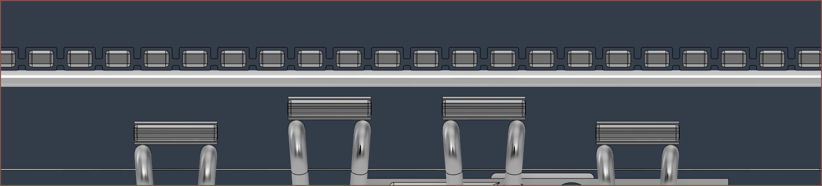
The actual changes that I've implements aren't that numerous -- I plan to use a 2.0" transflective LCD positioned closer to the north edge, the Thumb Tetrinsic has been moved north to be the same disance from the edge as the left/rightmost Finger Tetrinsics and the height of Tetrescent is down from 44mm to 40mm -- but I've learned some things about my printer settings when trying to print out the printable concept.
Transflective LCD
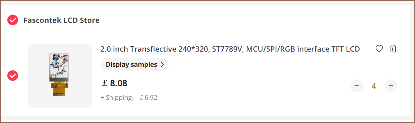
I was able to find the KD020QVRMA002, a 2.0" 240x320px transflective LCD:
I can't find any concrete numbers, but believe it would be less reflective than the 2.7" reflective LCD. There's also 80 less vertical pixels, but I do get multiple colours and a backlight for low-light use. It also allows Tetrescent to be thinner, assuming that there's nothing else contributing to the overall thickness.
It seems that transflective LCDs come in more sizes and at lower costs than rLCDs, especially ones with frontligting.
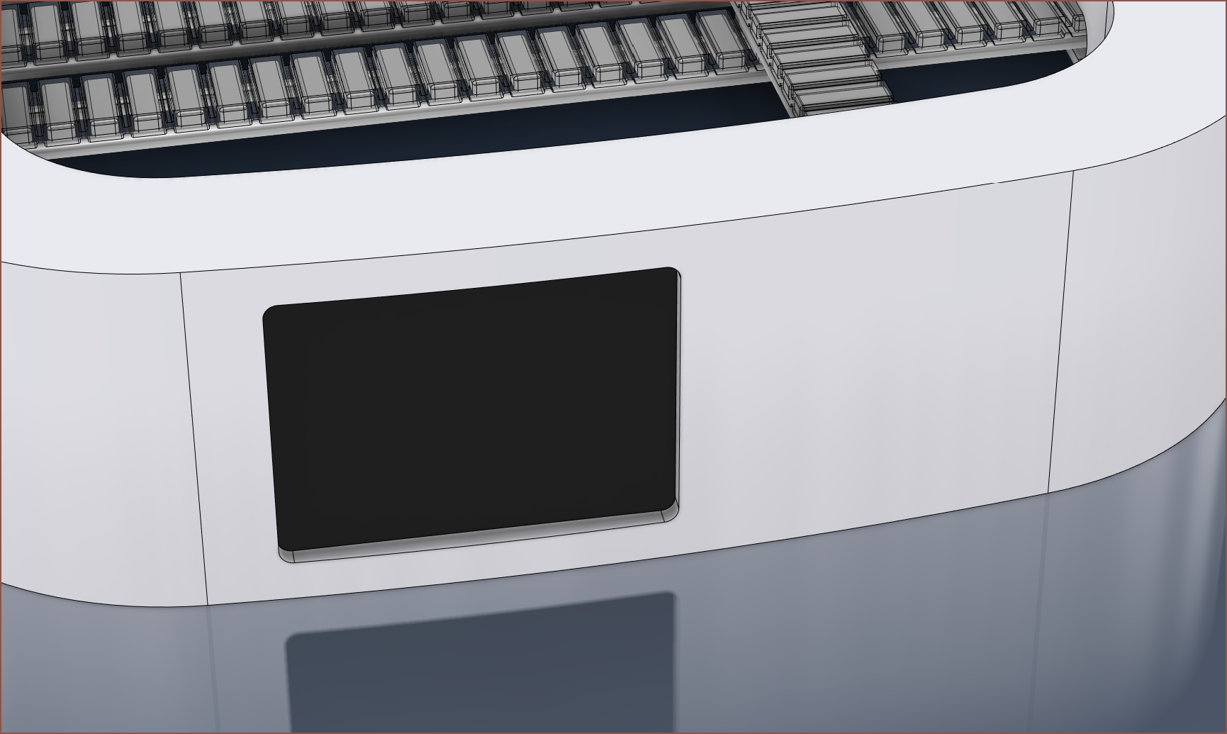
It's been placed like so to allow space for the Thumb Tetrinsic as well as it being a slightly less steep angle to see by a user. My only concern is that the square 240x240px area I plan to dedicate for the word processing interface is probably going to be the size of a 1.54" smartwatch (which I have typed on with the use of a folding keyboard just fine). It likely just means only a few words would be visible at any one time. The bottom 240x120px is dedicated to the UI concept I made for Tetent Concept3.
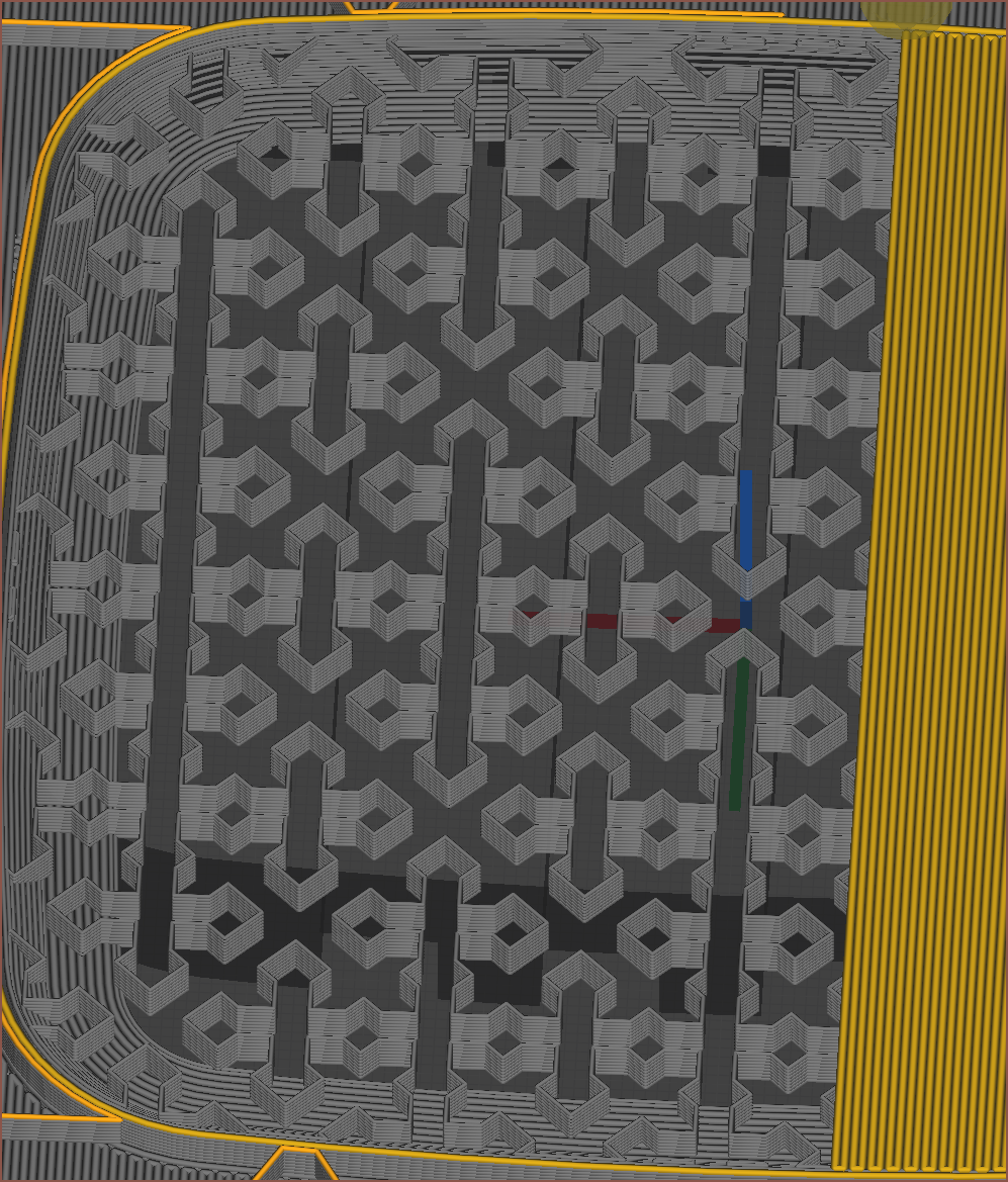
Printing the concept
The first attemt failed somewhat mysteriously, but I think it had something to do with some peeling-up top layers. My roughly-tuned supports were removeable, but they didn't break off as easily as I'd like, nor provide a nice looking under-layer.
For the peeling top layers, I had enabled Skin Edge Support, but I don't think the 6 layers was enough for it to stabilise. Instead of a fixed layer count, I opted to set "Skin Edge Support Thickness" to 10mm.
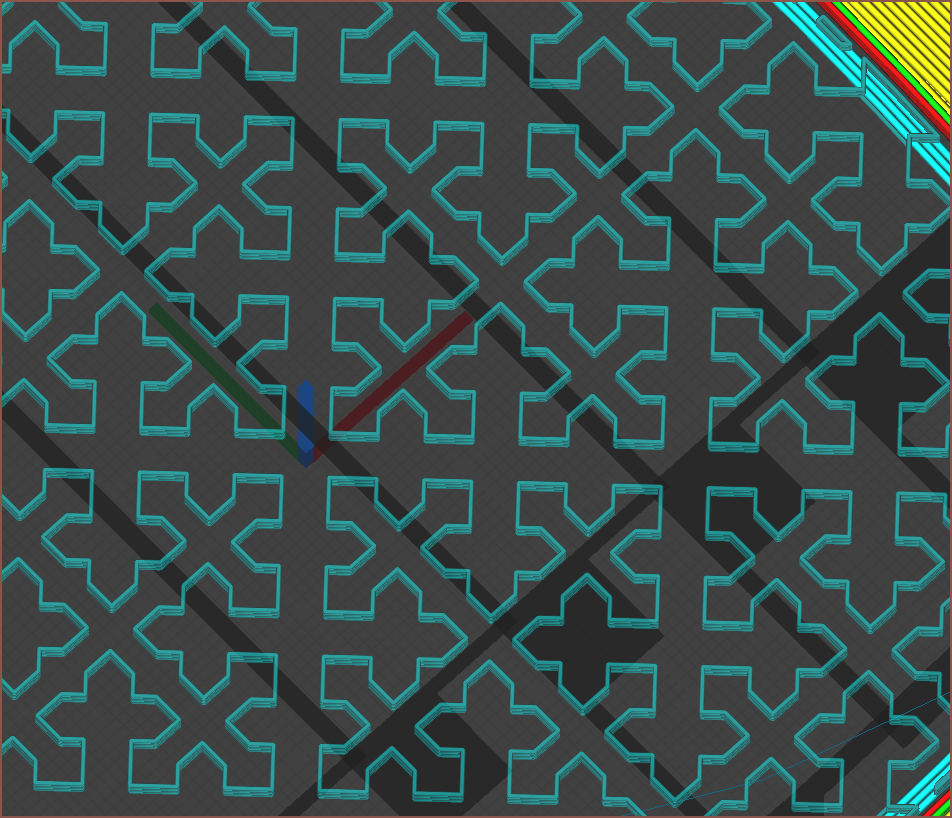
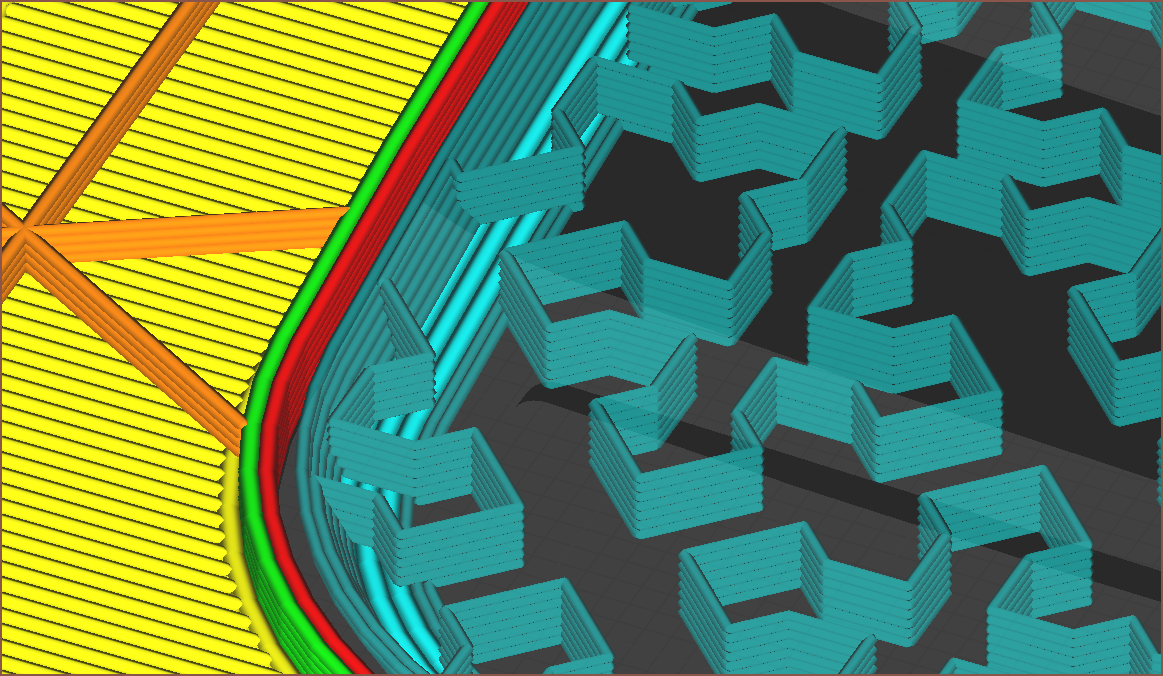
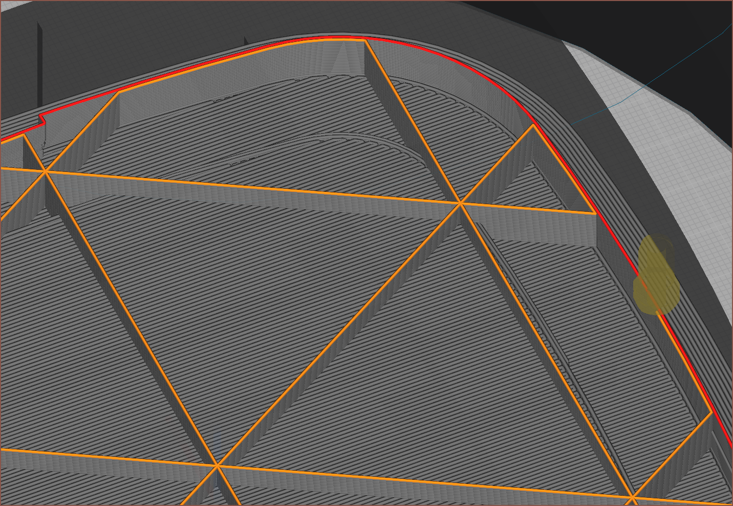
Tackling the supports, I did some researching and changed my support line width to 3/4ths of the nozzle diameter. Then I looked into support pattens and liked the look of "Cross":
It looked like it would be a springy support structure that would break off easier. The only issue was that there seemed to be some small extrusions on the right edges, so I added a single wall via "Support Wall Line Count":
I also found out about "Enable Conical Support", which slopes the edges. This is good, since it means that the support isn't right next to the inner walls all around.
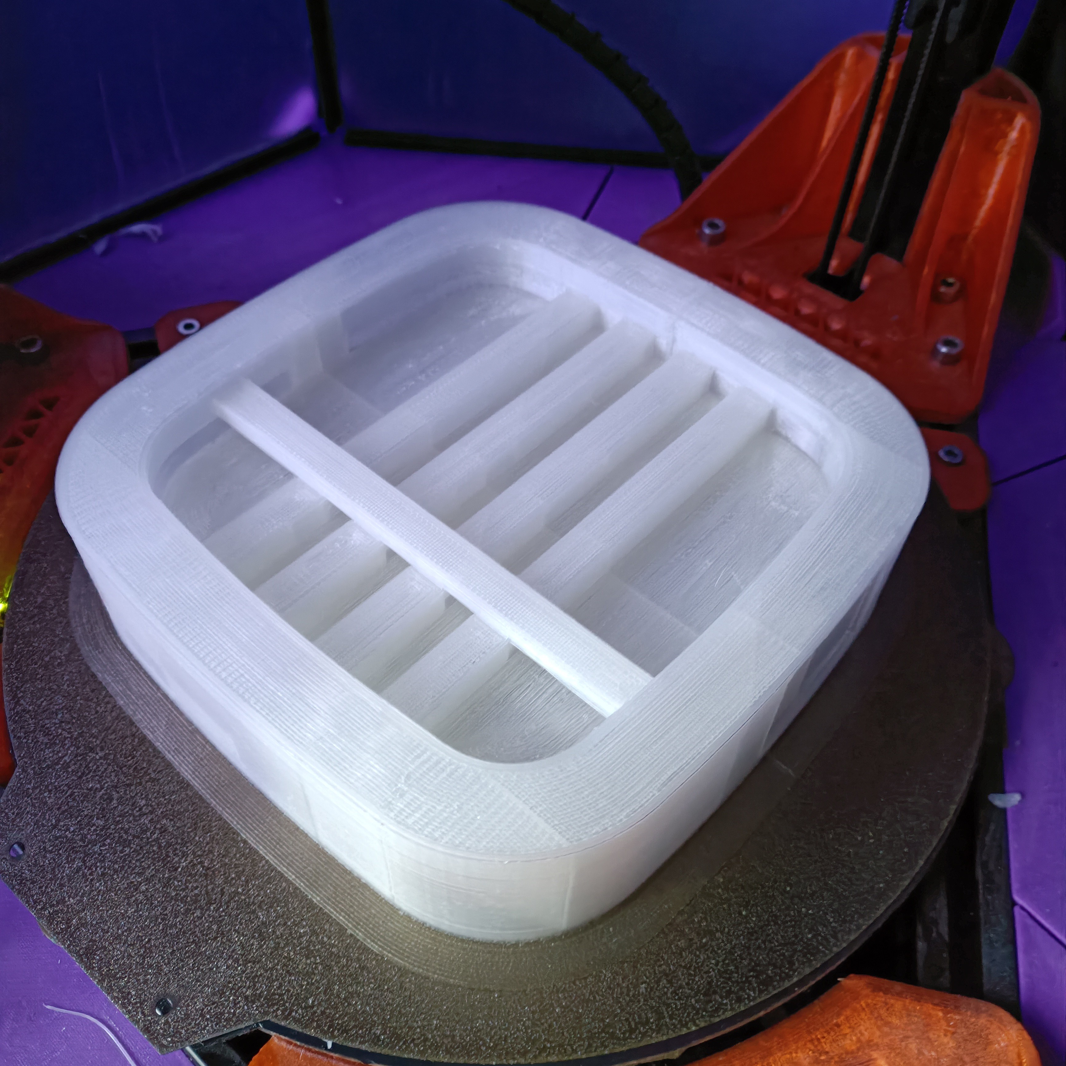
The subsequent print actually succeeded this time, and it does seem that the increased skin edge support helped. This is what it looked like when it was printing:
I also saw that the print was peeling away from the brim, so in the next print I reduced the bed temperature from 60 to 54 degrees celcius and that seems to have fixed it. Trying the concept
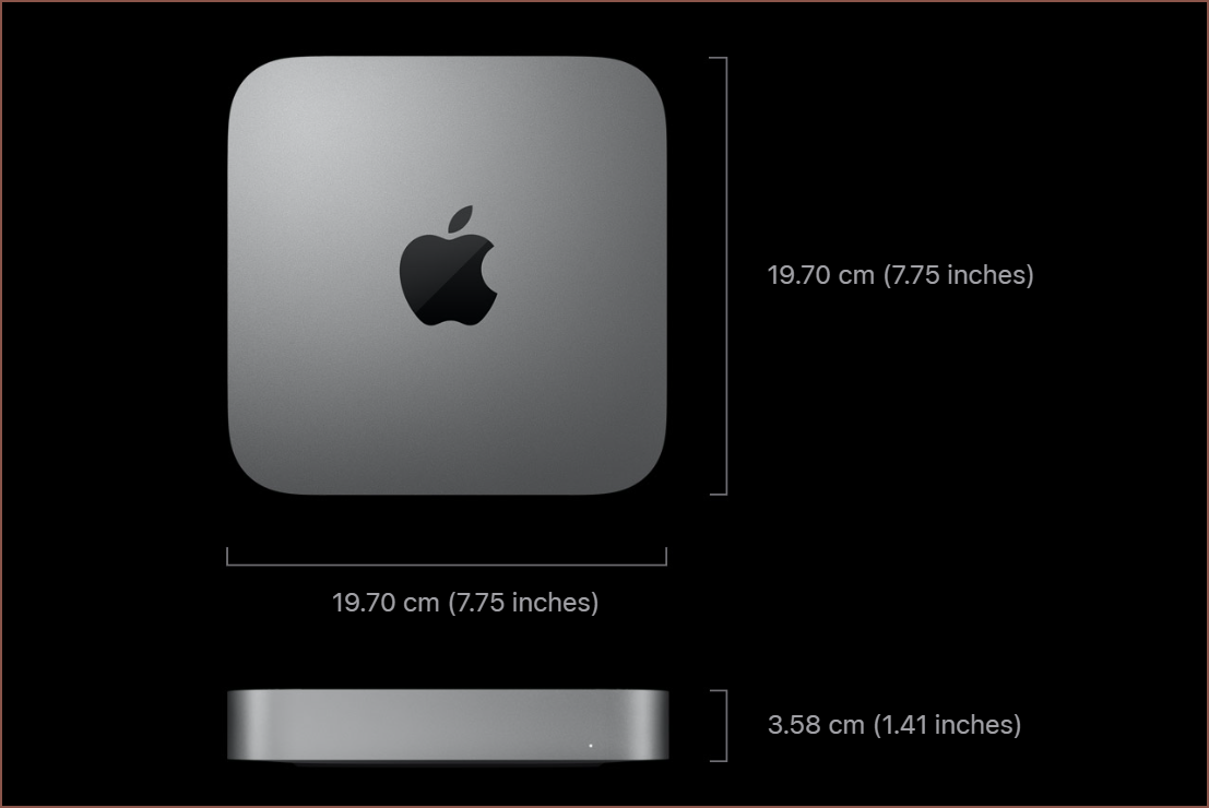
The first thing I noticed was that it's quite large in comparison to my keyboard / mouse. I can still hold it on one hand fine though, but it's more the size of a mini-pc. It's smaller in XY than a Mac Mini though.
So I sat on some stairs and I also tried it outside to see how it fares, since desks don't grow outside. Suprisingly, I think I can get it to work by getting my palm to push Tetrescent into my lap, holding it in place. When outside, sitting on railings or the floor, I was eating a sandwich in my other hand to get some real-world, single hand experience.
The only thing I thought needed changing was that the thumb was too close to the south edge. Thus, I've moved the Thumb Tetrinsic northwards:
Printing the next concept attempt
I wanted to reduce the amount of material needed to print the next concept, as well as increase print reliability. I changed my top/bottom pattern from "Lines" to "Zigzag" and reduced its speed from 60 to 54mm/s and reduced acceleration to 300mm/s/s. To counter this speed decrease, I increased my bridge speed from 30 to 45mm/s and reduced the "Bridge Skin Density" to 90%.
I was expecting to see gaps, but I guess that's not the case when the skin flow is 110%. I also wanted to go down from 2 to 1 outer shell wall, but past experience (quite a few years ago now) suggested that wasn't a reliable idea. I thought I'd go with a "1.5" thickness by enabling "Connect Infil Polygons":
This also means that the skin support is made up of 2 or 3 lines instead of just one. I predicted that this would allow these lines to stabilise faster and reduced the thickness to 8mm.
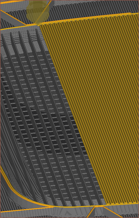
So I sent that to print and the first thing was that the first layer was changing direction too fast and causing the supports to peel up in a few places, so I also reduced the initial layer acceleration to 300mm/s/s.
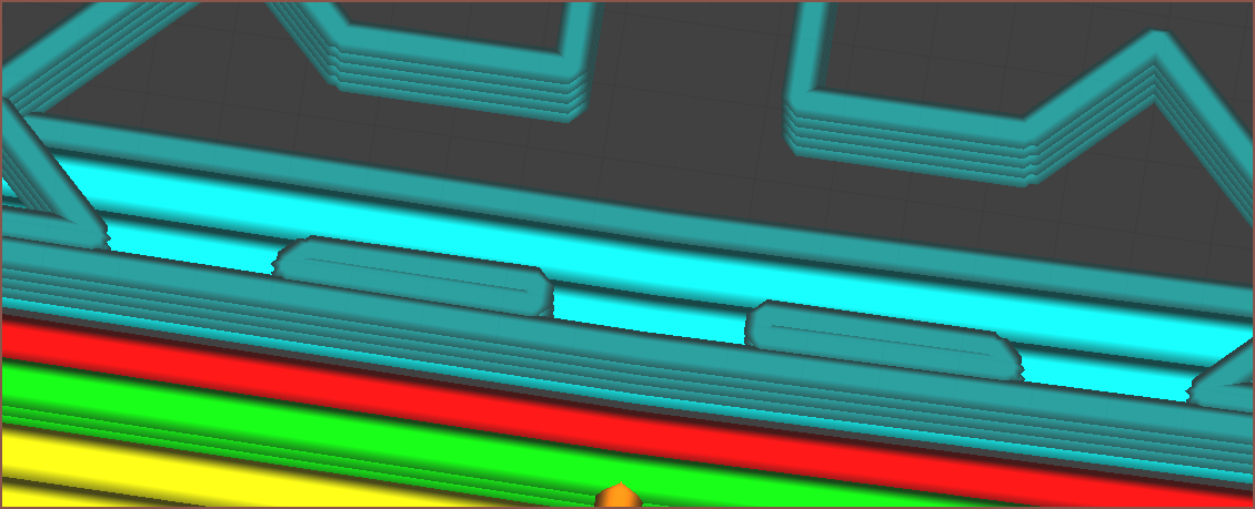
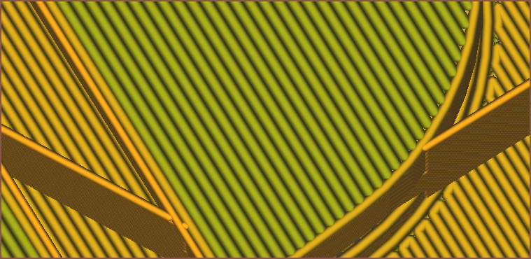
I noticed that this bottom layer that is just about the supports laid down much better than the first time. The only issues were those long gaps that are in the same direction as the layer lines. At least now I know why my first supports were so bad using ZigZag:
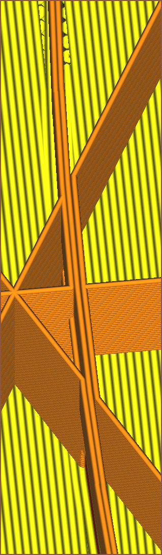
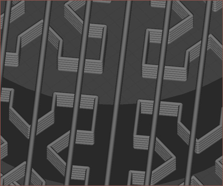
Unfortunately, "Support Infil Line Directions" only works on patterns such as Zig Zag, and had no effect on the Cross pattern. It's possible that I can use a support interface roof and set "Support Interface Line Directions" to "[45]" to produce the below pattern, however something like 23 (I can't use 22.5) would need to be used since there are still long gaps in the Cross pattern for 45 degree angles:
The sag isn't that bad, and this print is probably going to be one of the largest areas that even need support, so I think I'll be fine with the Cross pattern at 15% fill.
I did notice that the skin didn't really attach to the perimiter, so I've increased "Skin Overlap Percentage" from the default 5% to 10% (the same as the default "Infill Overlap Percentage".
Trying the second attempt
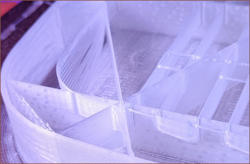
So the print finished as I was writing this log.
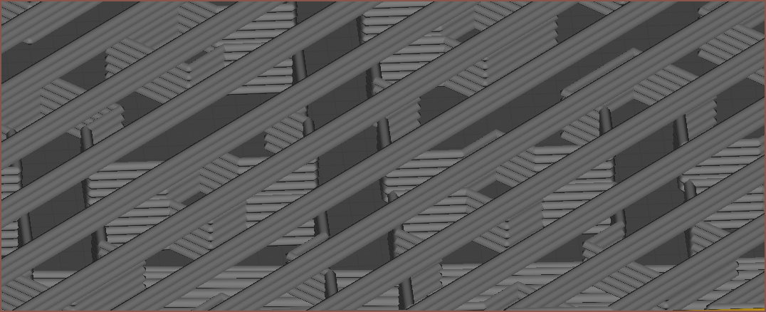
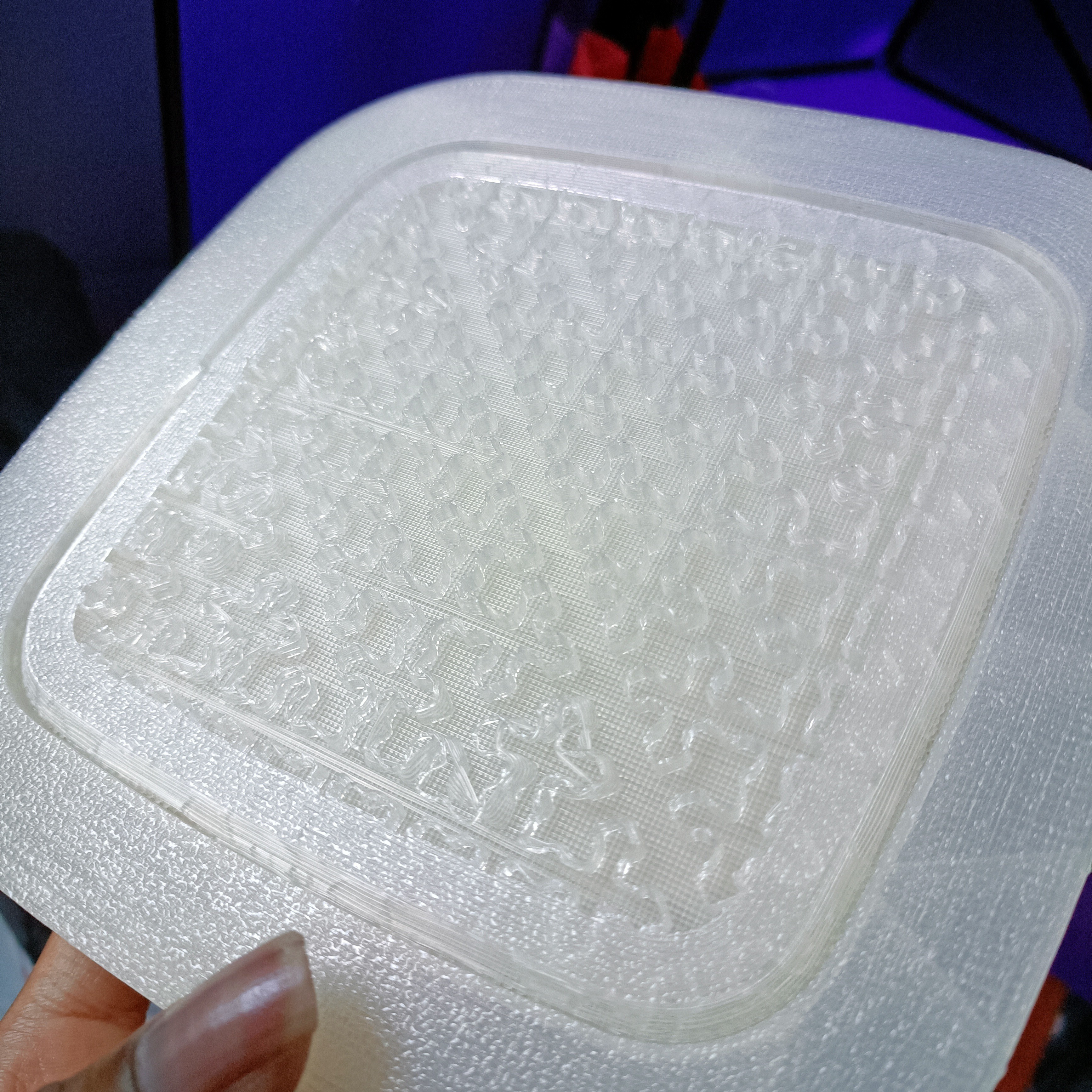
It certainly stuck better and has less warping, so I'll continue to use a bed temperature of 54C going forward. The support also looks good:
Unfortunately, the support has become harder to remove. The long, unsupported sections also sag and detach from the rest of the otherwise good looking underside. I might try 45 degree zig-zag with no outer wall next time.
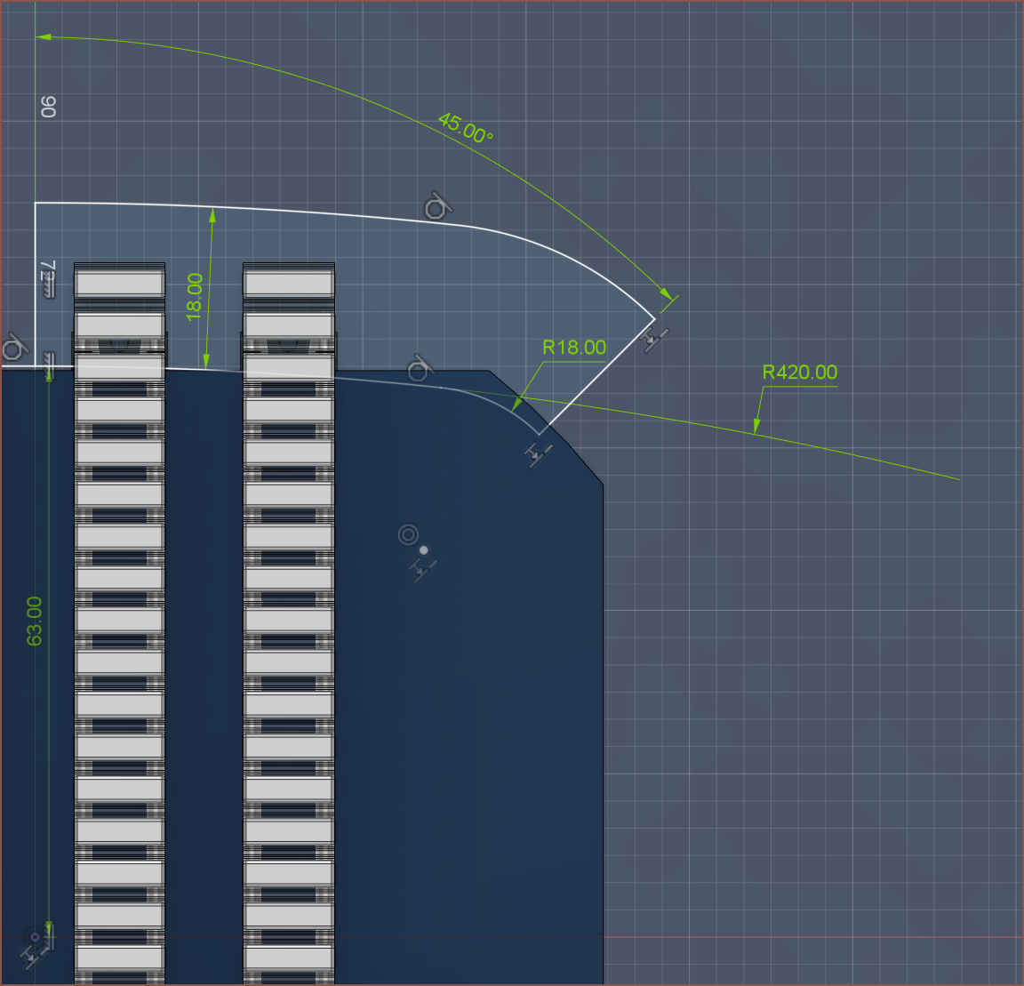
The actual feel of the layout feels fine, although my thumb is still hitting on the corner. Reducing the radius also makes the device look sharper-edged. I've only been able to reduce from 20mm to 18mm, as even 15mm looks kind-of sharp.
The solution is probably to increase the inner radius from 63mm to 64 or 65mm.
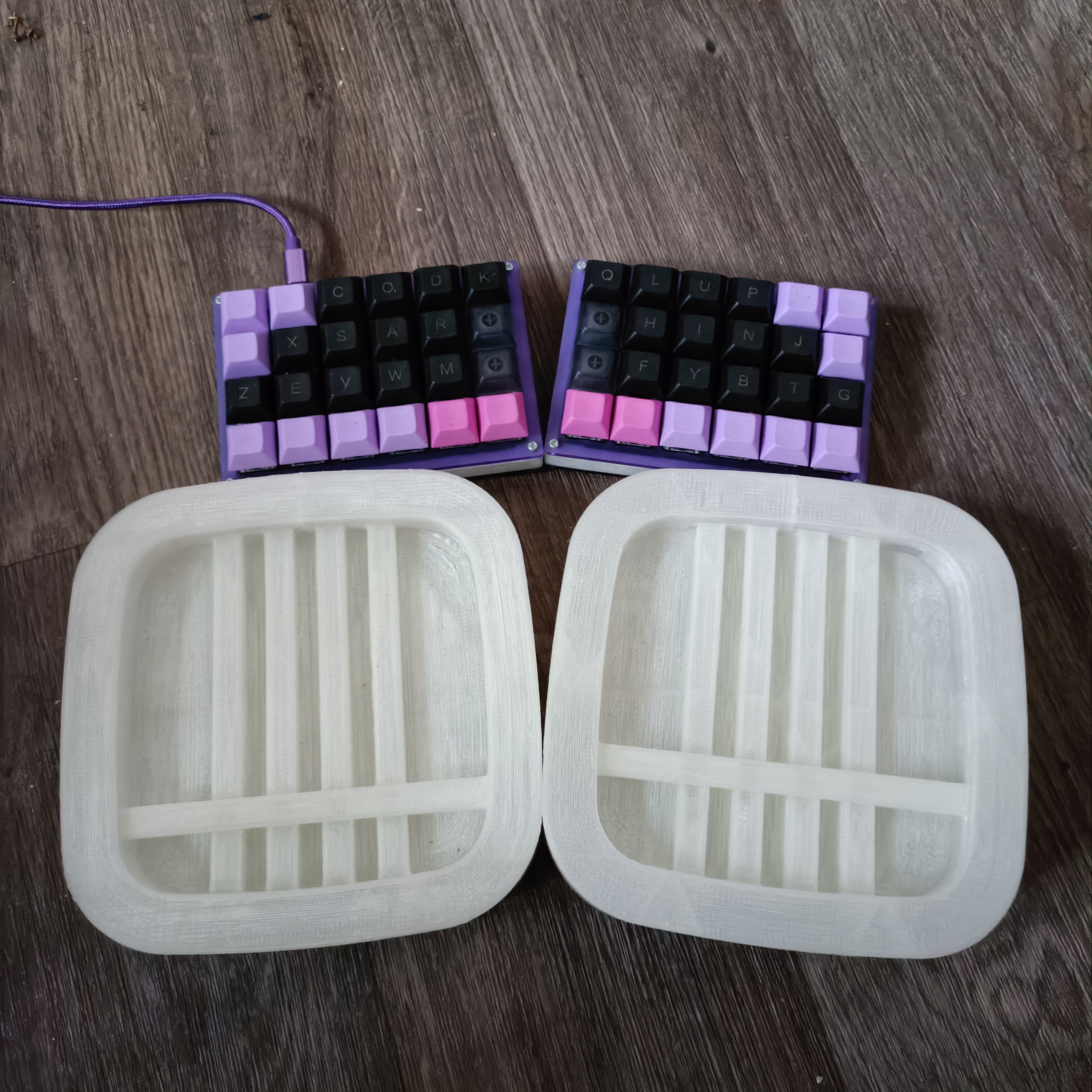
Here's a size comparison with my "Let's Split" keyboard:
Airberries on top, first concept print on the left and second print on the right. -
[R][M] Low power screen, word processors and device shape
09/14/2023 at 22:37 • 0 comments[18:30, 6 Sep 2023]
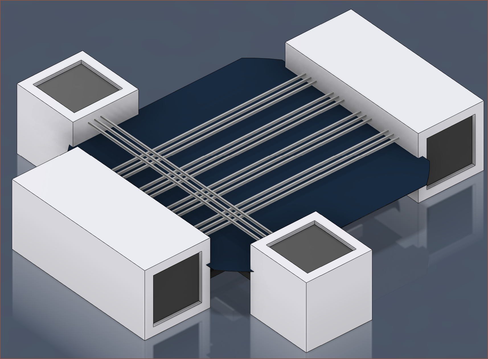
As you may have noticed from the renders, there hasn't been a screen like there should be. This is mainly because I was going to model the basic idea and then see where a screen could be.
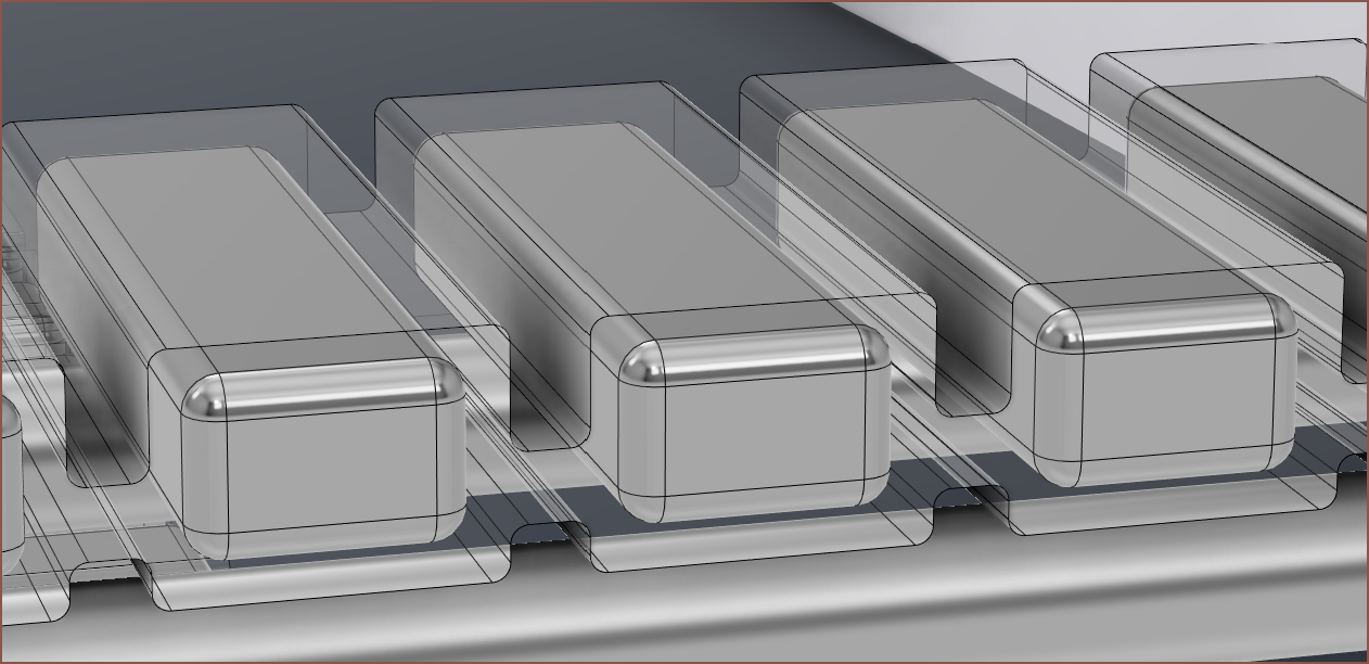
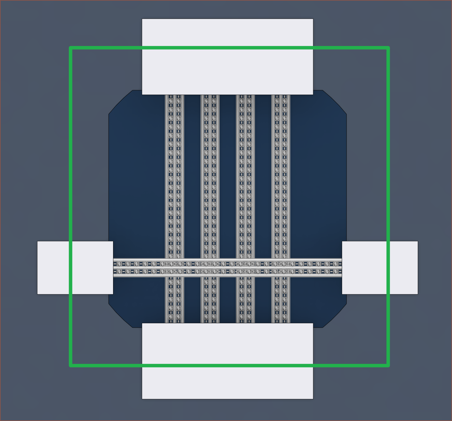
Due to the loss of the 580KV BLDC motor, a new Tetrinsic Concept has been proposed which, among other things, aims to reduce the size of Tetrescent's footprint while retaining the 125mm solar cell. In practice, that means reducing the size of the white parts so that they fit in a smaller green square:
A few days ago, I was putting together the BOM of both Tetrinsic and Tetrescent together, and I put in the price for the 4x LPM013M126 transflective LCDs that I was planning to use since the latest Tetent TimerSpy concept. Now this came to £50, prompting me to reassess if I actually need a screen at all. Due to the amounts of features and the desire to have everything set up on the device (meaning that settings are stored between PCs and I don't have to initially code programs for each of the main operating systems), it's in my best interest to keep the screen. I also considered cheaping out with some LCD panels, but if I gave / demonstrated this device to someone, it would easily be seen as a design flaw to have a solar panel absorb 3 watts for a screen to emit 30+% of that power back out and compete (and likely still lose) to the sun.
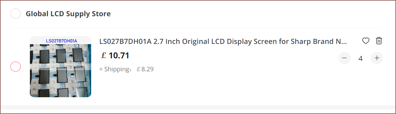
However, it's likely that Tetrescent would be used at a distance further away from the users eyes than the previous Tetent concepts. A 2.7" rLCD would be a more useful amount of space, and it means that I'd be able to display more information for only about £2 more per panel.
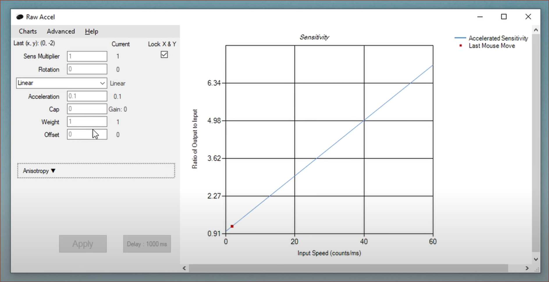
What would I even need to display? As I mentioned earlier, settings is one of them. Yes there's obvious stuff like key layout, but there are also things that I didn't consider until I did some research, such as mouse cursor acceleration curves that I found out watching this video about using a trackball for FPS games.
The next is a planning app called #TaskPercent [gd0140] and another is a word processor. I only just found this out now, but there are a few dedicated devices for just writing text. I essentially had the same setup with a used SHARP HC-4100 PDA that mainly ran Word for Windows CE. I looked into reviews and comments about the Freewrite Traveller and its cheaper alternative, a line of AlphaSmart devices. The former uses an e-paper display can save documents on the cloud, wheras the latter uses a character LCD that plugs into a PC to retype the document. The r/writerDeck subreddit is a good location for information.
- Benefits mentioned for the Freewrite Traveller
- It's a specific device to just type, without notifications
- It's not easy to look back at one's work, thus they become more focused on typing and less on editing
- You can type outside
- Lasts very long on a charge
- Drawbacks mentioned
- It's $500
- Not always charged if not used for a while
- Tetrescent has a solar panel, so as long as it's not stored in a cupboard, it should be able to stay topped up.
- E-paper has noticable and somewhat distracting latency
- The framerate and latency just won't be fast enough for Tetrescent at all, and one of the reasons behind using MIP / rLCD. This is also the reason why character LCD's cannot be used either, since the pixel transition time is too long.
- The display is kind of small
- I'm hoping that Tetrescent can be placed closer to the users eyes, but that likely would also require a stand. The good news is that, unlike a keyboard, Tetrescent should still be ergonomic when on a stand closer to eye level.
- It wasn't used enough
- Hopefully, the (hypothetical) speed advantage over using Tetrescent over a keyboard in day-to-day computer work, as well as its various additional modes for sketching and gaming, result in its continued use.
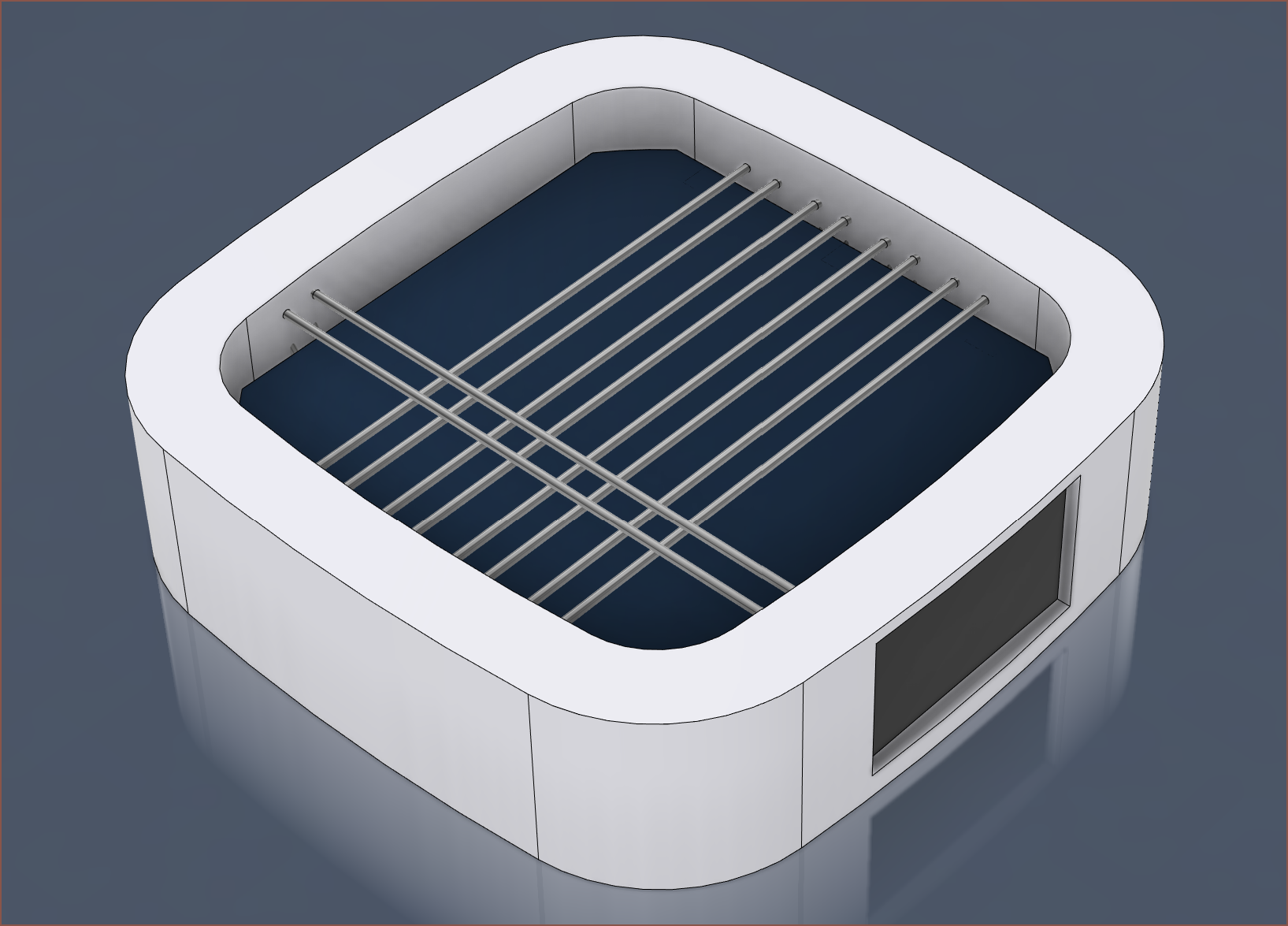
For the shape of the new Tetrescent concept, it's likely going to be a filleted chamfered square, similar to #Teti [gd0022]:
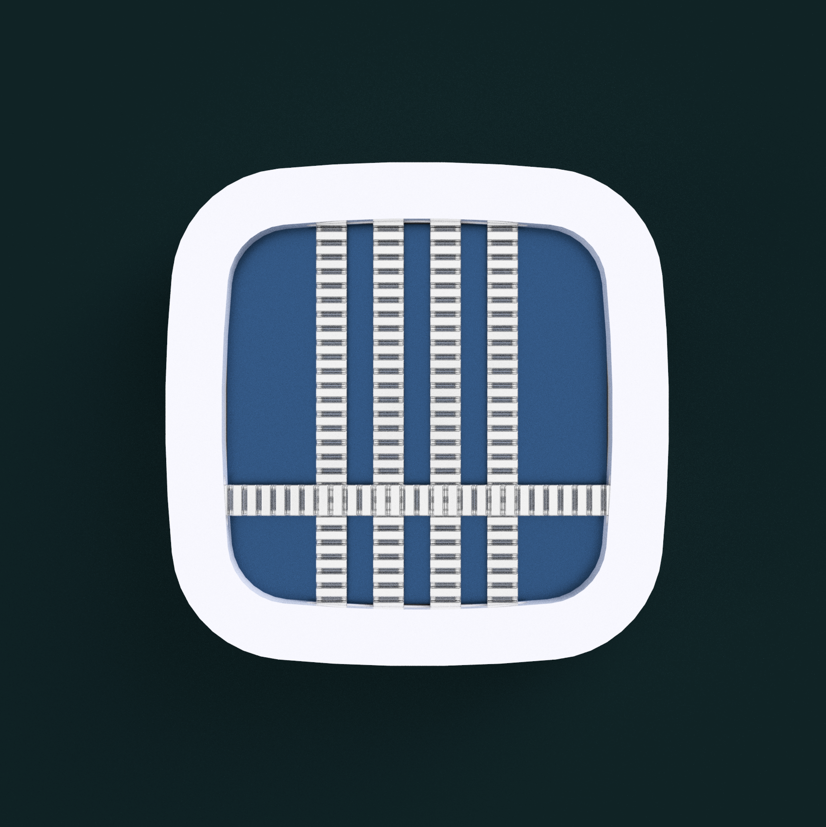
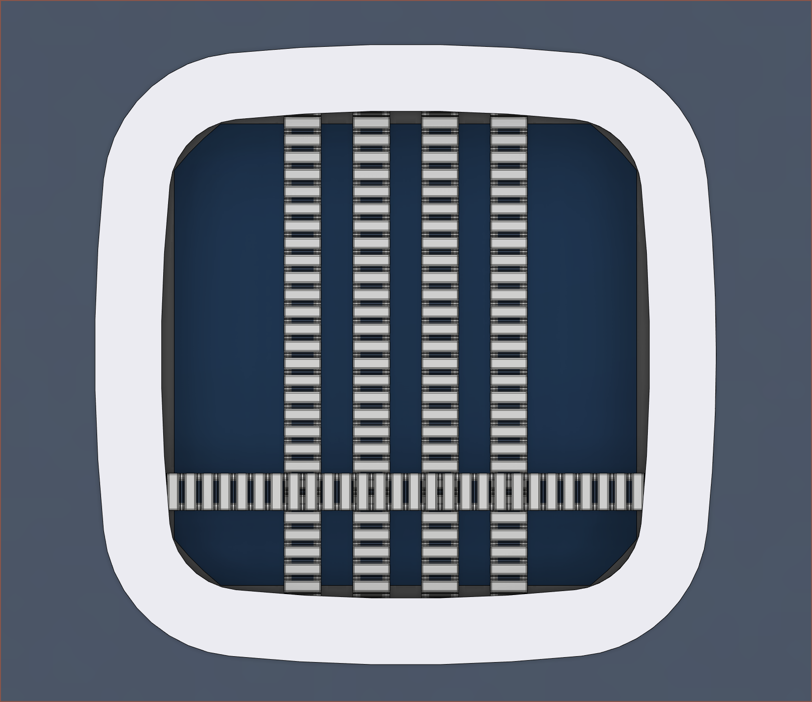
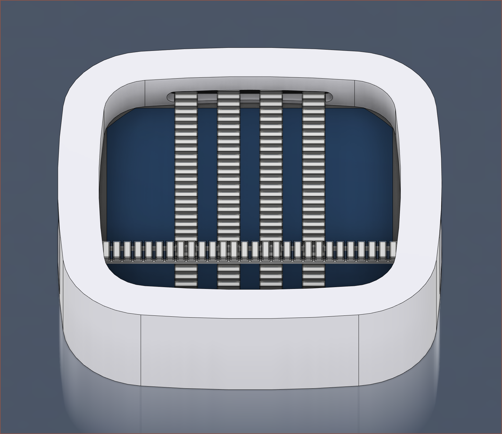
However, I recently saw a Zune Wikipedia article and noticed it's "squircle" input pad:
Thus, I was thinking that a squircle design could look more fluid and timeless:
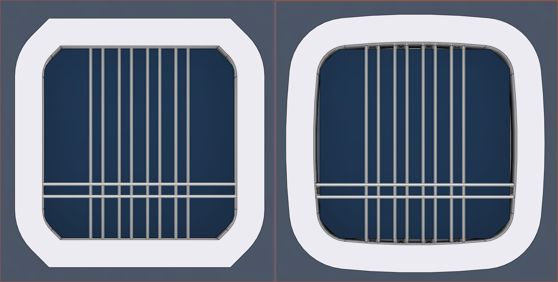
Here's the 2 shapes side by side:
I can't discount how much more refined and mellow the squircle one looks. This is to be expected, since Apple's user interface guidlines for the Vision Pro suggest to use rounded shapes instead of ones with corners so that the eye focuses on the center instead of the edges. I also can't help but see it as one massive, navy blue blackberry trackpad.
I'm just concerned that it lacks that "personal touch". I'm going to sound like a Prusa Research T-shirt when I say this, but any designer on YankoDesign would likely design with a squircle, but I'm the small handful that would use a filleted chamfer.
I will admit though that if I entered both designs into a competition or asked a poll, the squircle would probably win.
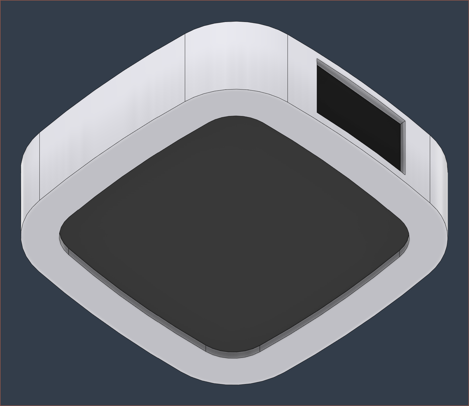
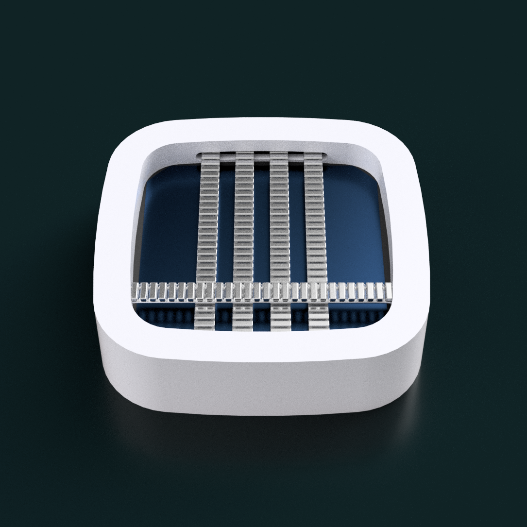
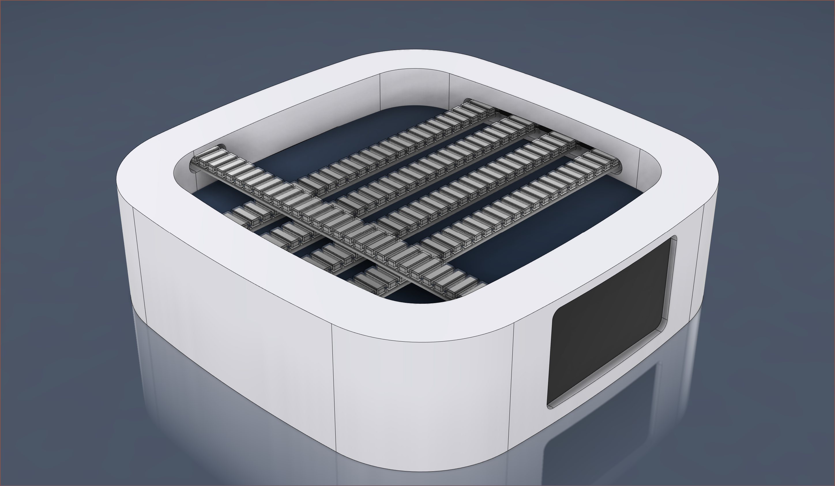
[21:00] I've continued to model the squircle design to make it a bit more detailed.
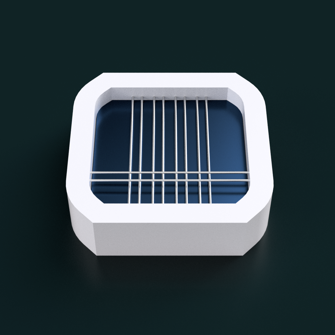
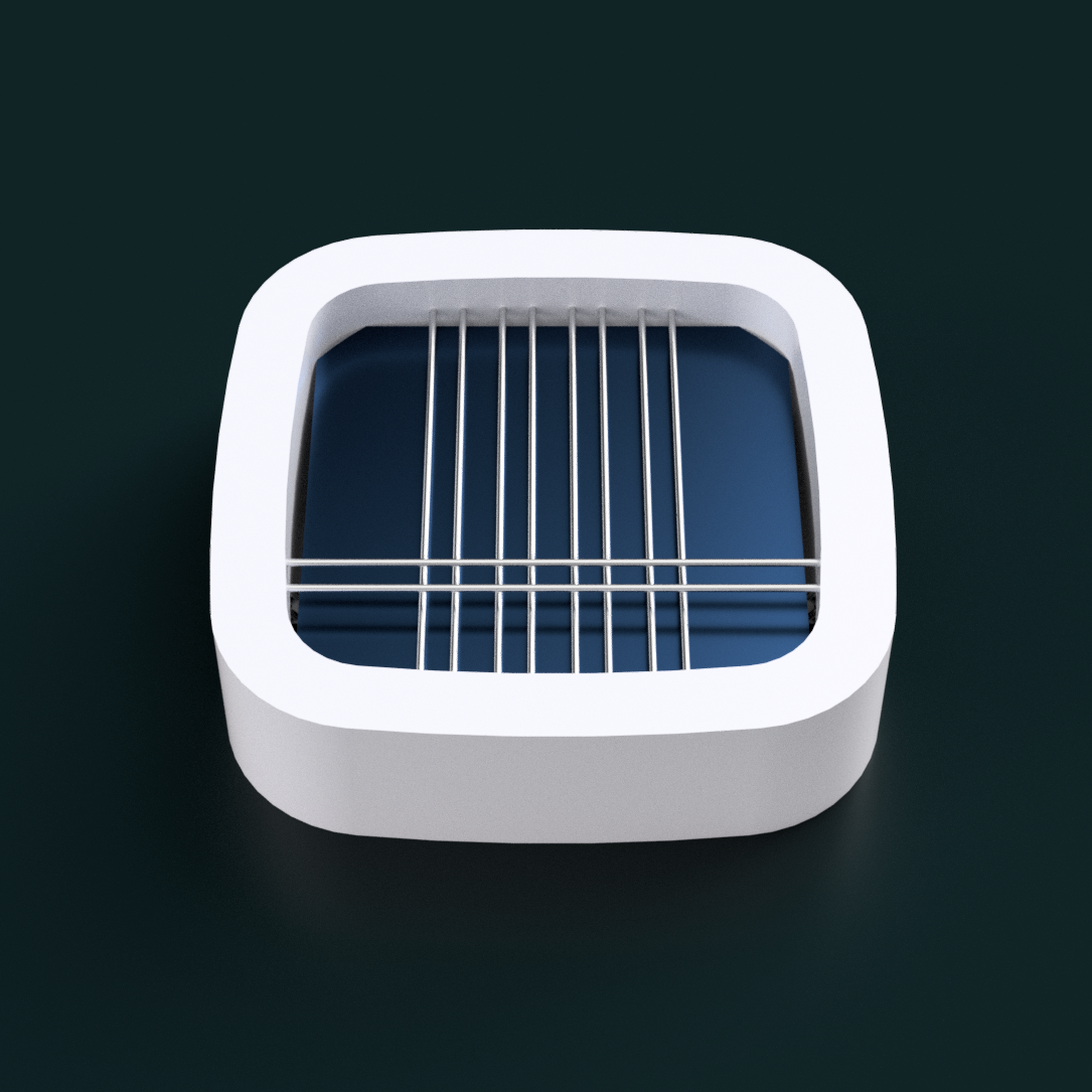
Instead of the planned 4.5mm, I've made the magnet spacing 4.65mm such that they perfectly align with a spacing of 18.6mm. I've also moved the thumb (horizontal) Tetrinsic down, partially for alignment and partially so that the finger (vertical) Tetrinsics have more usable space. Added cutout for the belts to go in and under the device. The underside, which has a simple but complementary design. Other than the concern about the white edges casting a shadow on the solar panel which is resessed by 16mm and that I still don't have a mounting solution, I think this concept is rather nice. It's solar charging, self sanitising, ambidexterous and should allow for thought-speed, distraction-free text entry.
[23:55] I just realised that this concept looks like the Nokia Suite app icon:
I was wondering why the design felt like it was a future-modern device from the early 2010s. I've also rounded the corners of the LCD cutout.
- Benefits mentioned for the Freewrite Traveller
-
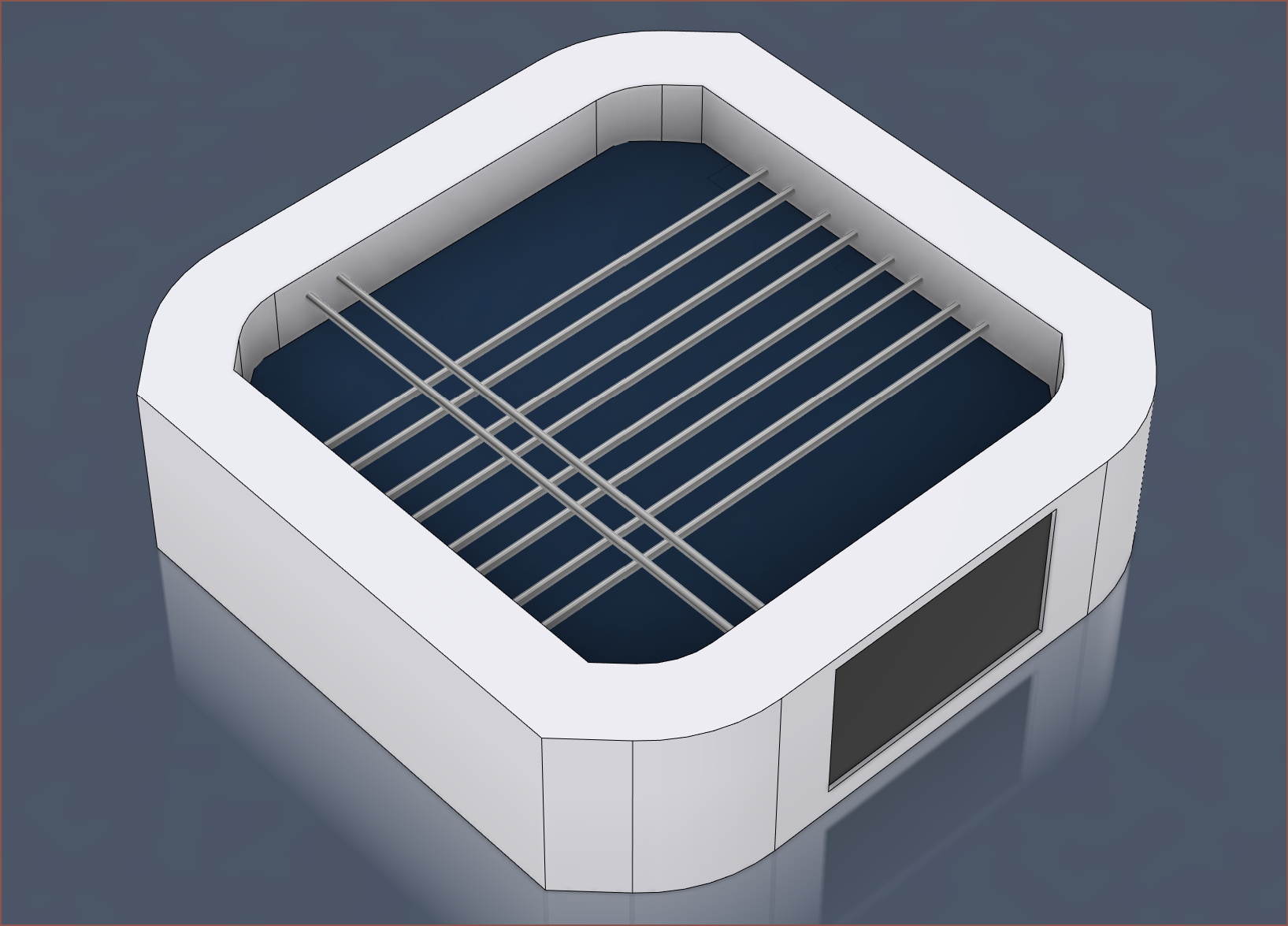
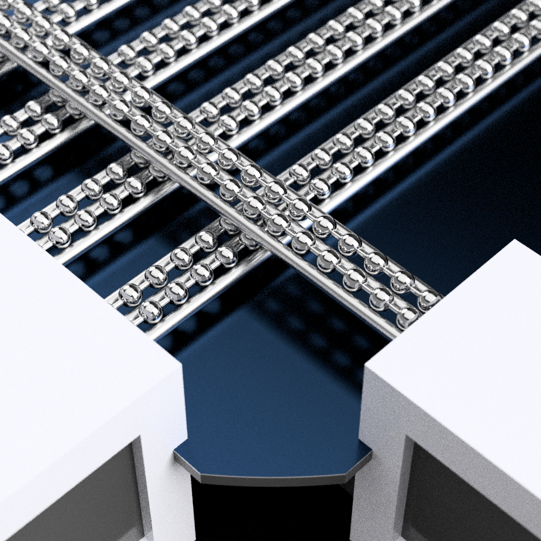
[E1][M] Concept with visible ball-chain
09/14/2023 at 22:35 • 0 comments[27 Aug 2023]
I've been modelling for about 3 hours (and it's now 3am), but as you can see, the only noticable difference is the fact that the ball chain is now visible and that there are actually slots for them, instead of just phasing through walls. The reason for this modelling time is because of Tetrinsic. Sourcing solid 1.5mm rods is more expensive and not as available as 2mm (on AliExpress) and I'm not too fond of the 2.0 safety rating from the 500g force simulation. Long story short:
- To keep the minimum wall thickness of the pressure collector as 1.2mm, I had to model slightly different geometries for the center and side rods and move the load cell up 1mm.
- The new rod configuration had to be applied to the pressure collector geometry.
- I then had to simulate it again, and I've got 3.2 safety rating in a tiny spot and 4+ everywhere else.
- I get 0.33mm of displacement, which balances out the increased rod size, allowing me to keep the 5.2mm offset.
Now all I have to do... is turn this concept into a reality. While I'm saddened that this device is so large, I'm glad that it actually looks so minimalist despite trying to be as good or better than 6 seperate input devices and be sustainably powered. I even watched an hour or two of artists drawing (both digital and paper) to better know what motions are usually performed.
I'm sure some mathmatician or engineer has said "something something simplicity something complexity", or something, like "the most beautiful equation" being e^(i*π) + 1 = 0. I doubt it was even remotely as simple as it appears to actually discover that equation.
The next step I would like to do is see if I can print a concept with sliding peices to better understand mounting positions and ideal screen locations.
[09:10, 27 Aug]
I've had to increase the squares to have sides of 40mm, but it also means that I can have a 2.4mm roof over the Thumb Tetrinsic whilst having its square touch the ground (no hovering or extension necessary". I've also thickened the white section from 5mm to 7mm. I think, after all the setbacks since discovering the turning radius issue of the 3.2mm ball-chain, I'm finally onto a winner here. You know, some "we're so back" energy.
New Renders:
-
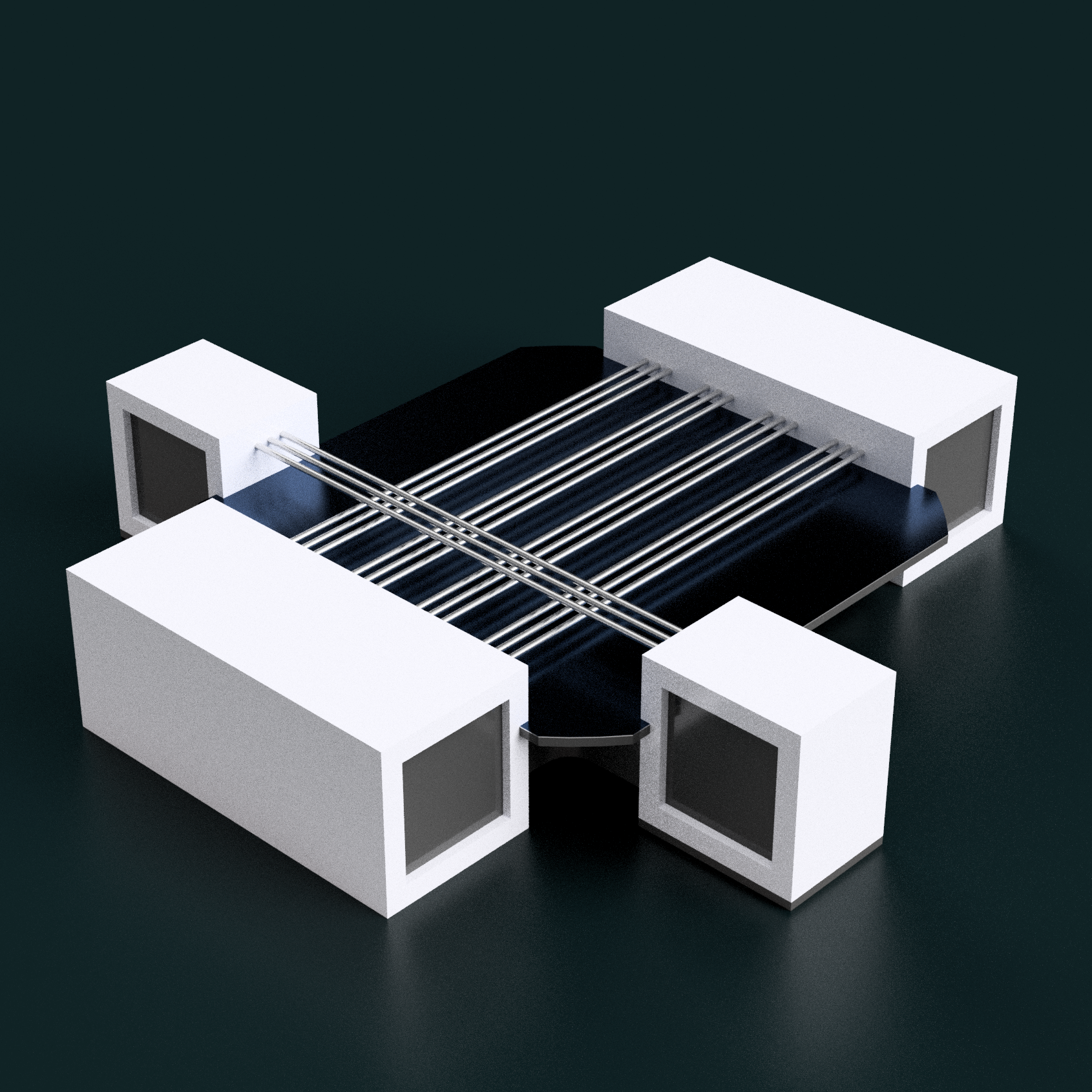
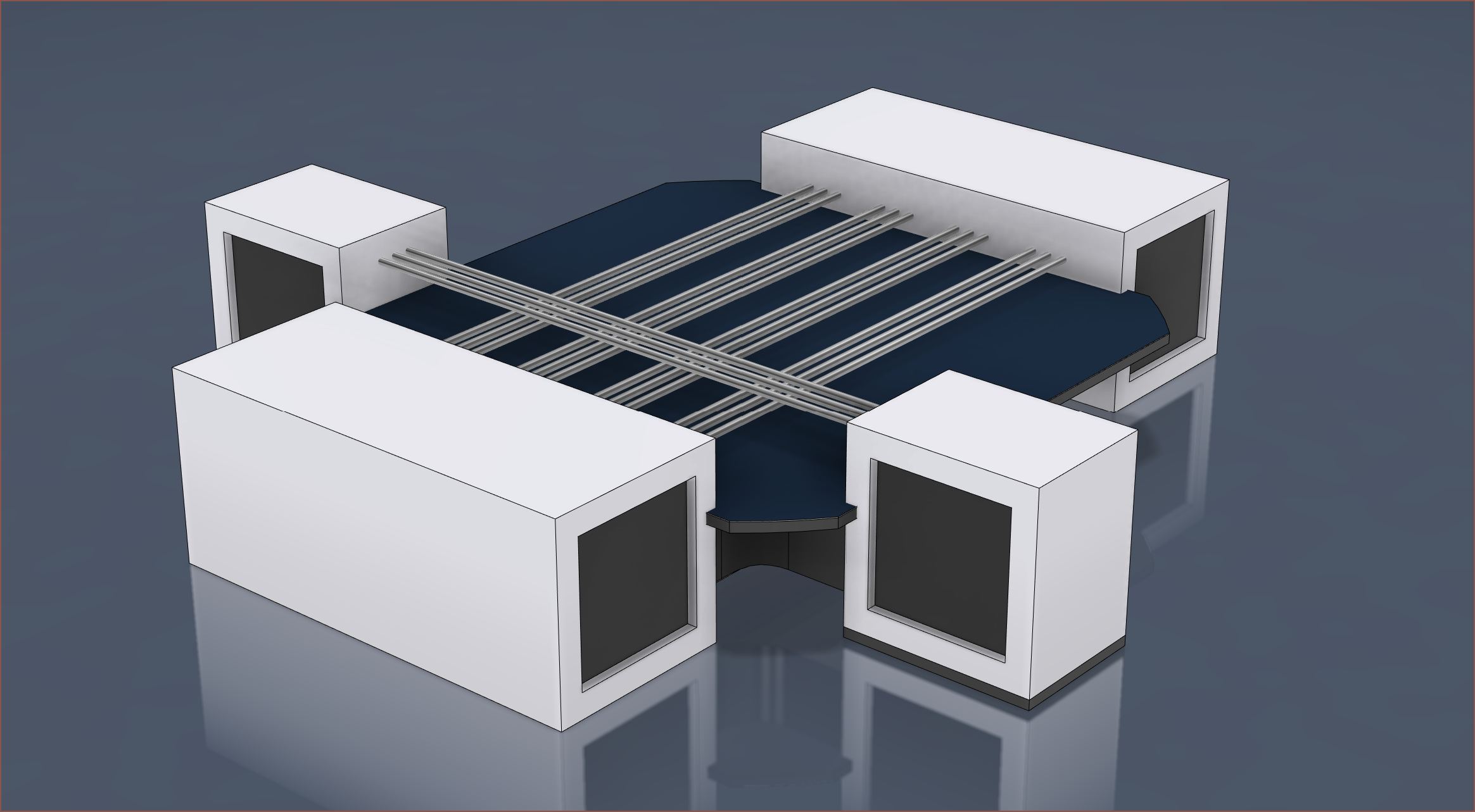
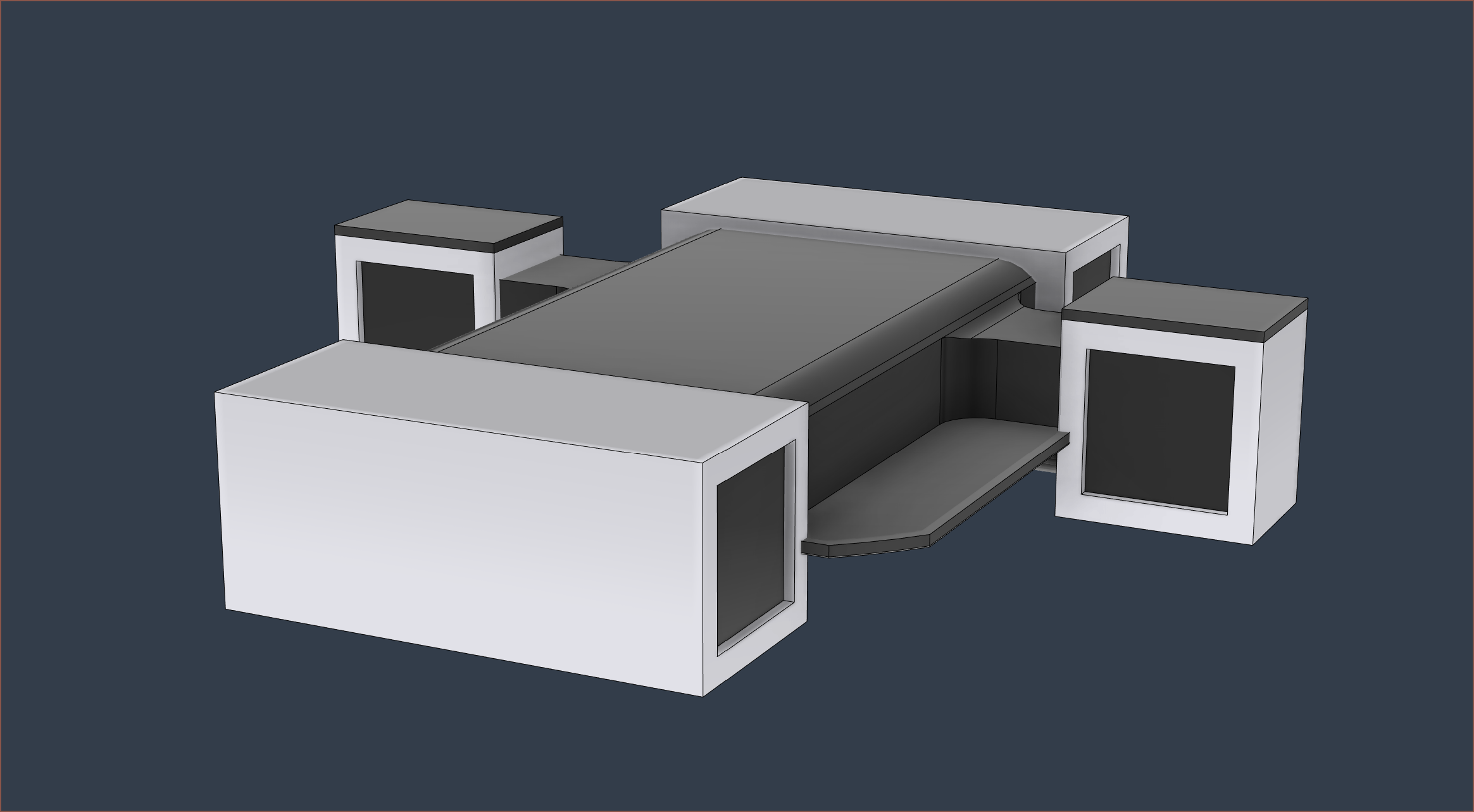
[M] Quickly modelled concept
09/14/2023 at 22:34 • 0 comments[25 Aug 2023]
I tried a few things, such as the left/right squares facing up (see below) but I eventually settled on this design. Due to the fact that the thumb #Tetrinsic [gd0041] is 5.2mm higher than the finger ones, I've had to lift the square up to compensate. I've made the extension a dark grey so that there's contrast between the elements, but I might just leave the squares "floating" instead.
This is the first attempt -
[E1][A] Reason behind the name
09/14/2023 at 22:33 • 0 comments[25 Aug 2023]
I didn't like the name Tetentaic, which is the merge of Tetent and "photovoltaic". After a few trials, and thinking about the names for Tetrinsic and Tetinventory, I thought of:
- Iridescent
- Incandescent
- Moon Crescent
as they all relate to light in some way.
It also still has some "Tetent" element: Tetrescent
[14 Sep 2023]
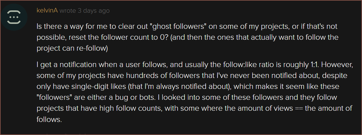
Project duplicated due to Hackaday follower bug. Original project creation date: 25 Aug 2023
This is what I posted to Hackaday feedback:
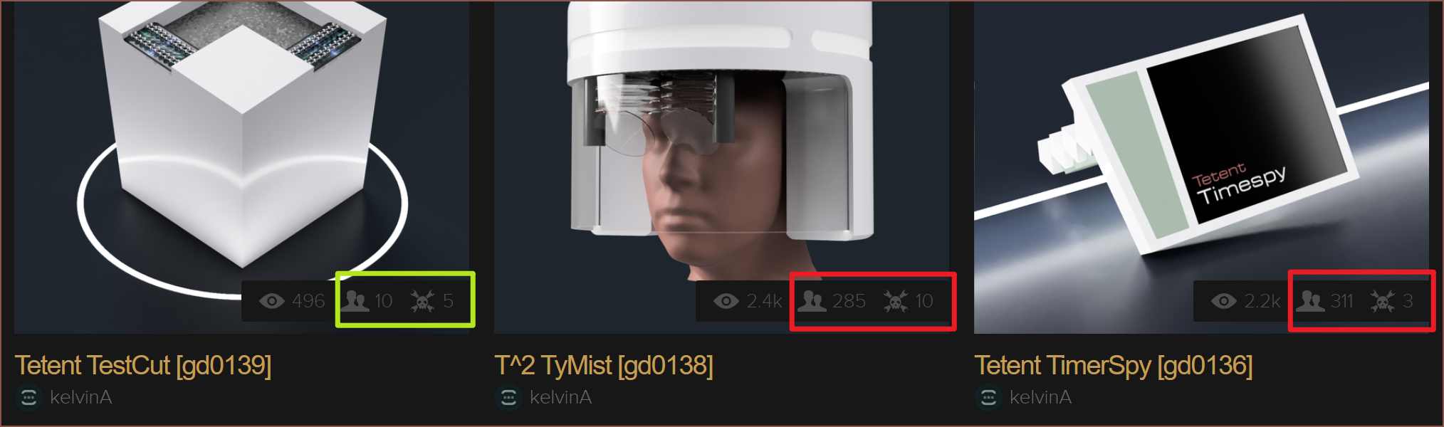
The below image shows what I'm talking about:
TestCut has an expectable number of followers, given the amount of likes. It's suspicious when there's 300 followers for the other two with likes barely hitting the 2-digit mark. I thought I'd just duplicate now while this project is still relatively young.
Tetrescent [gd0150]
The solar powered replacement of my keyboard, mouse, game controller, drawing tablet, MIDI, PDA and spacemouse.