After same break I wanted to continue but I noticed I lost the small magnets :-(. Reordering them and redesigning the cap went well. Gluing is horrible because they are so tiny.
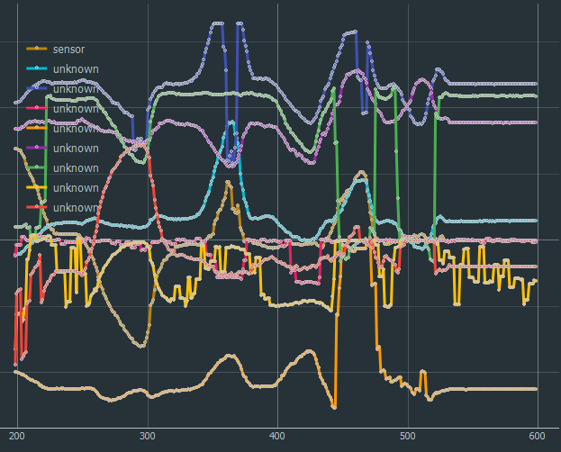
And I also succeed to have the furst Python/TKinter/Bleak setup running giving about 50Hz Update Rate over BLE :-). The measurements showed that the magnetic field changes from the knob displacement (arround sample #1000) are a bit less than these of the earth magnetic field (sample #1500ff) but no signal saturation at all. I used again the stiff springs and they are for sure to stiff but should not be a problem for these first tests.
But most important I found the final name of my device, it will be called *Galaxy6D* :-) Had to changer some links but hope this name will stay till the end :-)
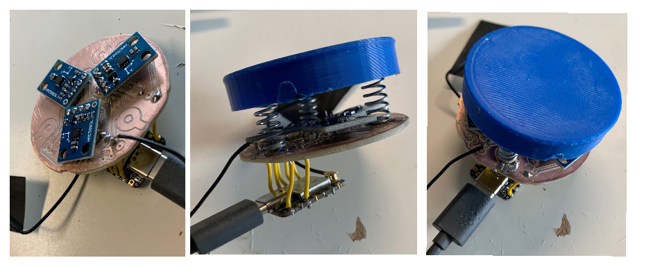
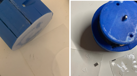
I added a silicon piece at the bottom of the knob to increase the friction (plastic was quite slippery on my table) and now it seams to be quite good (left picture). The much smaller magnets also arrived and they are really tiny (right picture in the bags, 2x1mm and 1.5x0.5mm, NdFeB N48, 1.42Tesla). When trying them out I nearly lost them. I have to design a new top for them to be able to mount them properly.
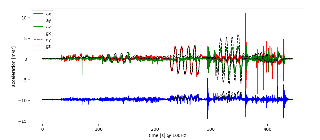
Next I tried to use the acceleration sensors to estimate the linear displacement by double integration (acceleration--> velocity-> displacement) but found out this will not be so easy. After soem strange results I estimated the aceleration, 1Hz moving the head with about 5mm displacement would give an acceleration of (2*pi/s²)^2*5mm = 0.2m/s² which is not too big for the used measurement range setting of 2g (~200m/s²). I recognized also, that very small rotations will lead to measure the change of the earth gravity field in much higher magnitudes. Following charts shows the measured acceleration (ax,ay,az) and the estimated acceleration caused by the earth gravity field (gx/gy/gz) by teh rotation of the top.
The black dashed lines are the main contribution of total measured acceleration. And even by integrating the offset compensated accelerations, the velocity and displacement had to much other effects as to see the linear displacement. With good eyes, one can see the velocity changes in the first three phases (20s ... 220s) but latest with the displacement, the integration error made everything invisible. How to continue ..... don't know yet ...
Good discussions with my hidden co-creator made clear that there are three to four possible options to follow to derive the conversion matrix from the 3x3D magnetic sensors to teh 6D displacement of the know:
Use simulation to derive converstion matrix
Use a mechanical defined displacement (i.e. in a kind of end stops, an external actuator, ...) to have a mechanical defined displacement and use these defined positions to calibrate the conversion matrix
Use the IMU in the TOP to estimate displacement and derive from this the groudn truth to derive the conversion matrix
Use the pure measurement data and statistical analysis (i.e. a principal component analyisis: PCA) to derive the conversion matrix from the magnetic sensors to the displacements
Simulation would probably be the easiest but I am note sure if this would be exect enough. mechanical would be the most precise but possible a lot of effort. The IMU could work (at least for the three rotations but might have additional errors by the IMU (especially when integrating the rate signals or even the accelerations twice. The pure statistical approach might bee the most elegant one, but probably quite hard and maybe not accurate enough.
I am myself not sure what to to next, so stay tuned and follow the next results !
[some hours later ... ]
PCA did not really work, but using the IMU at least for the rotation axes did not give too bad results (not at all finished but a good way to continue!):
Description
left: the 3x3D magnet signals for the test recording, where i sub-sequential moved the top in all degrees of freedom
middle: the integrated angular rate from the IMU in all three dimensions I used as ground truth for the regression
right: the resulting estimate of the top movement only based in the magnetic sensors (and of course the regression result)
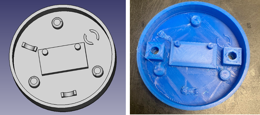
Since the first step was working now without the top, I redesigned a the top to add a mounting for the IMU and hole to screw in a possible cover later:
Then I used some UV curing paint to protect the copper around the spring mounts for short circuits:
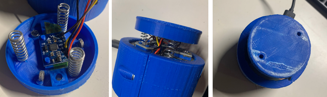
And finally I glued in the magnets as well as the IMU and sticked the feathers to the pins. Then soldering the Top to the PCB finished the build process.
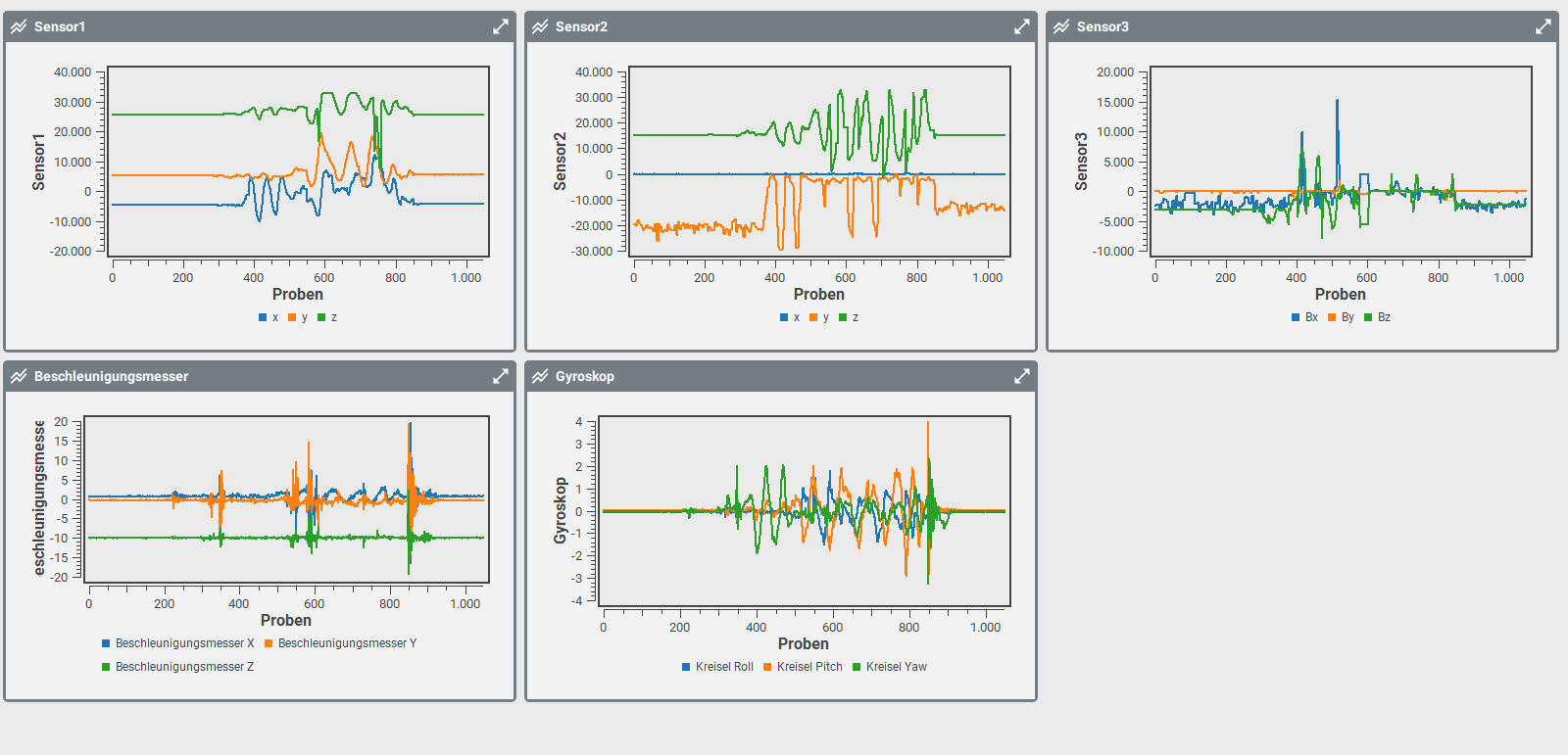
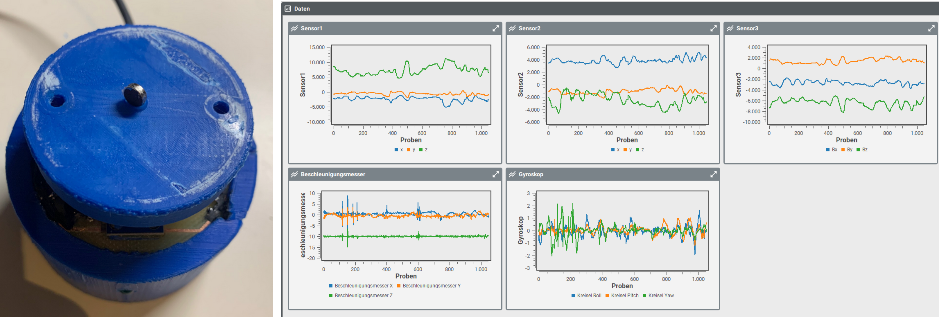
And then turning it on, signals from all sensors arrive! Data I can work with
Findings:
springs had been definitvely much to strong. Despite the weight I basically move always the full knob and not the top only.
The signals of the magnetic sensors semas somehow again strange, maybe saturation effects or sinbgularities in the field ? Something I have to investigate more closely [Update: confirmed, simulation gave me >2mT which is >20GAUSS way more than the sensors can measure .. I have to ordner much smaller magnets ...]
one sensor stuck at 0 (2-blue),
one very low signal (3-orange),
two with sudden jumps (3-green, 3-blue)
some signals very noisy (2-orange, 3-blue)
[Update - Quickfix]
Softer springs & single magnet on top of the top :-) ==> Touch and feel much better and no signals in saturation. Possible something to play until the smaller magnets arrive :-)
or more systematically the output of megnet sensor #1
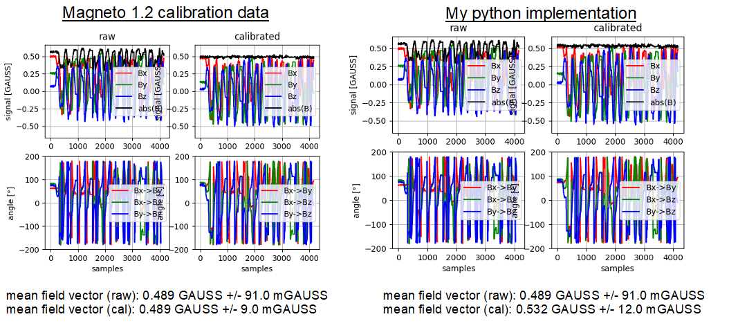
Searching the internet for magnet field calibration, I found a very good overview paper . However to start, I used the nice tool Magneto 1.2 to calibrate one of my sensors. It worked quite well and the variation in the absolute magnetic field ( =sqrt(|Bx^2+By^2+Bz^2) ) reduced signiciantly.
I tried to re-implement in python since the sources had been in c and not complete. Quite handy was the source from TiltyIMU which helped me a lot and finally I succeded to transform the red measured data in the calibrated green data.
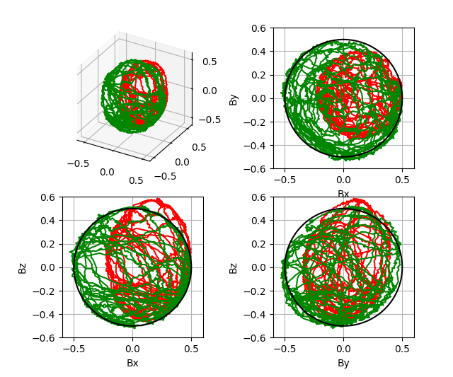
Finally, rotating the sensors by a fixed 120° (as layouted on the PCB) gave me a very nice match:
Since the setup was reasonable stable, I was able to measure alll three sensors at the same time and turning the base in all directions. In the picture below, you can see the time signals of the three sensors for all three axes (upper row), projections in XY/XZ/YZ dimensions of the measurements in the middle row and a full 3D plot of the fieldsI measured ~27s and had in total ~4200 measurement points which was above 100Hz. But since I did not take any timing measures on the ESP32 and did probably not configure the sensors correctly, I am not sure if the timing is perfect. Foir each measurement I calculated the absolute of the field vector (=sqrt(Bx^2+By^2+Bz^2)) and averaged it giving me an absolute earth magnetic field at my desk of about 0.5G (= 50uT) which seamed reasonable. The standard deviation of the measurements was <0.1G. Doing this standard deviation calculation without movement, resulted in a value <0.01G, so most of the noise resulted from the movement/timing/other effects.
SInce I can now measure 3 times the earth magnetic field, I should be able to calculate it only from one sensor and subtract it from the others so that I have two sensors without the earth magnetic field.
To avoid the cable and be even more flexible to debug, I also tried to switch to WLAN, but it did not work. The "hacked" I2C bus seamed to be confused by the multithreading of the WLAN (ESP32S uses the other core for WLAN handling). So one more thing to solve.
Learnings / ToDo's:
I did not move the base in all directions. Looking to the 3D plot one can see (OK, much better when rotating it online) that there is an 1/8 sphere not covered. Will be better with pure battery powered.
Main todo derive an analytic formula for the three sensors. Not necessarily to o this then explicitly since I planned to use a Kalman filter anyhow.
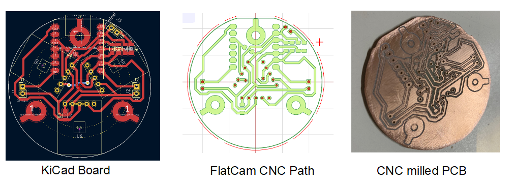
The full setup was a bit fragile to debug so I decided to do a design iteration. First Step was to update the PCB by
adding some space at teh sides to allow mounting
added battery connections, switches and LED as well as 6D IMU connection
a cleaner milling process by also clearing the intermediate copper areas
and still single sided to make milling easier ...
Then I designed distance blocks to let the magnetic sensors be glued to the PCB. This worked quite nice The ESP32S3 I mounted the same way, included the two wires for the battery connection (which had been rotated :-( in the design): Then the base mount design followed; threaded inserts to but two half blocks together. Inside the metal weight block, the battery and on the top the PCB. The Base holds also the LED and the power switch. The push buttons and the IMU I plan to mount in the head. In general it worked quite good, the only problem was that the dimensions had been to small (shrinkage of the ABS I used?) and I had to print three times and still the base slightly broke. BNut sufficient to continue testing. You can see the LED in the middle picture and the battery on/off switch on the right hand side picture. Learnings:
housing dimensions not yet sufficient
Antenna had to go on top of the battery, I will have add a compartment where I could put the antenna on the outside.
Doing some test, I found that at least one channel seamed not to work (Sensor 2, blue). Also by moving the whole know in the earth magnetic field, the signal did not
Then I printed a fast fixtured I had ten to tighten with tape. The fixture holds a 60m diameter 10mm high metal block. Fixture was not too bad, maybe a bit to stiff. I will have to design a better housing and then test again.
Then I did some more test, and contradictional to my first findings, there was significant less signal when I displaced the complete knob in x/y direction on the table. Only by rotating the complete knob I got some signals: What still does not seam to be wrong is the transformation of the units. Convertig the rotation in all 3 axis I would assume to have about 30 to 60mT amplitude (the earth magnetic field. Values seamed to be much less, I might need to debug my test software here a bit more.
I did some calibration measurements by rotating the knob only in one direction and doing a principal component analysis just using the first component for each of the measurements as a projection matrix
Not directly visible but I can tell you the first component (yaw) worked very nice. The plot was highly correlated to my movement of the know. When the other come in play, I recognized that there was a lot of cross talk. Then I recognized that the signal change when I move the whole know around the space ... oh yes earth magnetic field .... damn ... I plotet the raw signals from the simulation and recognized that the signals had also been in the range of the earth magnetic field (about 0.05mT): So how to solve it, in principle I have 9 measurements and 9 degrees of freedom (3 rotation and 3 displacements of the know respectively and 3 of the magnetic field). OK, since my sensors are not on the same position, one could argue that I even have 6 degrees of freedom of the whole device in space. How to continue:
doing a highpass filter to remove the earth magnetic field
adding 3 degrees of freedom to my calibration
moving the magnets more closer that the induced field is much stronger than the earth field
 BastelBaus
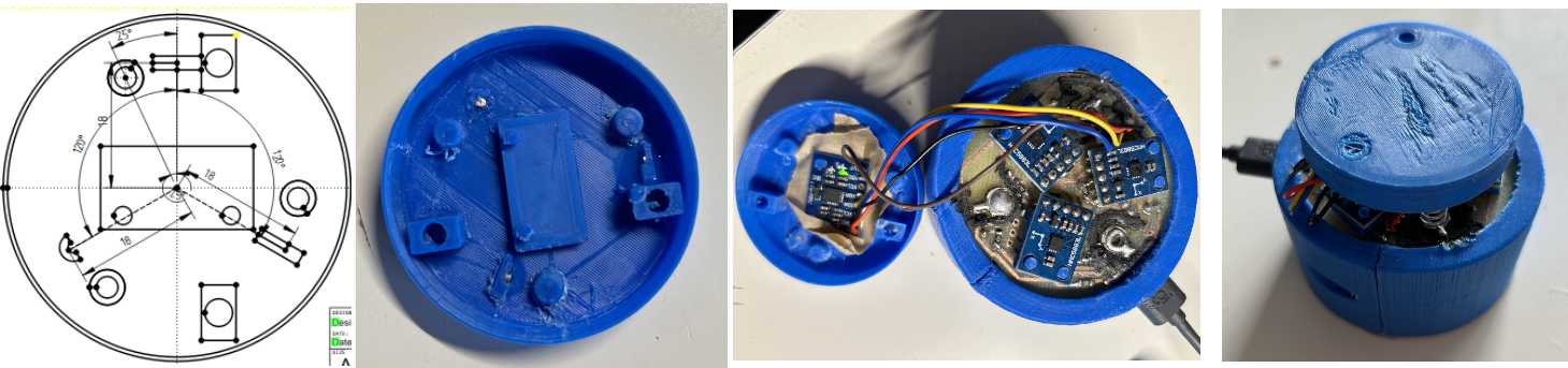 And I also succeed to have the furst Python/TKinter/Bleak setup running giving about 50Hz Update Rate over BLE :-).
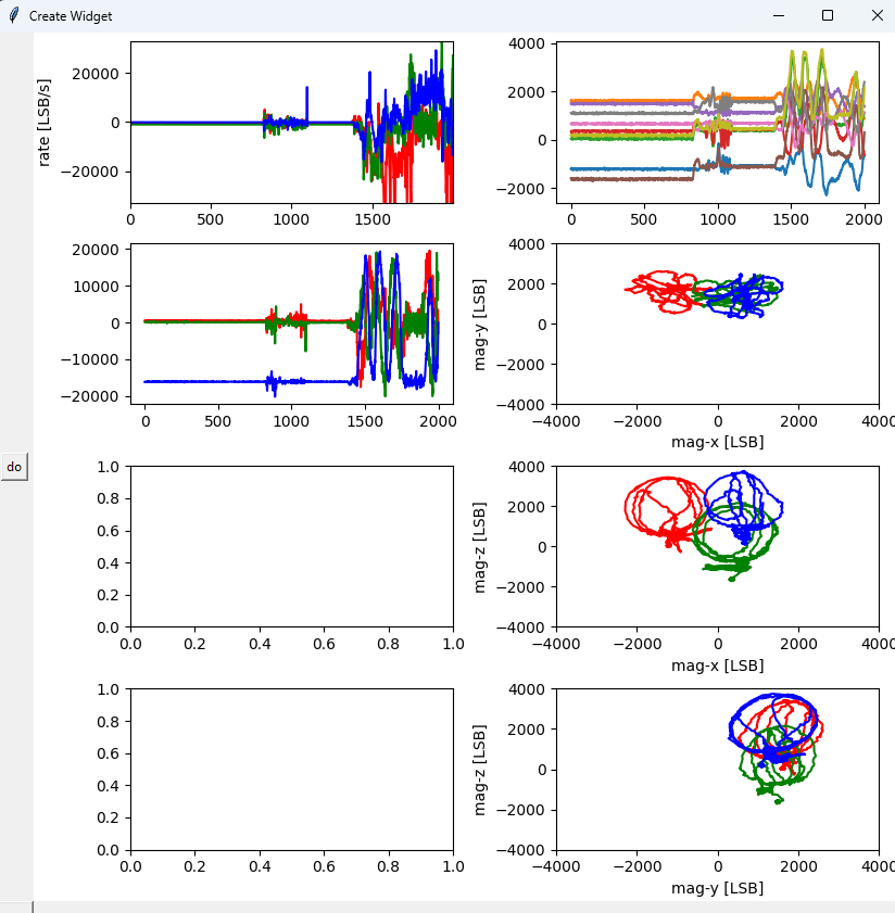
 The black dashed lines are the main contribution of total measured acceleration. And even by integrating the offset compensated accelerations, the velocity and displacement had to much other effects as to see the linear displacement. With good eyes, one can see the velocity changes in the first three phases (20s ... 220s) but latest with the displacement, the integration error made everything invisible.
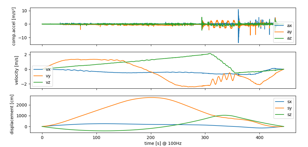 How to continue ..... don't know yet ...
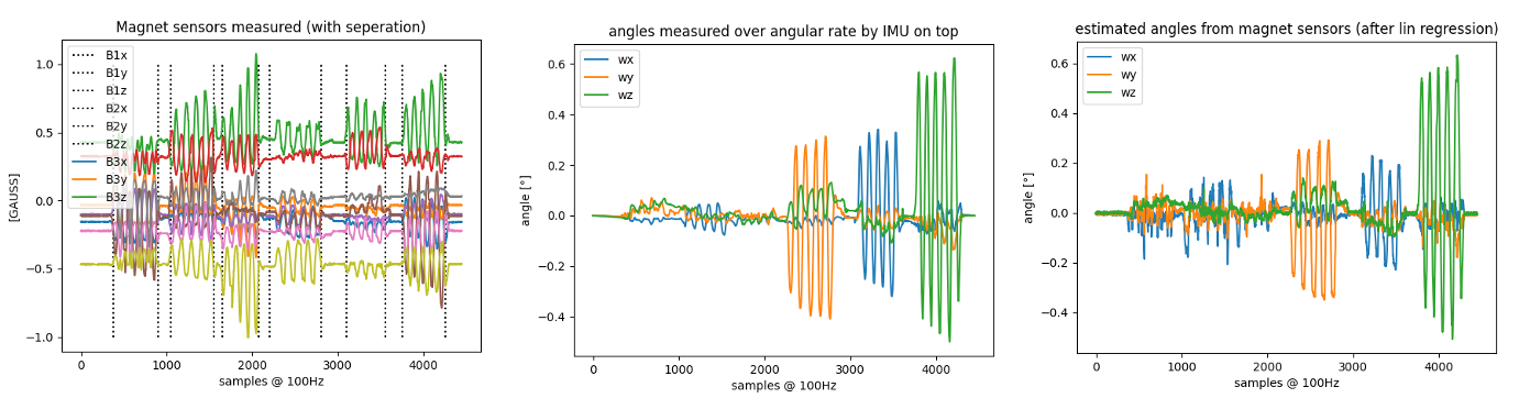 Description
 Then I used some UV curing paint to protect the copper around the spring mounts for short circuits:
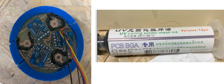
 or more systematically the output of megnet sensor #1
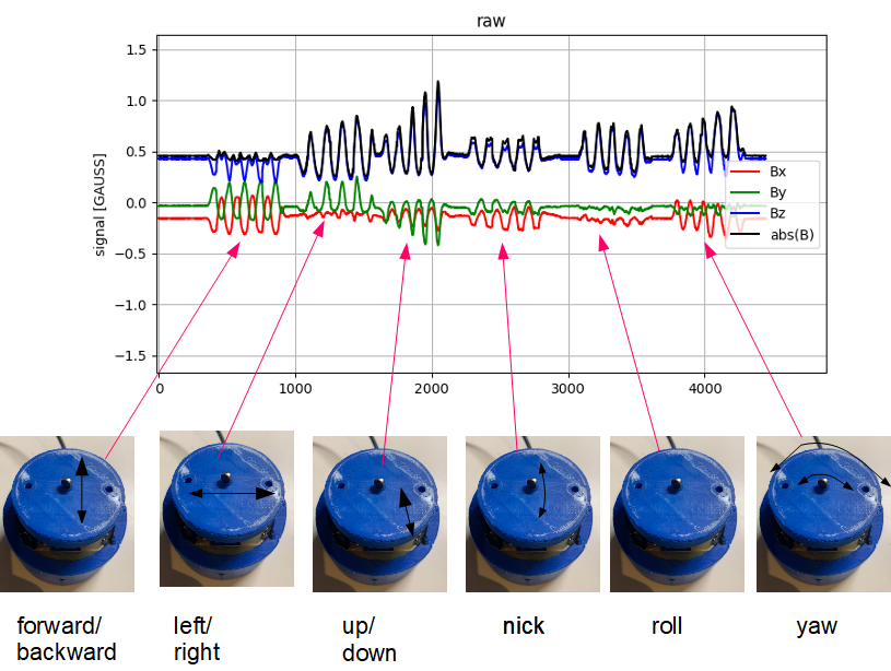
 Finally, rotating the sensors by a fixed 120° (as layouted on the PCB) gave me a very nice match:
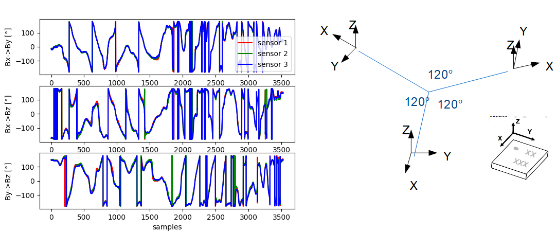
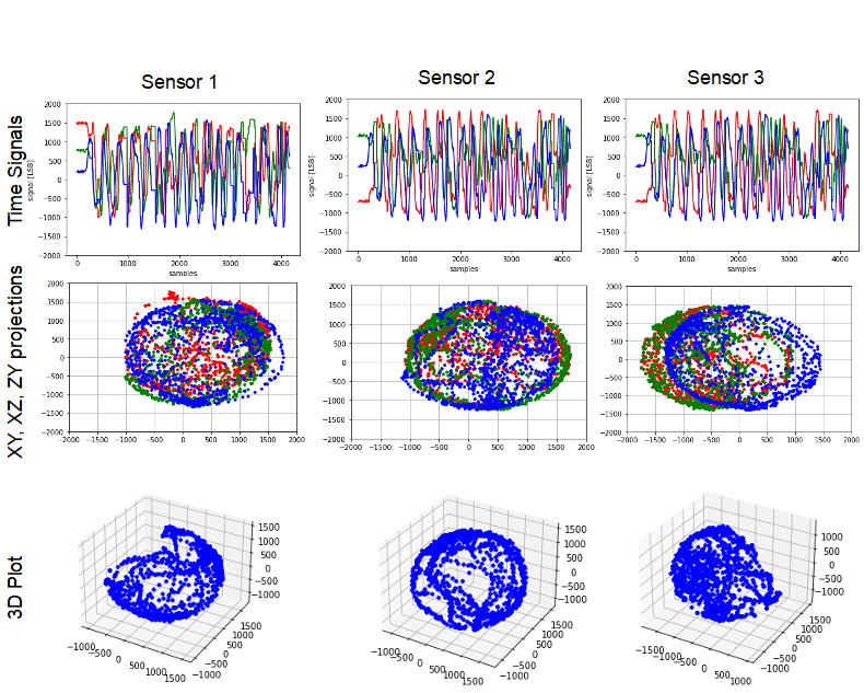 I measured ~27s and had in total ~4200 measurement points which was above 100Hz. But since I did not take any timing measures on the ESP32 and did probably not configure the sensors correctly, I am not sure if the timing is perfect. Foir each measurement I calculated the absolute of the field vector (=sqrt(Bx^2+By^2+Bz^2)) and averaged it giving me an absolute earth magnetic field at my desk of about 0.5G (= 50uT) which seamed reasonable. The standard deviation of the measurements was <0.1G. Doing this standard deviation calculation without movement, resulted in a value <0.01G, so most of the noise resulted from the movement/timing/other effects.
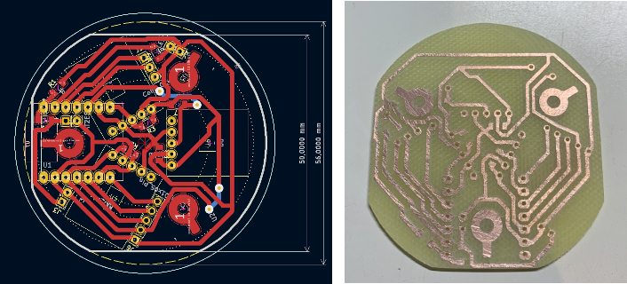 Then I designed distance blocks to let the magnetic sensors be glued to the PCB. This worked quite nice
 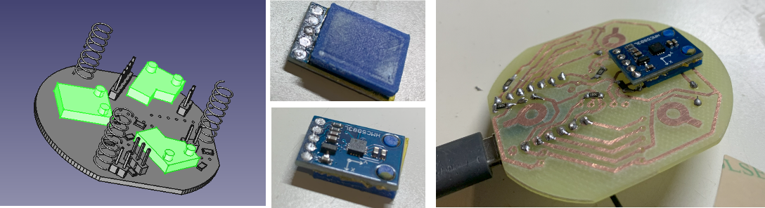 The ESP32S3 I mounted the same way, included the two wires for the battery connection (which had been rotated :-( in the design):
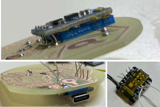 Then the base mount design followed; threaded inserts to but two half blocks together. Inside the metal weight block, the battery and on the top the PCB. The Base holds also the LED and the power switch. The push buttons and the IMU I plan to mount in the head.
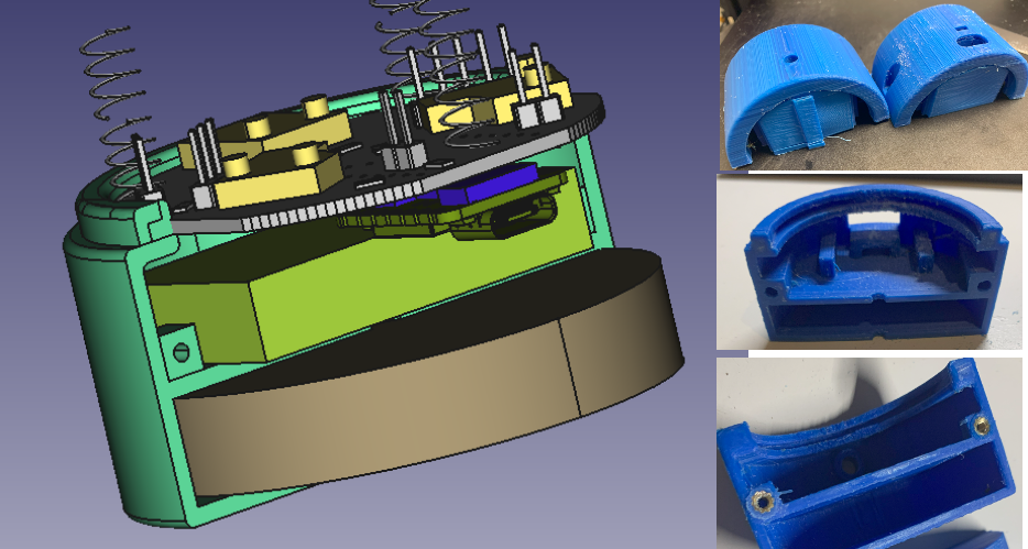 In general it worked quite good, the only problem was that the dimensions had been to small (shrinkage of the ABS I used?) and I had to print three times and still the base slightly broke. BNut sufficient to continue testing. You can see the LED in the middle picture and the battery on/off switch on the right hand side picture.
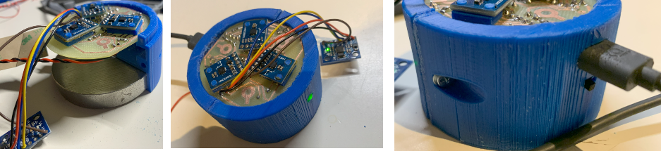 Learnings:
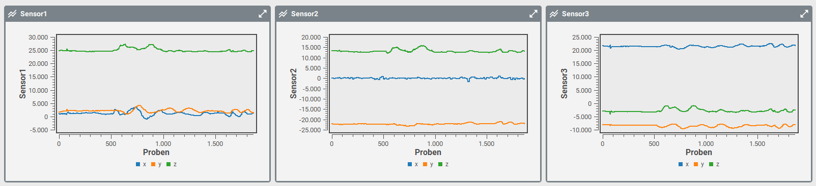 Then I printed a fast fixtured I had ten to tighten with tape. The fixture holds a 60m diameter 10mm high metal block. Fixture was not too bad, maybe a bit to stiff. I will have to design a better housing and then test again.
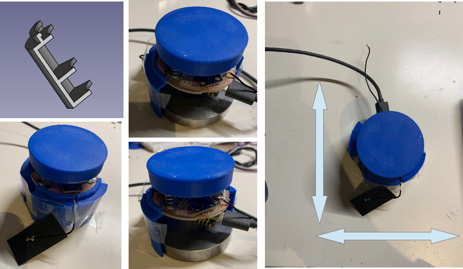 Then I did some more test, and contradictional to my first findings, there was significant less signal when I displaced the complete knob in x/y direction on the table. Only by rotating the complete knob I got some signals:
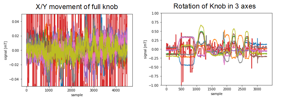 What still does not seam to be wrong is the transformation of the units. Convertig the rotation in all 3 axis I would assume to have about 30 to 60mT amplitude (the earth magnetic field. Values seamed to be much less, I might need to debug my test software here a bit more.
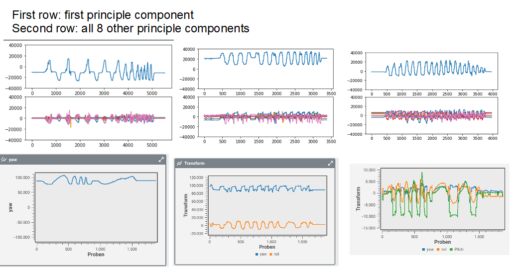 Not directly visible but I can tell you the first component (yaw) worked very nice. The plot was highly correlated to my movement of the know. When the other come in play, I recognized that there was a lot of cross talk. Then I recognized that the signal change when I move the whole know around the space ... oh yes earth magnetic field .... damn ... I plotet the raw signals from the simulation and recognized that the signals had also been in the range of the earth magnetic field (about 0.05mT):
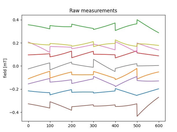
 And the 3D printed Knob with the magnets:
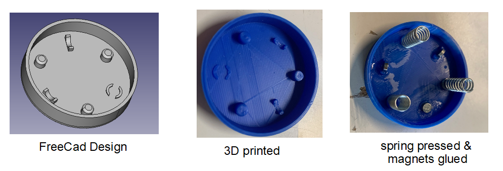 Building all together: