| GER layout | 
|
| ENG layout | 
|
General Idea
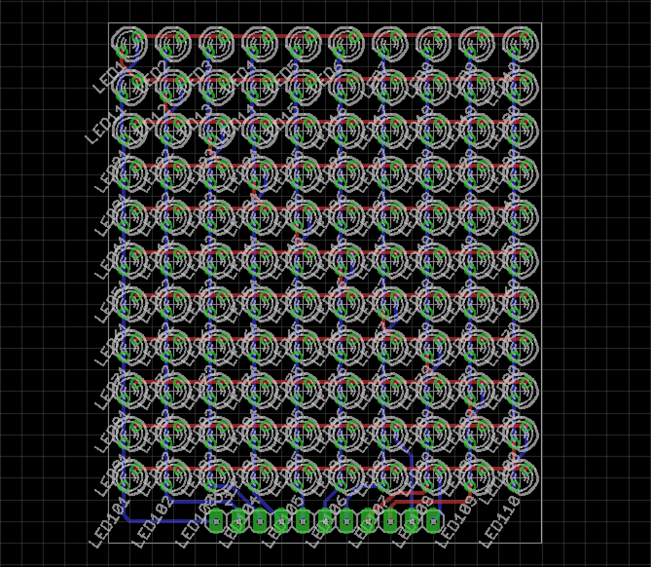
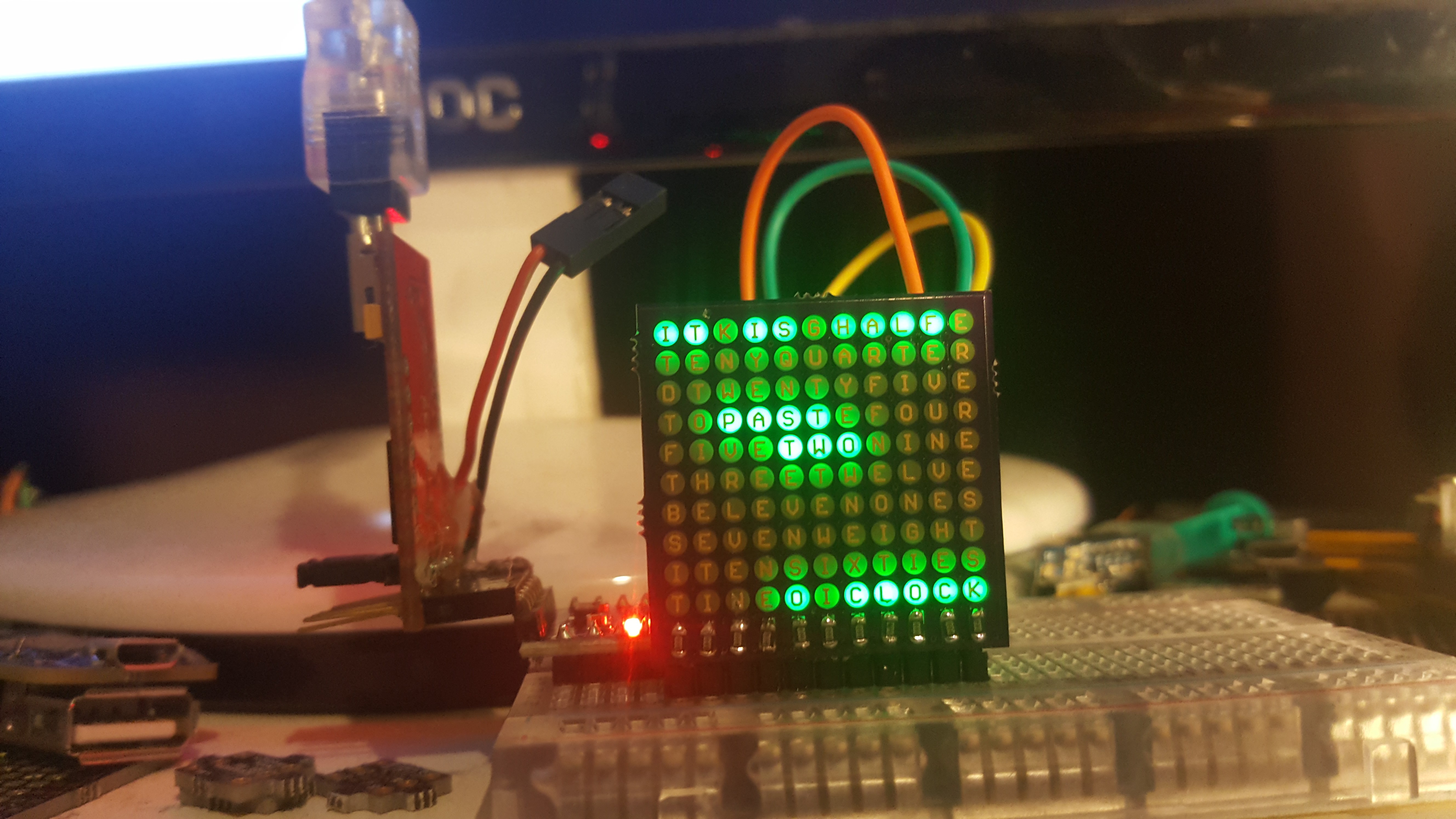
@Radomir Dopieralski mentioned in #Hacker Channel that one could use LEDs backwards to shine through the PCB and at this point I'm not sure if he mentioned charlie-plexing and word clock as well, but let's just say I was inspired to design a board like this. At this point I already had a board prepared, a 10x11 LED matrix with 5mm charlieplexed LEDs. Charlieplexing can get very confusing, but I found a trick online [research link], that helps a lot to layout a matrix. Instead of controlling it with 10+11 pins this will take only 11 pins.
LED footprint
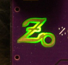
From there I've edited an LED footprint in EAGLE so that I was able to just change the LEDs without rewiring the schematics. The blue circle is on the layer "42 bRestrict" - this will stop the polygon on the bottom layer from putting copper there. At the same time the copper will frame the letter. Since I'm an expert in soldering LEDs the wrong way by accident, I will use standard 0603 LEDs, instead of special "bottom mount" LEDs. On the top Layer of the LED footprint is a smaller, rectangular shaped Object on "41 tRestrict" that's supposed to let the light through as well. The letters where placed on the bottom layer.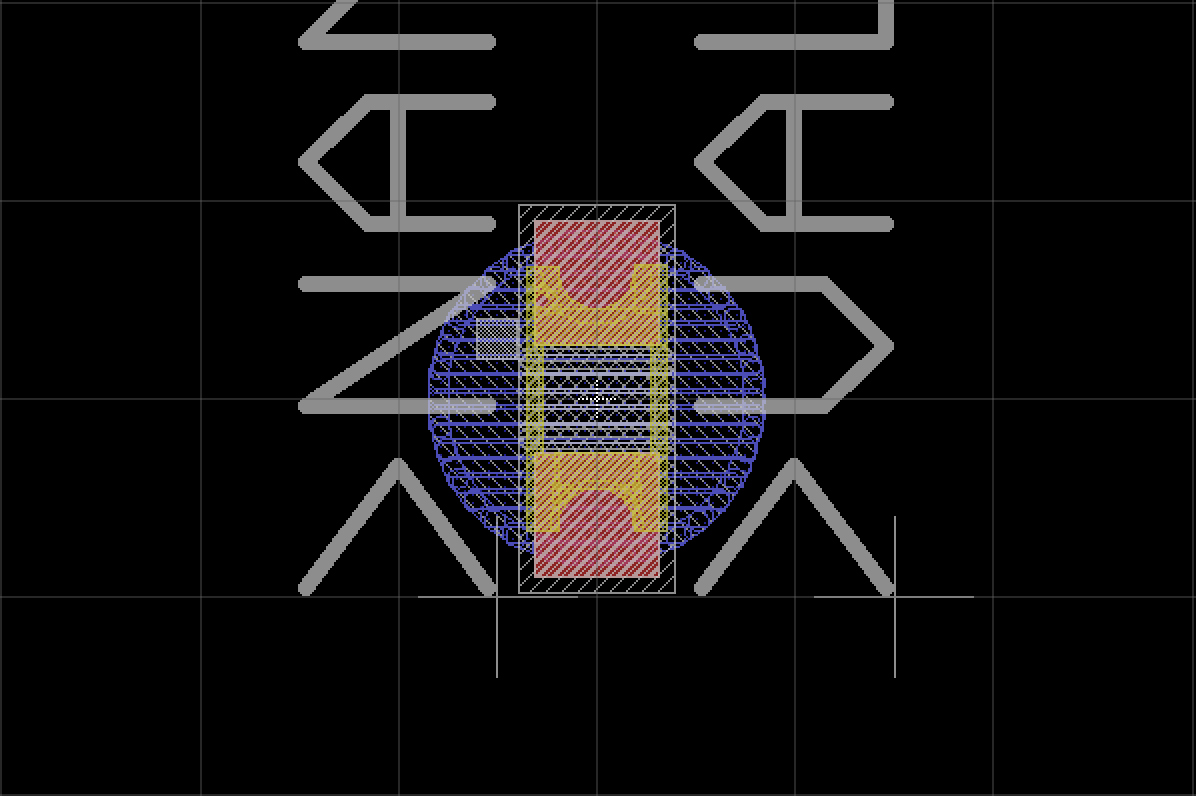
What's Charlieplexing
It's always good to try to explain stuff in your own words, legally speaking as well. Blinking LEDs is always awesome, because it's wysiwyg. Connect the anode to 5V, the cathode to GROUND and it explodes. Add a resistor and everything is great, as long as it's the right value. The other way around they do cool stuff too, but not important for this project. Here it's important that they're not glowing.
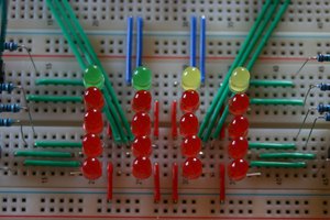
The cool thing about ATMEGA chips is, that they can source/drain enough power to make LEDs blink and that they're on Arduino boards. You can even put two opposing LEDs on the data pins and and make them blink depending on the OUTPUT of the pins.
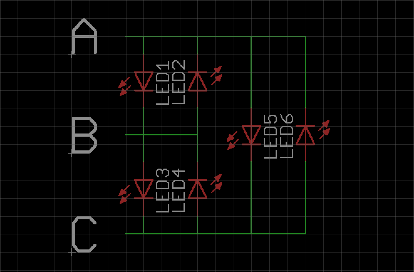
Given this schematic and you only have ground and power, then this would be your truth table. Adding more LEDs would only add more LEDs that shine simultaneously.
| A | B | C | LED1 | LED2 | LED3 | LED4 | LED5 | LED6 |
| 0 | 0 | 0 | ||||||
| 0 | 0 | 1 | ON | ON | ||||
| 0 | 1 | 0 | ON | ON | ||||
| 0 | 1 | 1 | ON | ON | ||||
| 1 | 0 | 0 | ON | ON | ||||
| 1 | 0 | 1 | ON | ON | ||||
| 1 | 1 | 0 | ON | ON | ||||
| 1 | 1 | 1 |
Luckily the ATMEGA has a third state, a high impedance state - also called Z state. You can achieve that by turning the pin to an INPUT pin. The following table only shows how to activate the LEDs.
| A | B | C | LED1 | LED2 | LED3 | LED4 | LED5 | LED6 |
| 1 | 0 | Z | ON | |||||
| 0 | 1 | Z | ON |
|||||
| Z | 1 | 0 | ON | |||||
| Z | 0 | 1 | ON | |||||
| 1 | Z | 0 | ON | |||||
| 0 | Z | 1 | ON |
Pros and cons
So why all this? It saves pins and doesn't take much power! But I will have to worry about brightness and programming it, once the boards are here.
 davedarko





 Steven Roch
 agp.cooper
 tinandjar
Do you maybe still have that "[research link]" from the description somewhere?