-
Week #9
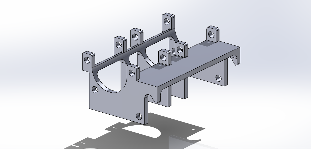
05/27/2024 at 15:23 • 0 commentsIn today's class, we assembled the train with the motor into the support piece we designed in the previous class. However, we did not consider the placement of the motor beforehand, so we had to perform reverse engineering to determine where to place the motor so that it would have enough torque to turn it. We have redesigned a compact piece to fulfill this function and also to hold the axis that moves the drive gear, ensuring that it remains properly aligned in its place.
![]()
Support piece where the motor is mounted, featuring a geometry that locks the drive gear's shaft in position, preventing it from moving upward or coming off the axis
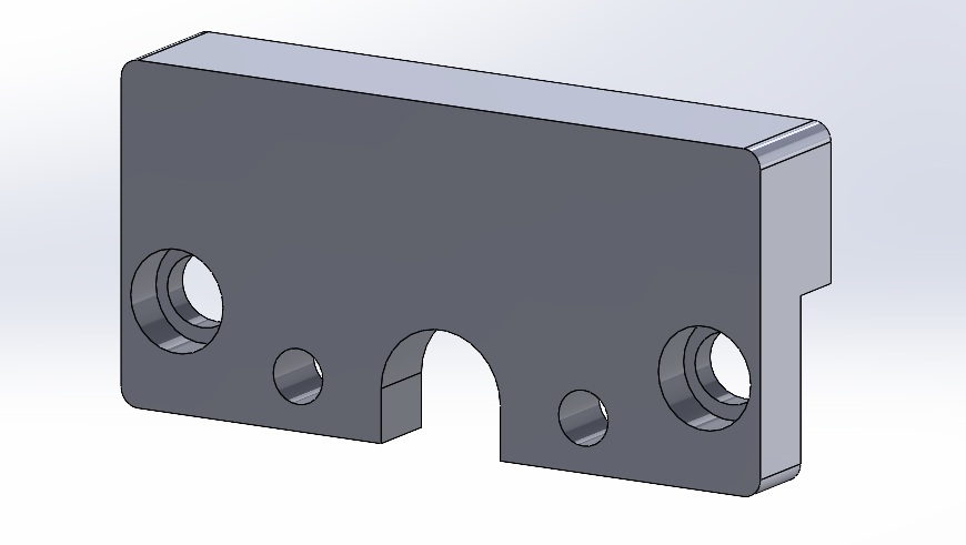
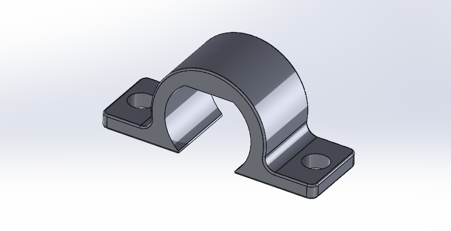
Furthermore, when testing the functionality of the train, we detected that the big motor that moves the whole device, rotated in its own axis, making the wires tangled and eventually not performing well enough with the gears at times. As for solving this problem, we redesigned the following piece below. This piece now secures the big motor, making the motor completely fixed even in its own axis. As you can see has two sets of holes. The inner holes are for inserting screws to prevent the motor from rotating around its own axis. The outer holes are for screwing the piece to the base where the motor is mounted. Additionally, we made a "counter sunk," which is a type of recess that allows the screw to be hidden. We did this because if the screw was not hidden, the drive gear would rub against it while turning, preventing the wheels from rotating properly and causing the motor to get stuck as well.![]()
Piece that secures the main motor from the wheels
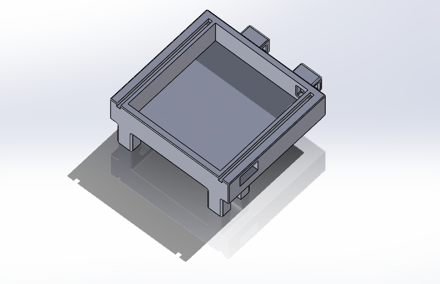
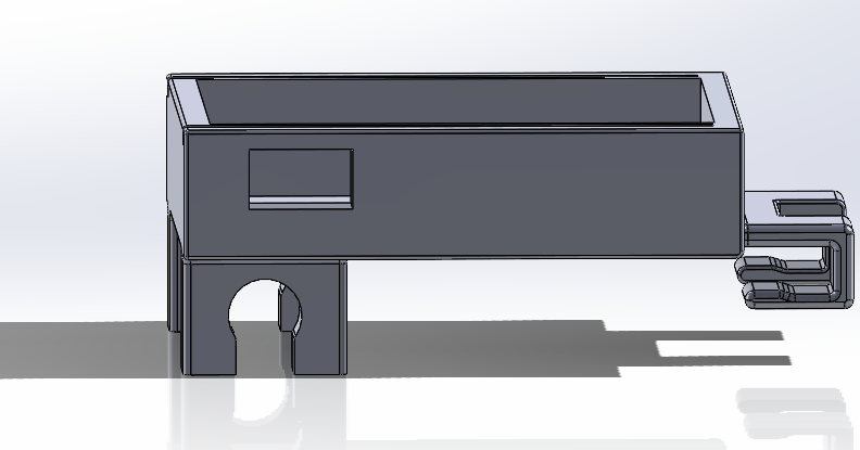
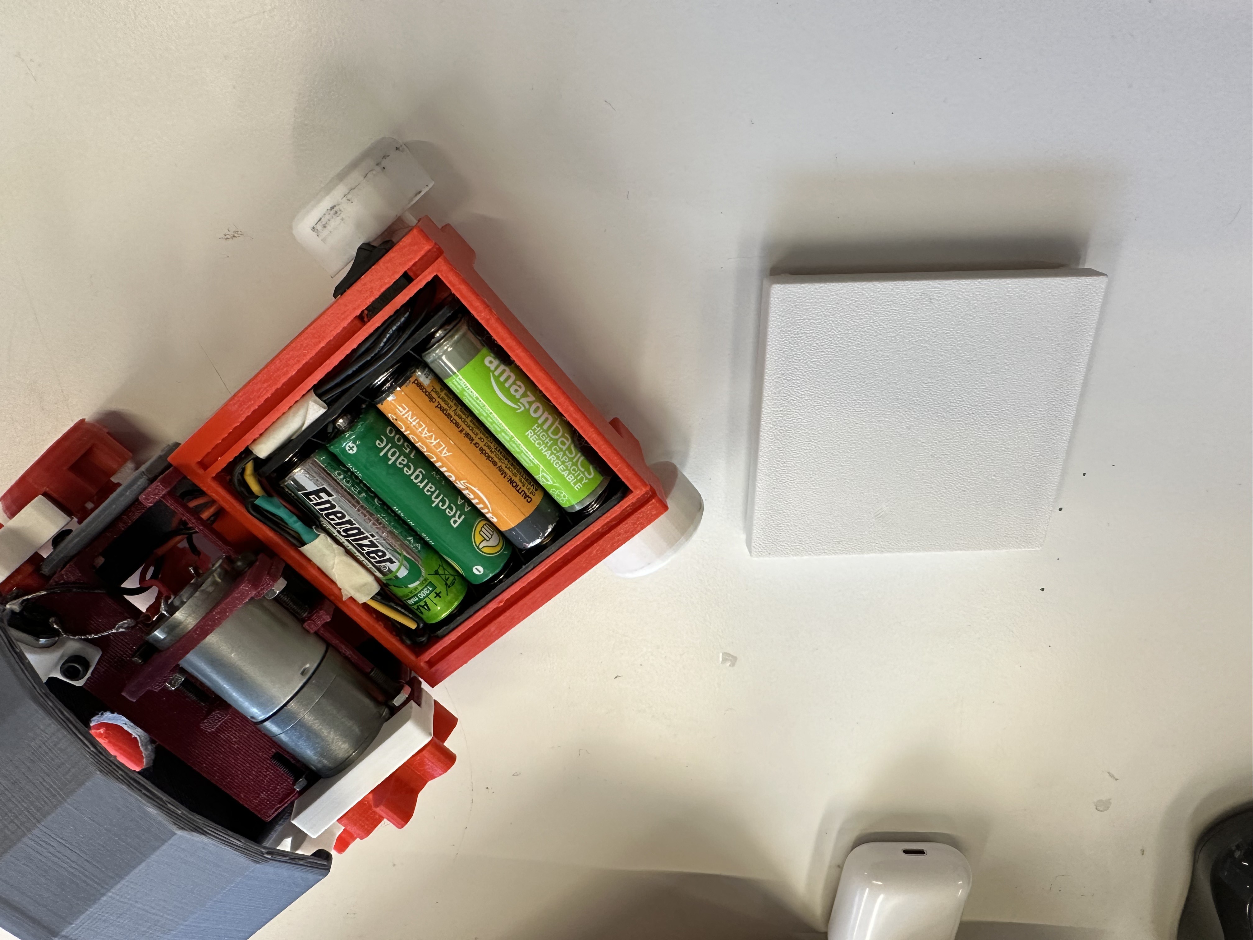
Additionally, we designed a trailer to hold the battery. We crafted a geometry that would fit and attach to the train without compromising its appearance. However, when printing the trailer, we initially did not account for the cables or the necessary tolerances for a proper fit, so we had to reprint it after making the necessary adjustments to ensure everything fit perfectly. Once redesigned, the switch and cables fit as intended. We also created a clipping mechanism to optimally attach the trailer to the train. We considered having a whole where to pass the wires through and another one for placing the switch button.![]()
Trailer for the batteries
![]()
Detail of the clip mechanism for attaching it to the rest of the train assembly
![]()
White lid for hiding the battery
![]()
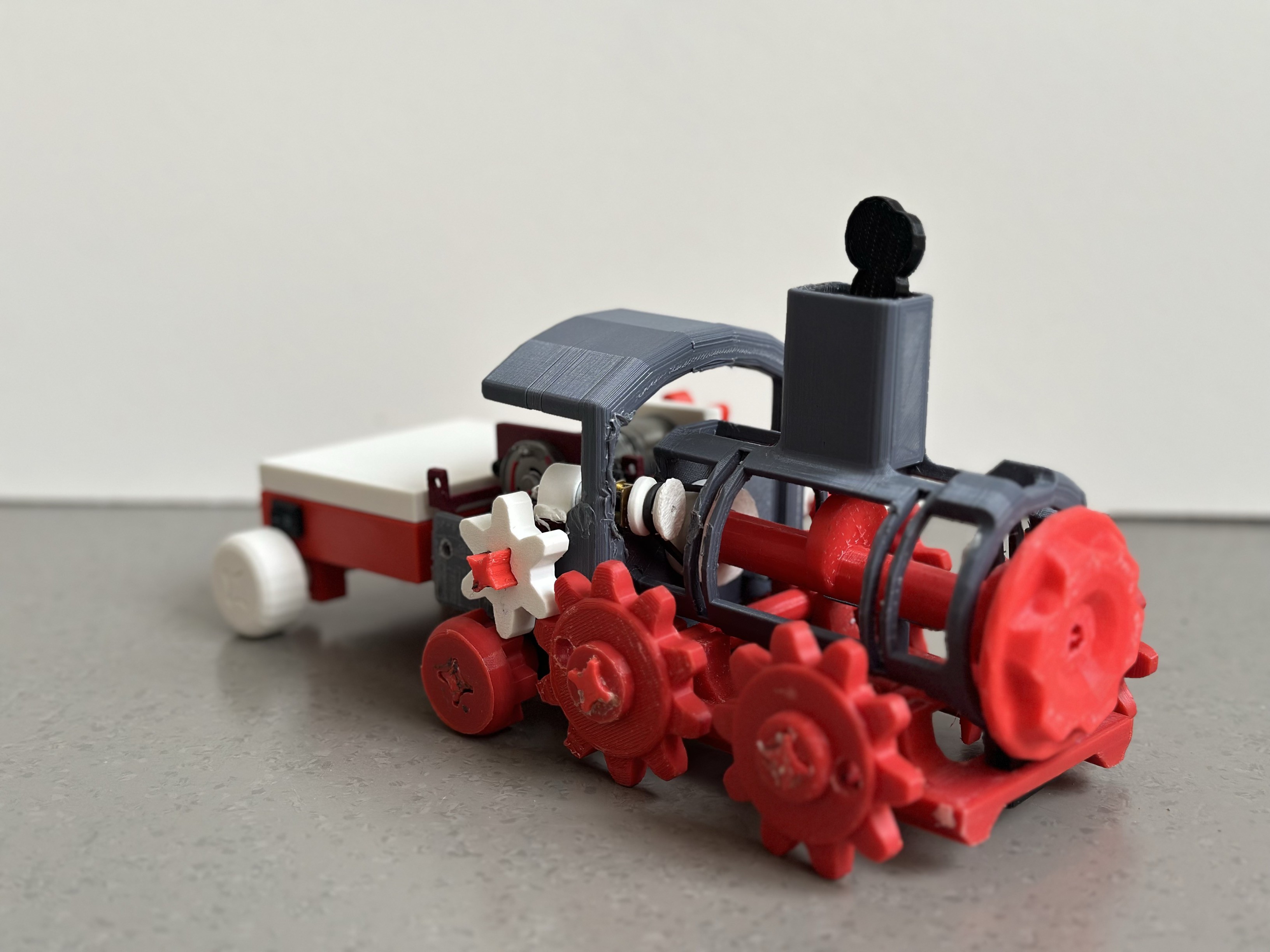
The motor support is assembled with the new piece that fixes the motor, the drive gear, and the trailer where the where the battery will be hidden
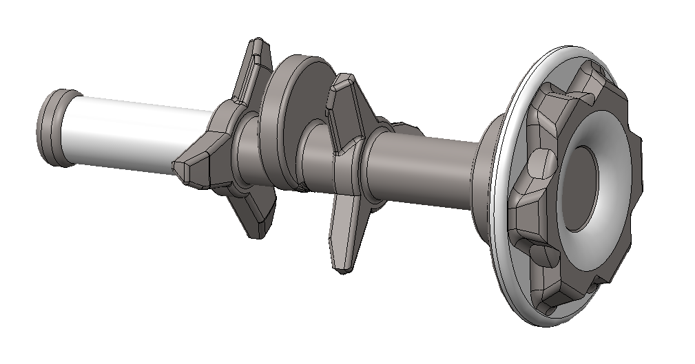
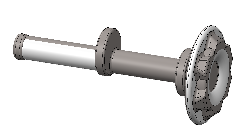
At this point, the train was operational, with the drive gear enabling movement. However, we wanted to improve so we focused on the large central axis, which initially featured blades intended to be driven by the gears. Due to a design flaw, these blades caused the train's movement to stuck. Therefore, we redesigned the axis without the blades and added two more gears (one in the tiny motor and one in the central axis) to automate the axis and display the smoke cam follower.
![]()
Central axis assembled with its respective wheels connected to the motor
These gears needed to be placed at a specific distance to accommodate a sufficiently taut rubber band, ensuring smooth rotation without slipping.
In terms of speed, we needed to consider what gear/wheel needed to be the bigger one. The central axis should have the big gear and the little gear should be fit in in the little motor. ¿Why did we assign the gears this way? Because this means that when the gear of the little motor completes one rotation, the bigger gear will not have completed one, ensuring it moves more slowly. So for the reason we will put the smaller gear connected to the motor and the bigger in the axis.
![]()
Distance between the wheels to enable movement
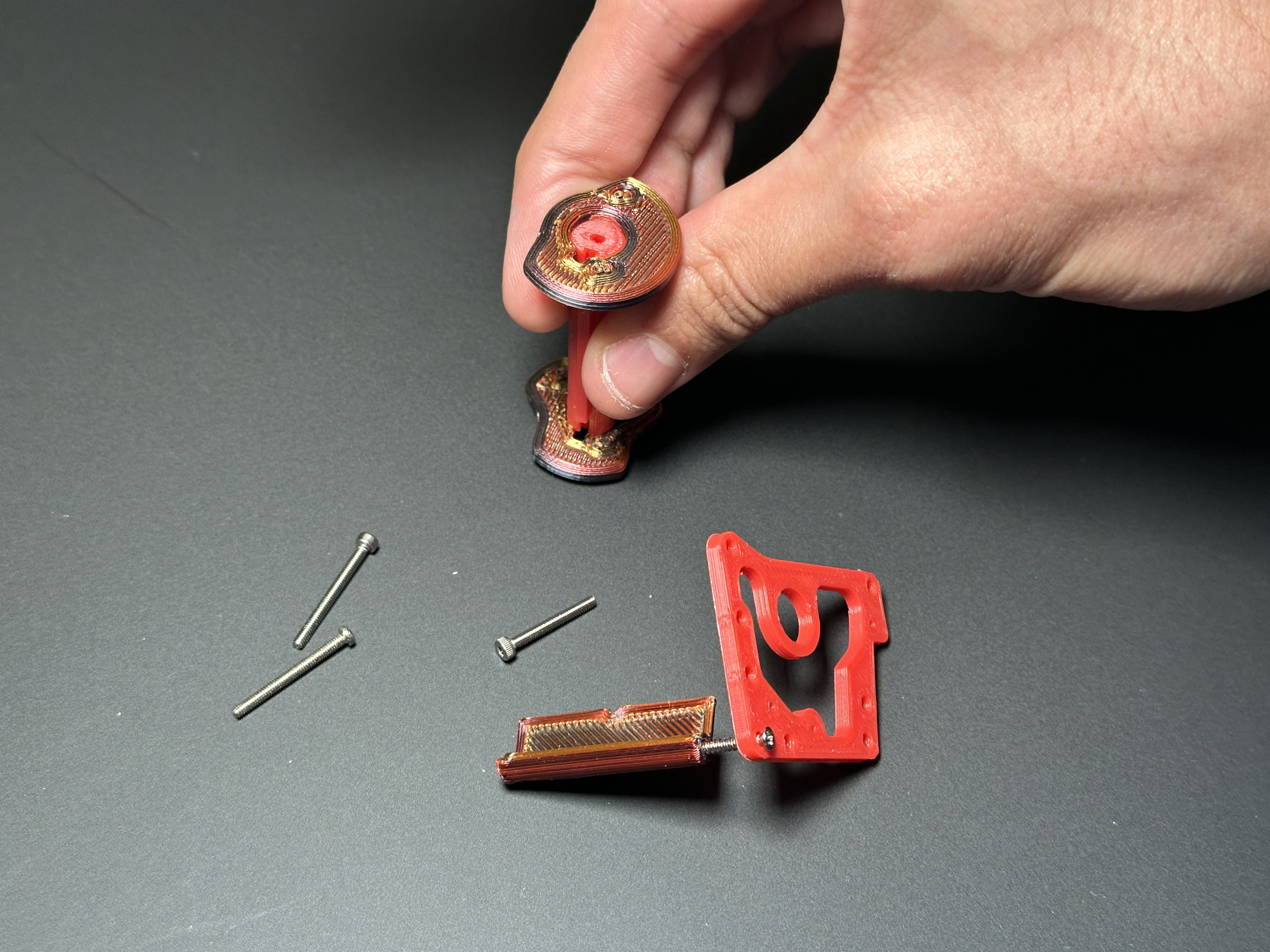
After implementing this, we overlooked the fact that we also needed to attach in some way this little motor to the big motor's support. To solve this problem, we designed one of the mounting pieces to include screws, securing the piece to the motor to prevent it from moving in any direction, thus allowing the motor to function correctly.
![]()
Piece that holds and secures the small motor
Regarding the batteries, since we have two motors but not enough space to accommodate two batteries, we decided to power both motors using a single battery. To achieve this, we connected the positive wires from both motors, soldered them together, and then soldered them to the positive terminal of the battery. Similarly, we connected the negative wires from both motors, soldered them together, and then soldered them to the negative terminal of the battery.
Finally, after all these updates in the train's CAD, we achieved a fully functional device that could move by itselft when turning power on. -
Week #8
05/21/2024 at 14:44 • 0 commentsIn today's class, we focused on refining a new component that complicated the complete smooth movement of the train. The decision to remove the gears was based on their tendency to complicate the overall movement of the train assembly. We redesigned this axle and removed some helical elements it had. These helices were supposed to make the axle rotate by colliding with the wheel axis when the wheels moved. However, after printing and testing it in real life, this mechanism didn't work quite as well as expected. Therefore, we decided to remove the helices and install another mechanism to ensure the shaft rotates properly. By redesigning the piece without the helices, we aim to achieve a smoother and more dynamic motion.
![]()
Redesigning this piece
.
Our primary task today was to sand the new printed piece meticulously. This step is crucial because any imperfections in the surface could hinder the rotational movement, leading to a less efficient operation. By sanding the piece, we aim to reduce unfinished rough surfaces and ensure that the cam follower moves smoothly within its designated path. This will contribute to a more fluid movement of the entire train mechanism, enhancing its overall performance. The improved design has a more reliable and effective operation, making the movement of the train assembly as smooth and dynamic as possible.
![]()
Redesigned axis without the helices
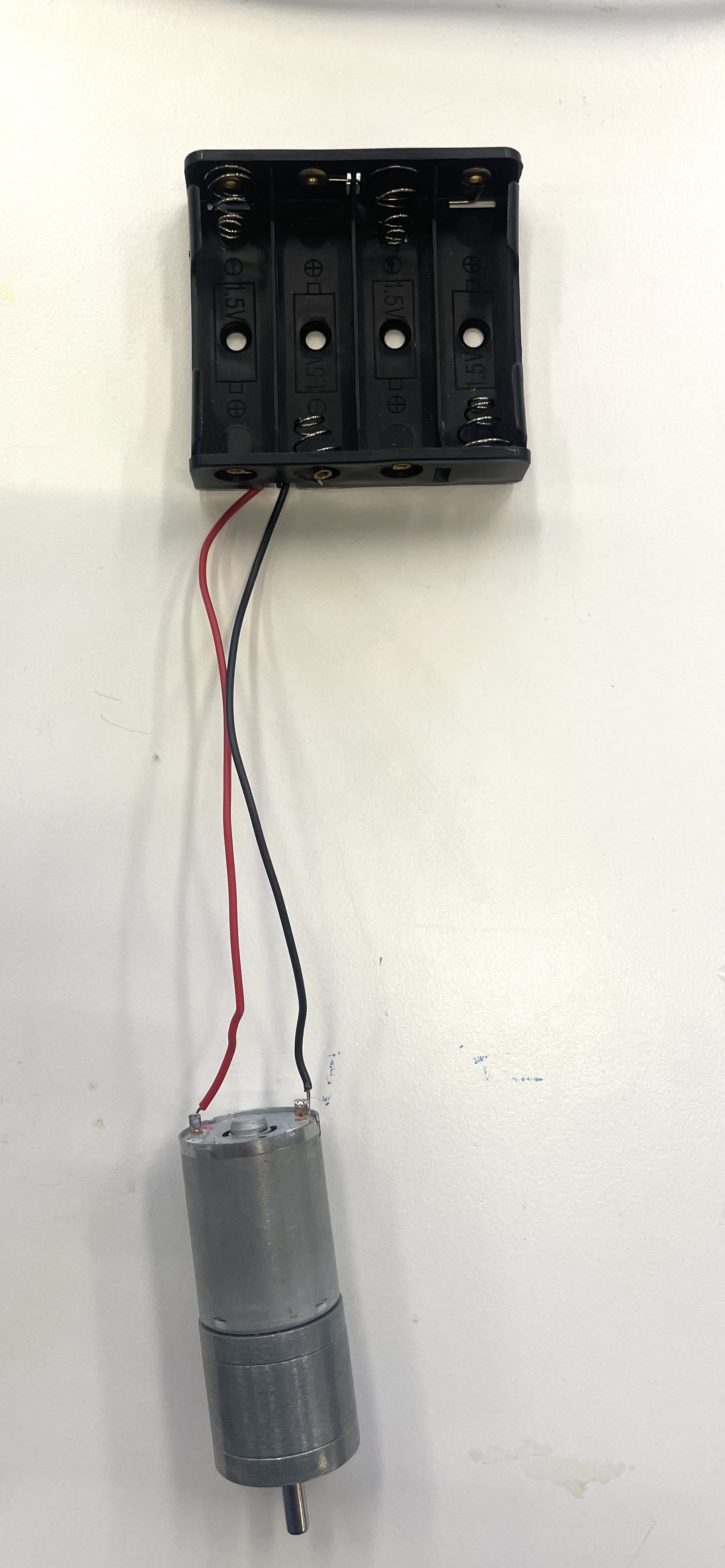
Furthermore, we successfully integrated the geared DC motor into the system by establishing a connection to the battery. This involved a meticulous solding process to connect the cables to ensure secure and reliable electrical connections. By using solding techniques with tin, we created strong bonds between the wires and the terminals, which is crucial for maintaining electrical conductivity and preventing any potential interruptions in power flow.Once the cables were securely solded, we carefully checked they were appropriately connected to positive and negative terminals of the battery before turning on the motor by connecting the batteries to the batery holder. This ensures that the motor receives the necessary electrical current to initiate and sustain its operation. By adhering to proper polarity, we ensure that the motor rotates in the desired direction, which in this case, is clockwise.
![]()
Solder motor to a 6V battery
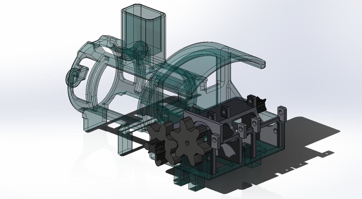
This integration of the DC motor with gears into the system marks a significant milestone in our project, as it brings us closer to achieving our desired functionality. With the motor now connected and ready for operation, we can proceed with further testing and fine-tuning to ensure optimal performance.Lastly, we designed a support to fit the motor with the new geared wheel that drives the entire train (driver geared wheel). This support includes a component that is screwed in place, ensuring the motor remains stationary and securely locked in position. For calculating the distance where to place the driver geared wheel and ensure the wheel could mesh correctly, we used the Pythagorean theorem to determine the appropriate height and distance from the gear next to it for the driving wheel to function properly.
![]()
Support to fix the motor in place
Additionally, we had to redesign the geometry of the driver geared wheel, as we are going to fit it in the motor's axle. This way, when it rotates, it will drive the other gears, facilitating the entire movement. To achieve this, we had to measure the diameter of the motor's axle to ensure it fits perfectly with the wheel, leaving just the right tolerance for a proper fit.![]()
Detail of the geared wheel with the geometry of the motor axis
The following image shows the piece that locks the motor in its position. Additionally, we have integrated a geometry into the motor support that secures one of the jn5`56axes, preventing it from moving upwards and coming off its shaft when the train is in motion. Previously, we encountered this issue with the axis, which hindered the train's proper movement.![]()
support lock for the motor
Overall, today's class was dedicated to ensuring that the new piece is perfectly prepared for its role in the train assembly, reflecting our commitment to precision and efficiency in our engineering work
-
Week #7
05/14/2024 at 16:19 • 0 commentsIn today's class, we received the 3D reprinted parts, enumerated them, and verified that were all present. Some pieces were missing, so we made a list and sent it for printing. Additionally, we removed the support (excess plastic) from some of the pieces and sanded them to ensure they were perfect.
![]()
Sanding process
We observed that the axis were thinner than required, resulting in excessive play in their movement. To address this, we applied duct tape to increase the thickness, providing more friction for a better rotation.![]()
Duct tape in the axis to increase the thickness
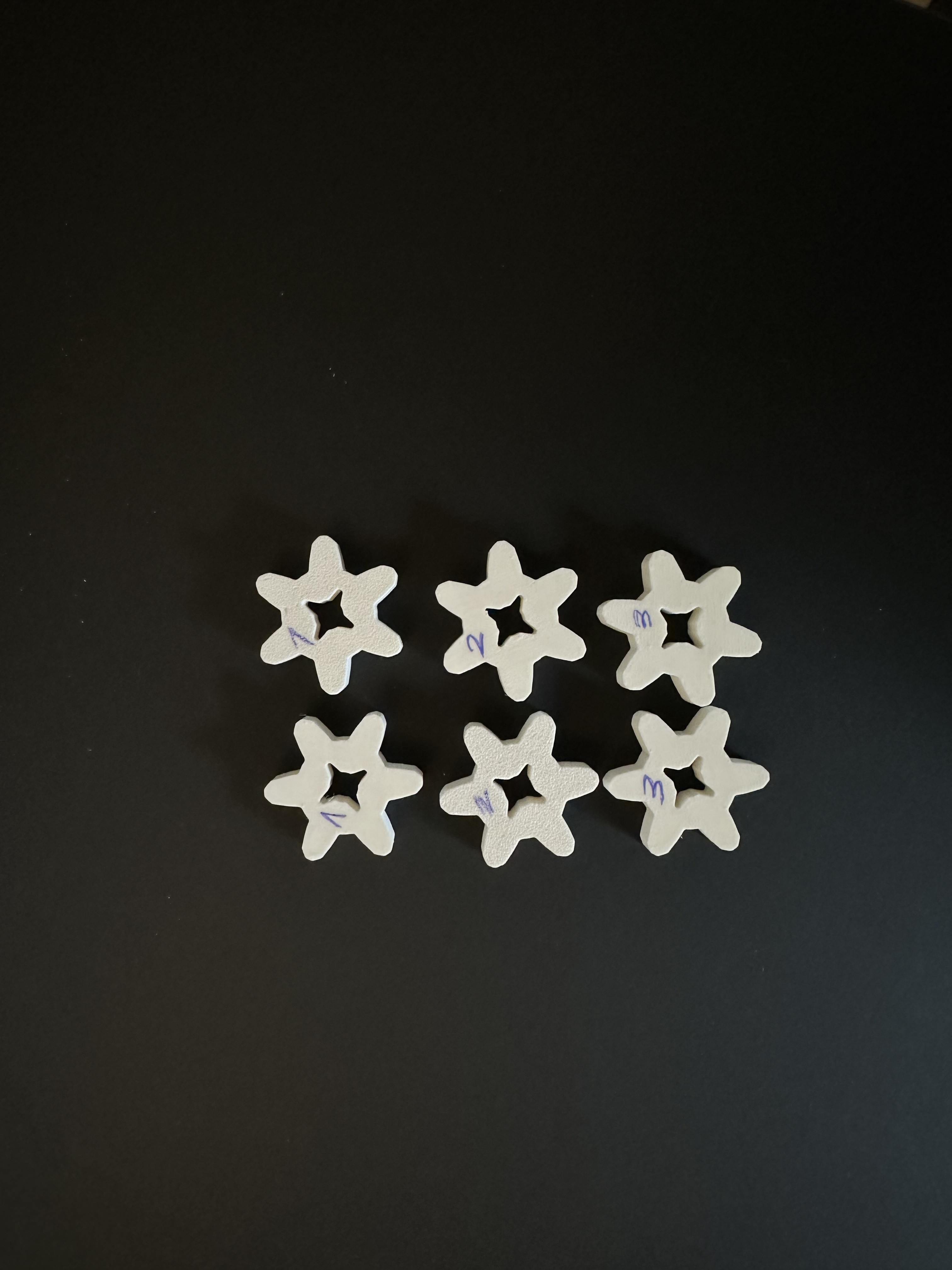
As for the gears that drive the entire mechanism, we found that their dimensions were incorrect and did not fit with the other gears. Consequently, we redesigned them with different measurements and reprinted them to determine which size works best.
![]()
Redesign of the driving gears with 3 different sizes
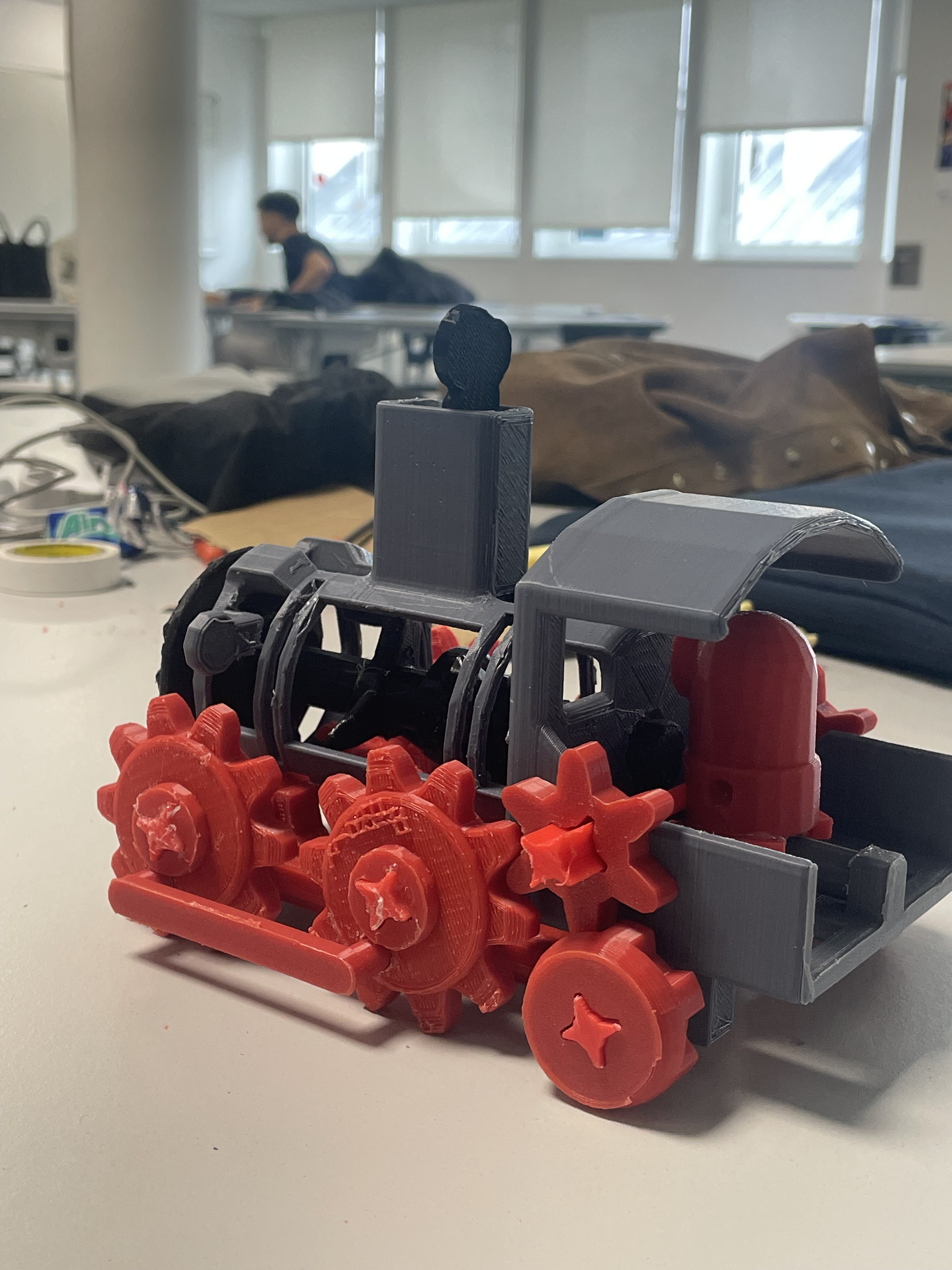
After testing the entire mechanism, we concluded that to improve the train in the future, we should choose a different material for the axis, as the plastic ones do not rotate perfectly. Moreover, since we didn't plan where to put the motor at first, we are going to design a support for the motor and battery, which will be placed at the back of the train. Since the back is the only room we have where to place the electronics and in order to have a good balance of the train whenever it is actioned, this means we will have to remove the minion behind in order to leave this room available in the train for the electronics. For future projects, we would suggest not doing inverse engineering (as we did now) but to plan every detail first before printing.![]()
Quick look at the assembled train
-
Week #6
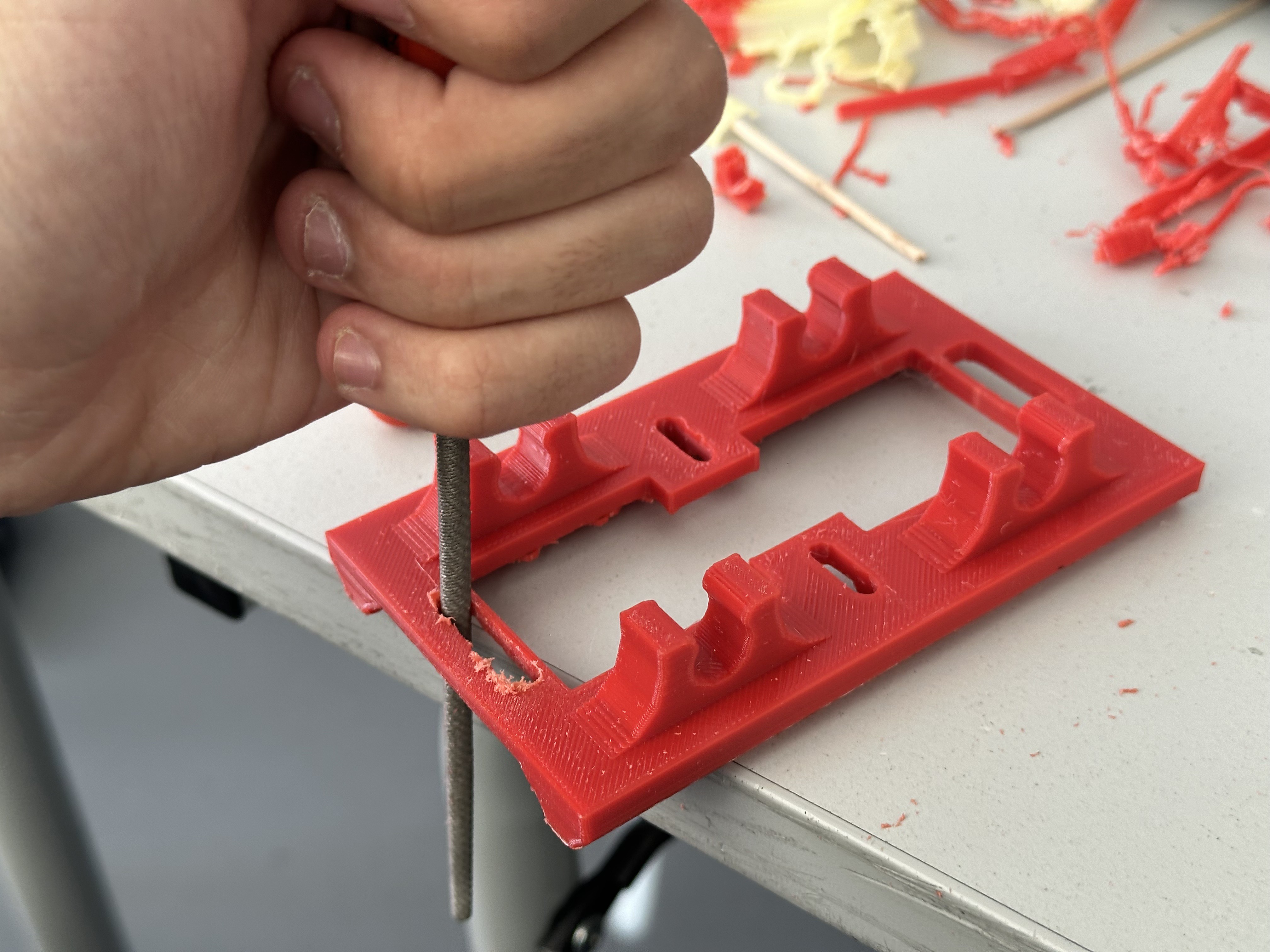
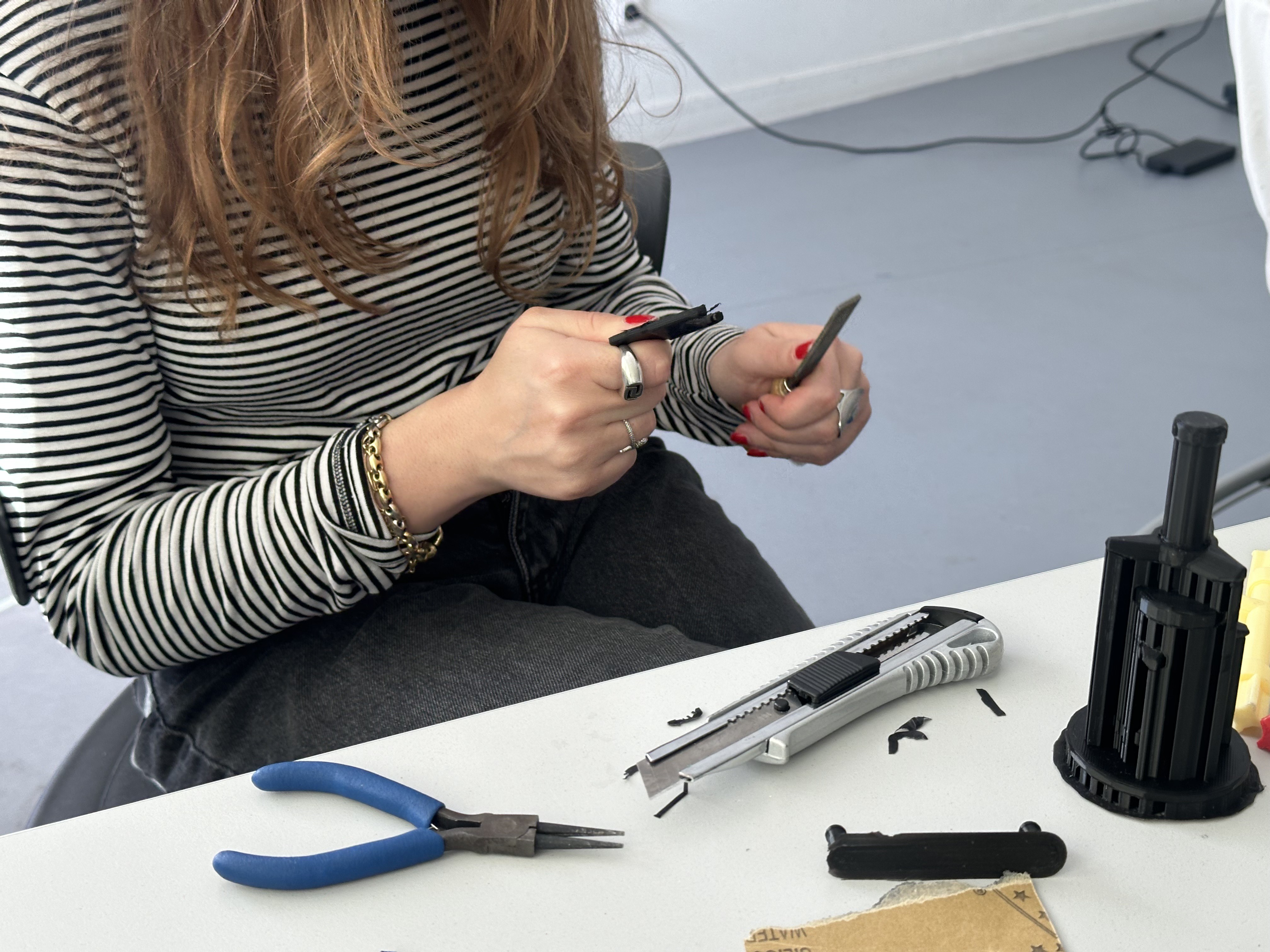
05/07/2024 at 15:21 • 0 commentsDuring today's class, we focused on perfecting the 3D pieces to ensure they fit well together. Our method involved using pliers and sandpaper to meticulously refine each piece while checking the 3d models with Solidworks to ensure how the pieces have to be.
![]()
![]()
Sanding process
After completing the sanding process for all components, we double-checked their fit and noticed that the tolerance levels for the wheels and axles weren't quite adequate. We redesigned the axis in Solidworks and print them again so that they fit.
![]()
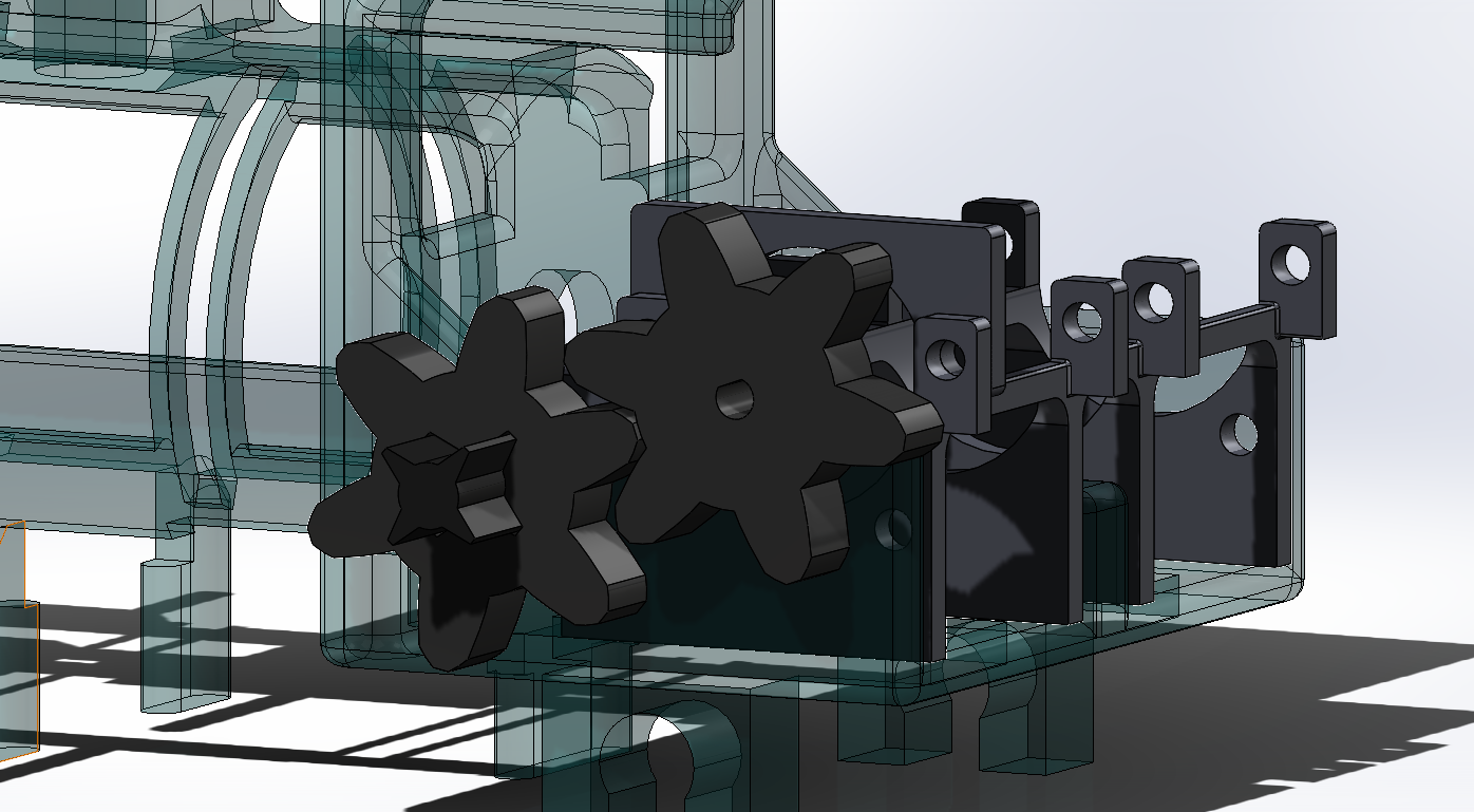
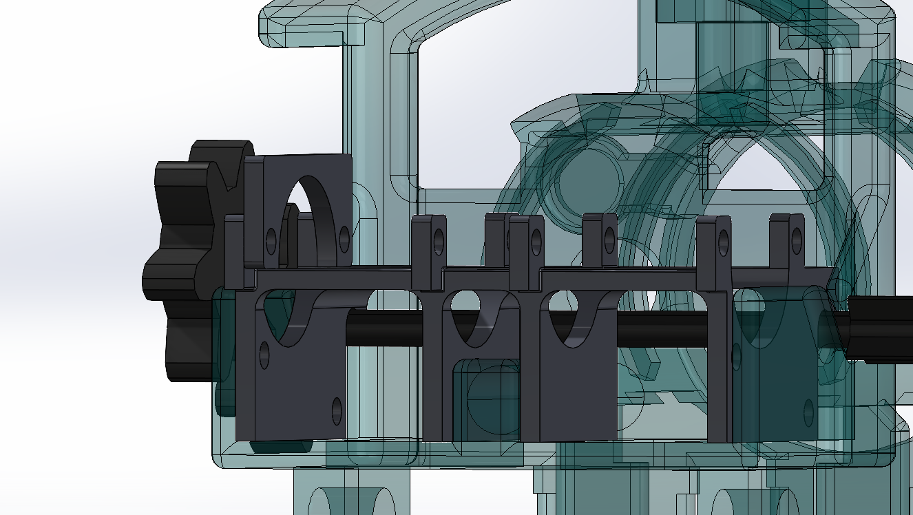
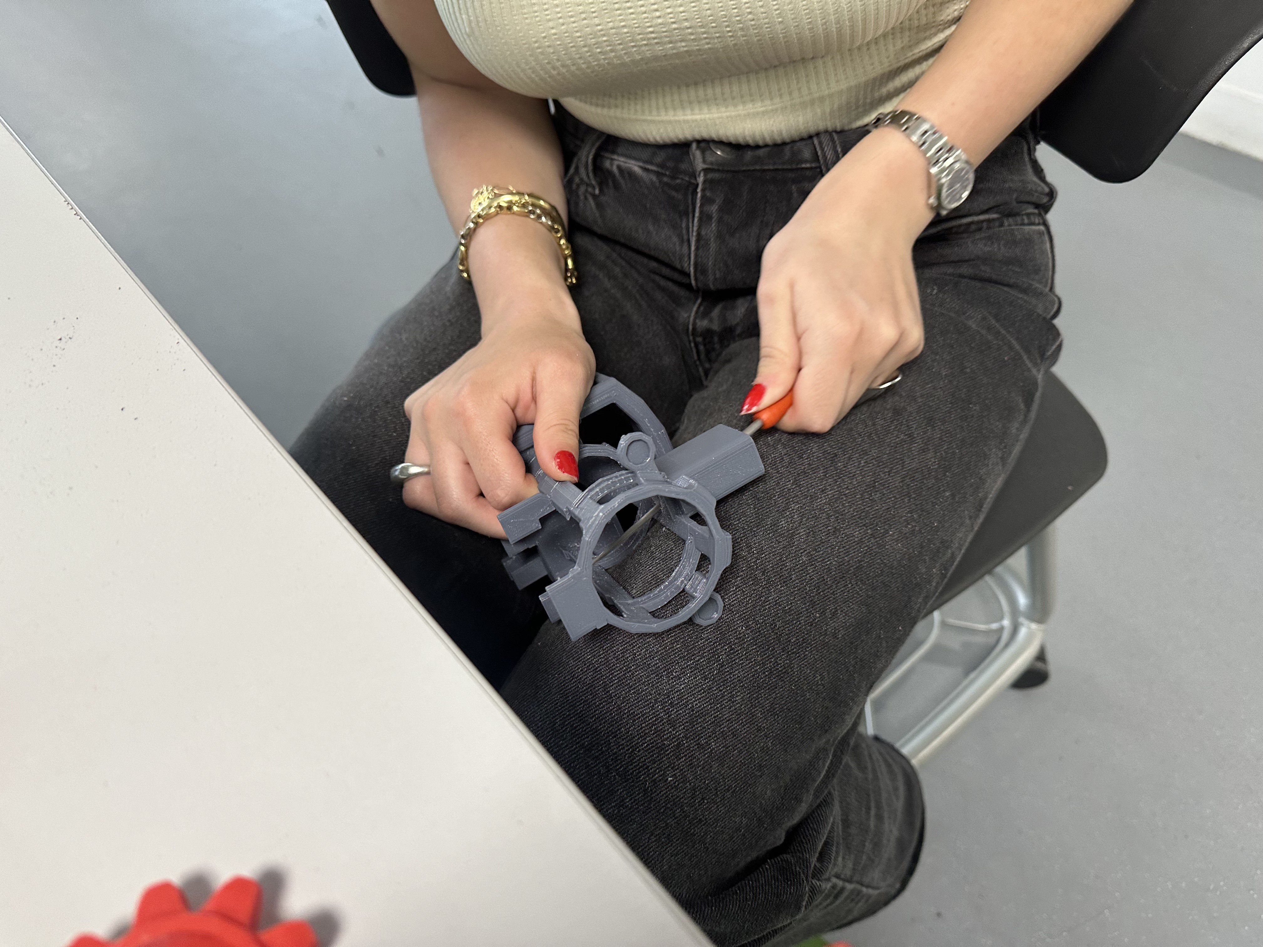
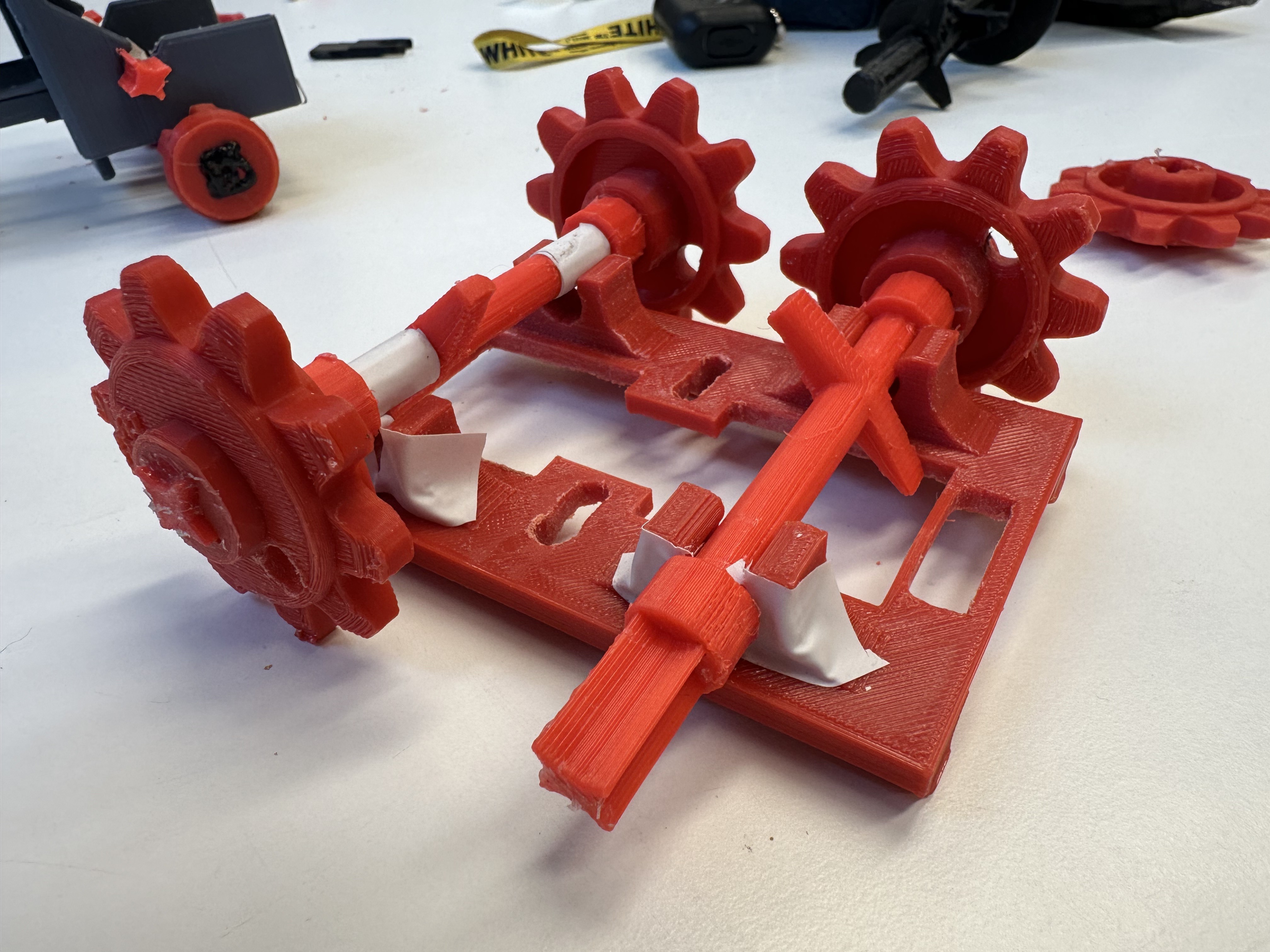
![]() Meticulously measuring the actual pieces for redesigning the parts with the proper tolerances
Meticulously measuring the actual pieces for redesigning the parts with the proper tolerances -
Week #5
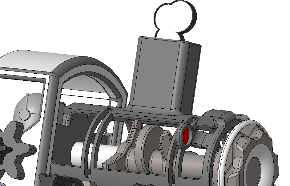
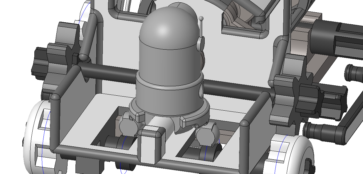
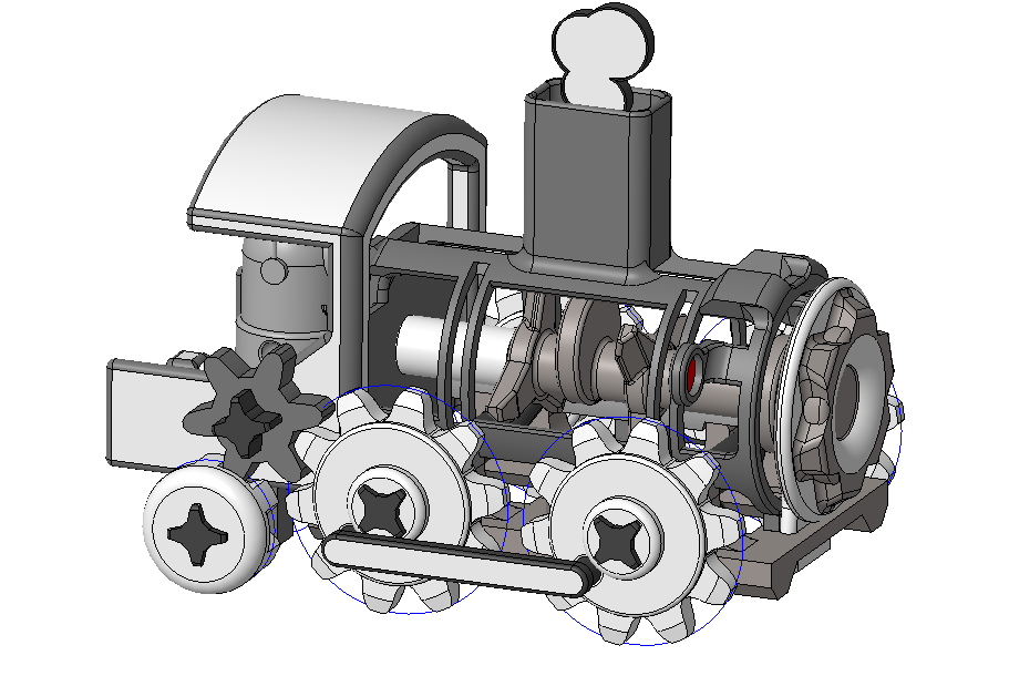
04/30/2024 at 17:06 • 0 commentsIn today's class, we focused on finding a new solution that integrates gear mechanisms and as well cam followers, following our previous research and study into this type of message display. Our goal is to demonstrate movement and make it realistic, so by using gears and designing the cam followers of train we will begin our work. In this case, we will try to simulate the smoke effect a real train would have by integrating cam-followers not only here but as well in the minion located in the back of the train. To achieve this, we downloaded a train, ensuring this could be ready for printing. Following this, we proceeded to design the two cam-followers mentioned above and to the assembly of the train as a whole.
![]()
Detail of the smoke cam
![]()
Detail of the minion cam
For assembling all parts together, we utilized the CREO 10 Parametric tool, which offers robust capabilities for assembling mechanical systems. This software allows us to visualize and simulate the movement of gears and cam followers in a virtual environment. By doing so, we can observe and refine the mechanical interactions before proceeding to the physical printing stage. This step is crucial as it ensures that all components will work seamlessly together once assembled.![]()
Train assembly in CREO PTC
The ability to simulate motion on screen provides us with a valuable preview of the final product, enabling us to make necessary adjustments and corrections. This reduces the likelihood of errors and ensures that the printed parts will function as intended. By using CREO 10 Parametric, we can confidently design complex mechanisms and ensure their proper operation, enhancing the overall realism and functionality of our steam train project. From now on, we will embark on this new direction, preparing parts for printing and working towards creating a final functional prototype.
-
Week #4
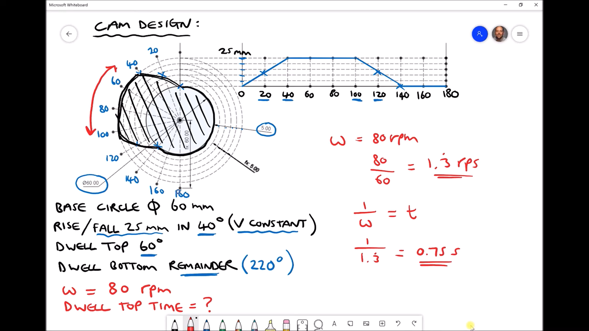
04/09/2024 at 18:25 • 0 commentsDuring this week's session, we continued our exploration on how to design a cam. To achieve this, we searched for YouTube videos to enhance our understanding. Specifically, the video attached below has proven immensely helpful, as it provided insights into selecting the appropriate RPM (revolutions per minute) for our project, as well as delving into technical concepts such as dwell. Dwell refers to "a slight regular pause in the motion of a machine." Furthermore, this video serves as a reference for potential calculations throughout the project development process, such as determining the duration of each cycle the cam will dwell in a certain position given a specific RPM (where rps = rpm/60 seconds), or calculating the time taken to complete one revolution (using the inverse of rotational velocity formula t = 1/w).
![]()
*Youtube video: Cam Design to Achieve a Specified Follower Motion. Link: Cam Design to Achieve a Specified Follower Motion (youtube.com)
Simultaneously, in this session, we endeavored to assemble the set of components required to build the clock. However, due to the precise millimetric design of these pieces, either due to their small size or issues stemming from 3D printing, this process presented challenges. As we assembled the clock, we noticed that the pieces lacked the necessary tolerances for easy fitting and assembly without compromising their integrity.
![]()
*Challenges when assembling the plastic parts.
Consequently, we made the decision to redirect our final product. It is important to acknowledge that the design process is iterative rather than linear; setbacks are part of the journey towards progress. Additionally, we identified that the fabrication of our initial clock prototype required overly complex electronic components. By simplifying our design process and replacing unnecessary components with more suitable alternatives, such as motors, we aim to streamline our workflow. As engineers, our mission is to seek solutions to the problems we encounter and provide optimal and efficient outcomes.
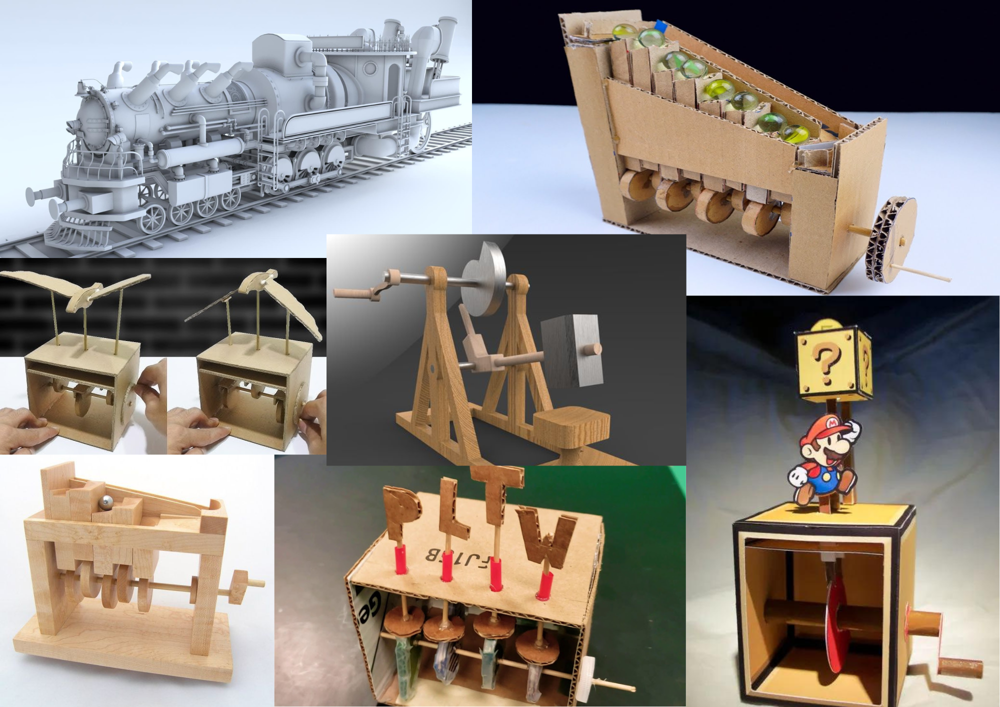
Moving forward, we are exploring alternative paths for our project. Below is a mood board featuring various product ideas that align with our project requirements.
![]()
*Moodboard of new ideas using cam, cam followers and gears.
We remain committed to the success of our project and welcome any insights or suggestions that may contribute to its advancement.
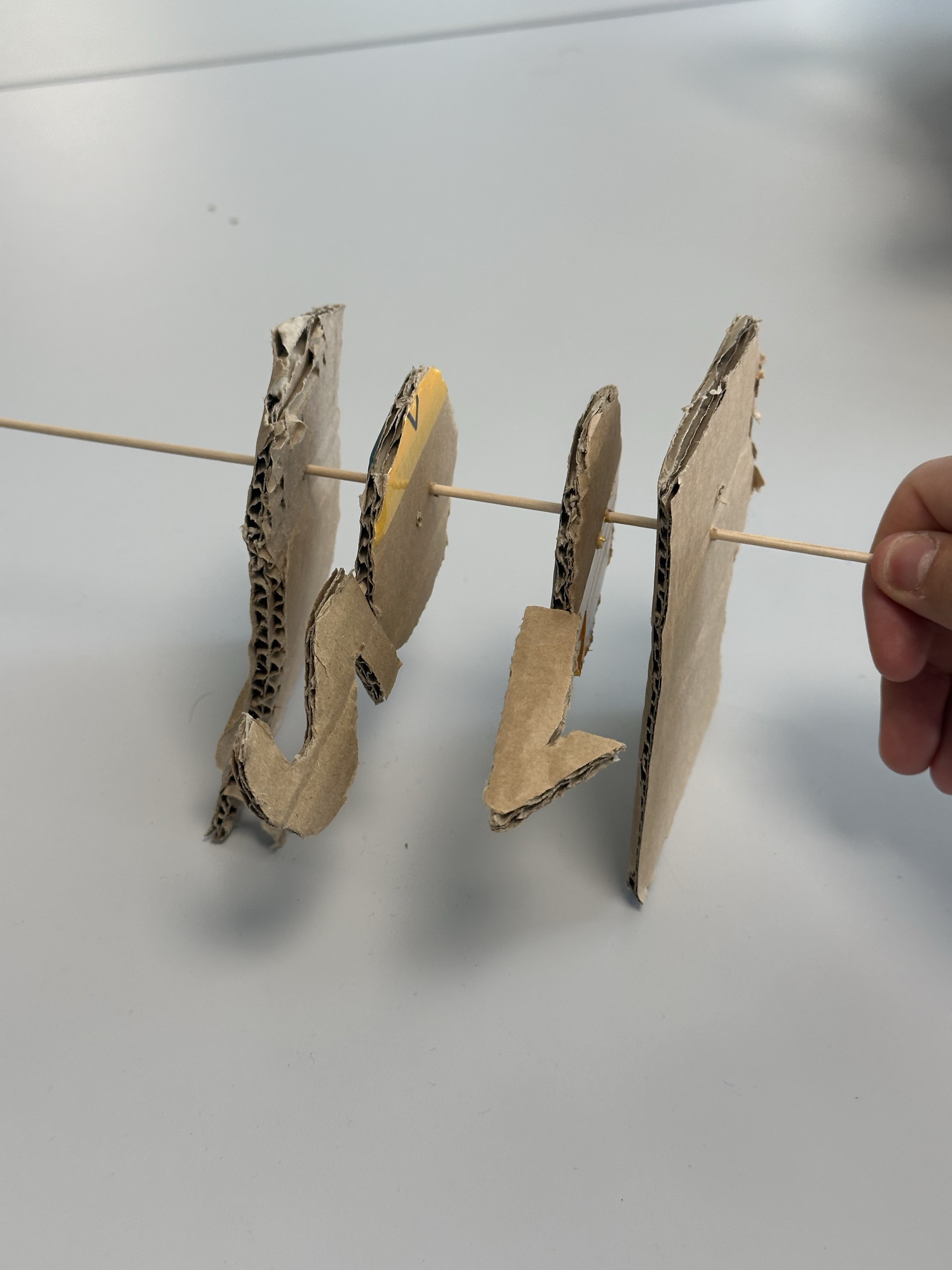
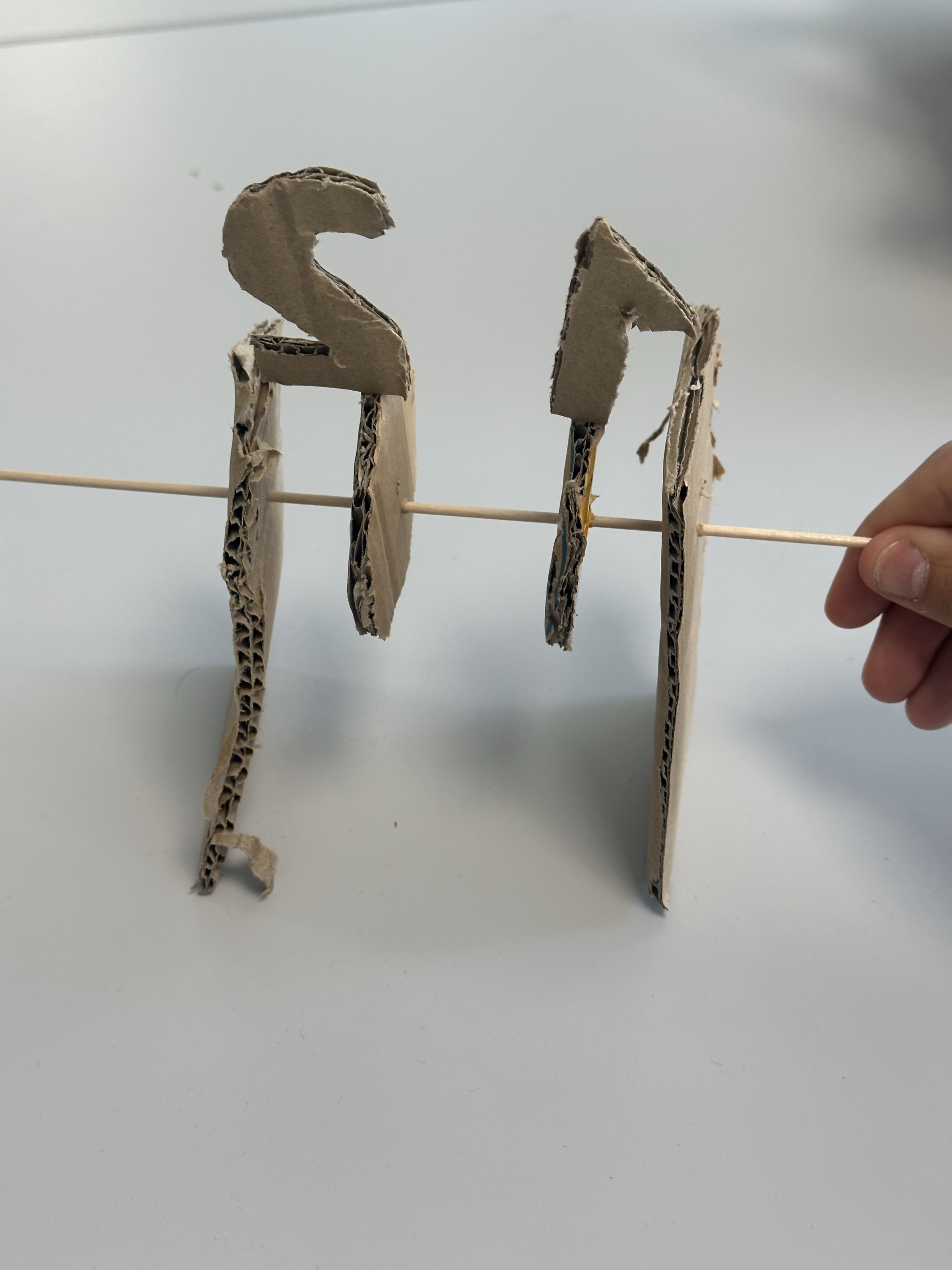
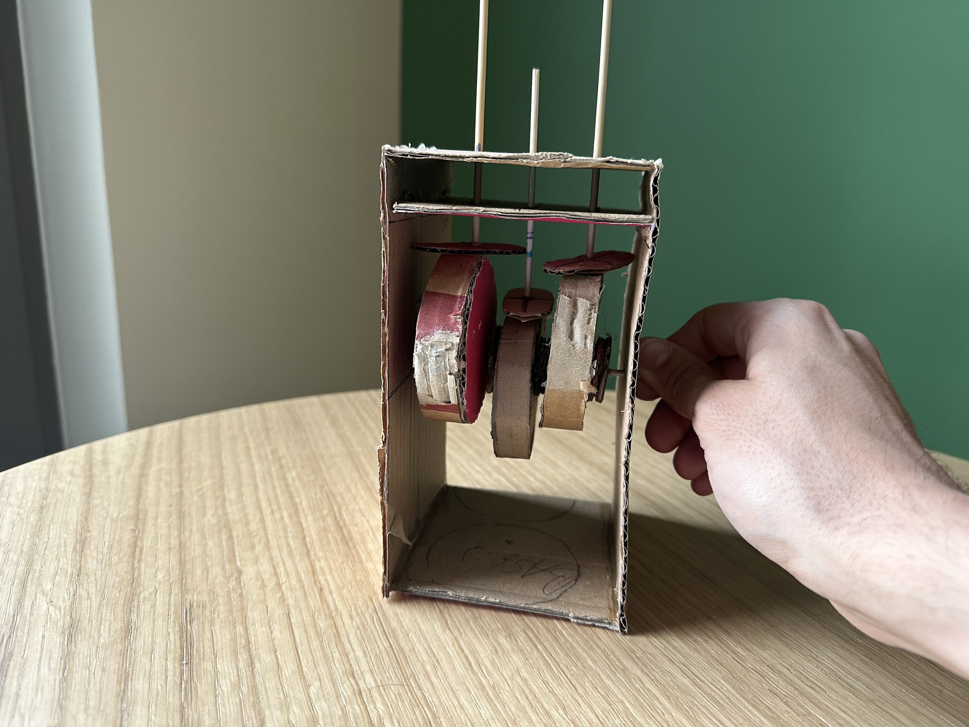
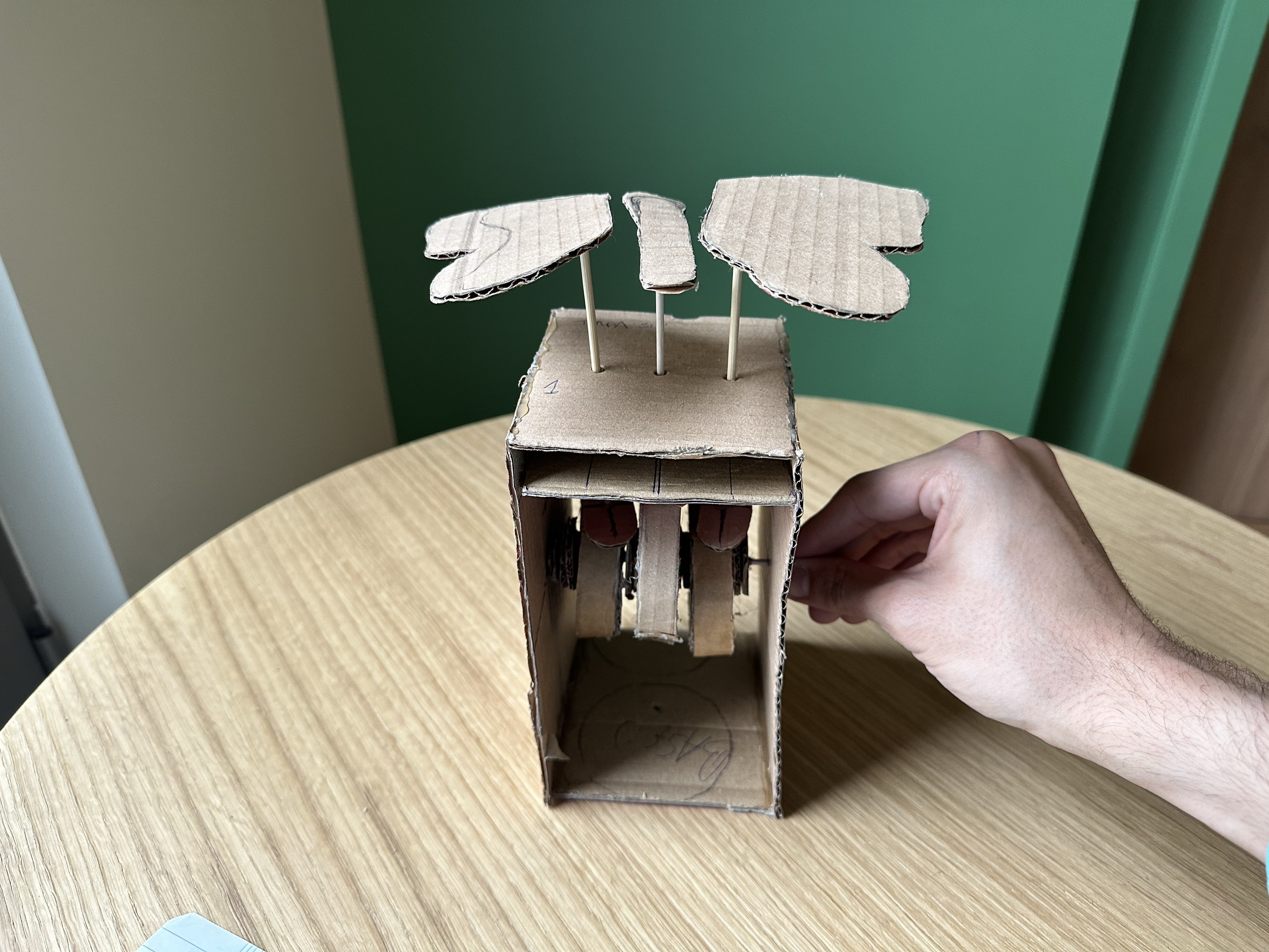
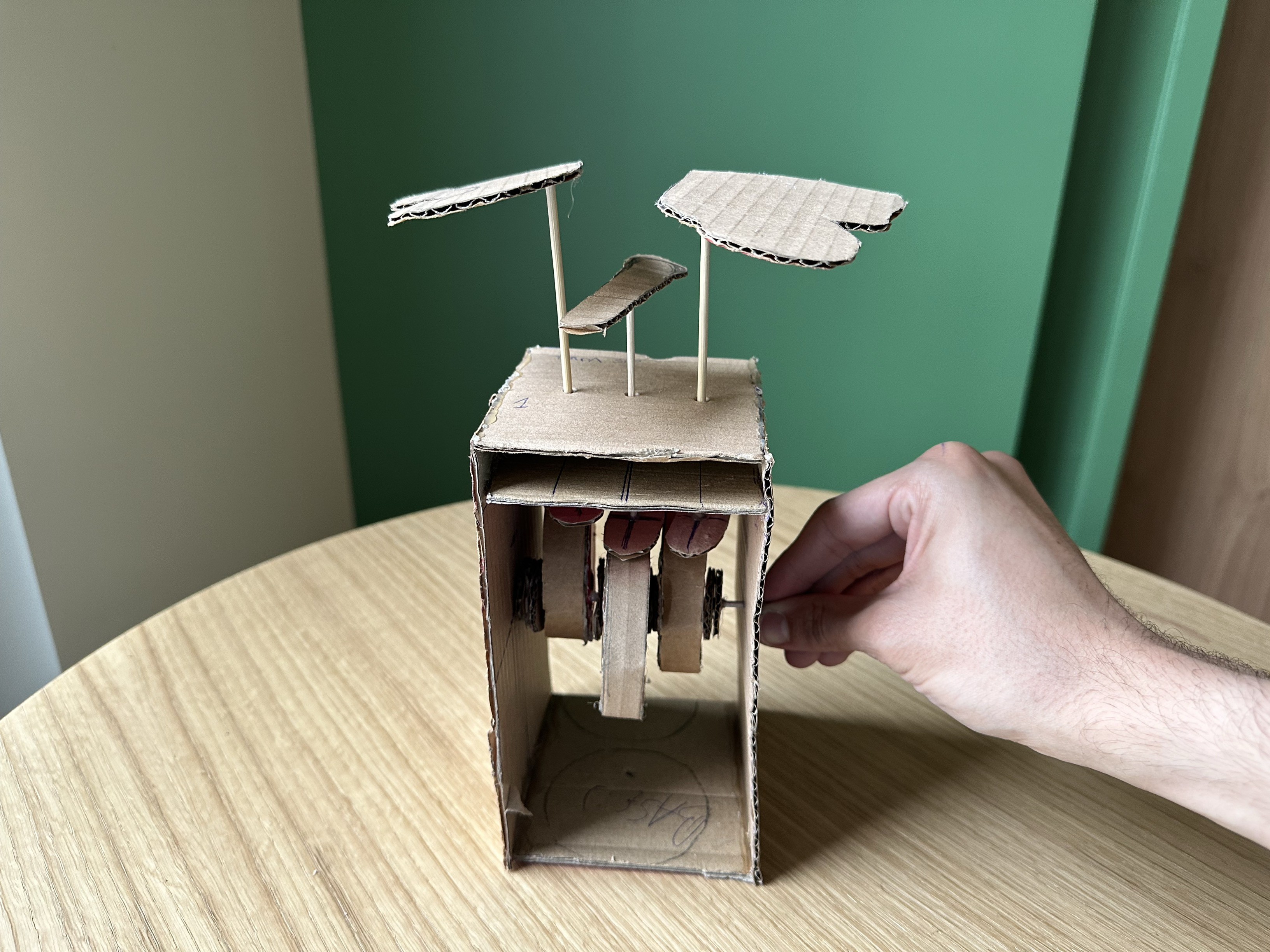
Additionally, we carried out the Minimum Viable Product (MVP) of our project. To achieve this, we developed a new prototype in cardboard to put into practice what we learnt about t cams and how the mechanism operates. Specifically, we focused on simulating the movement of a butterfly.
While creating the cardboard prototype, we encountered several complications. However, these challenges provided us with insights, particularly regarding the necessity of increasing the distance between the cams. Furthermore, a problem we had is that the sticks connected to the wings and the body of the butterfly rotate instead of remaining stationary while only executing the movement of going up and down. We will address this issue in our next session.
![]()
![]() *Trying out how cams work are working before attaching the animal we want to move.
*Trying out how cams work are working before attaching the animal we want to move.![]()
![]()
* Proving that the wings move according to the movement of the cams
-
Week #3
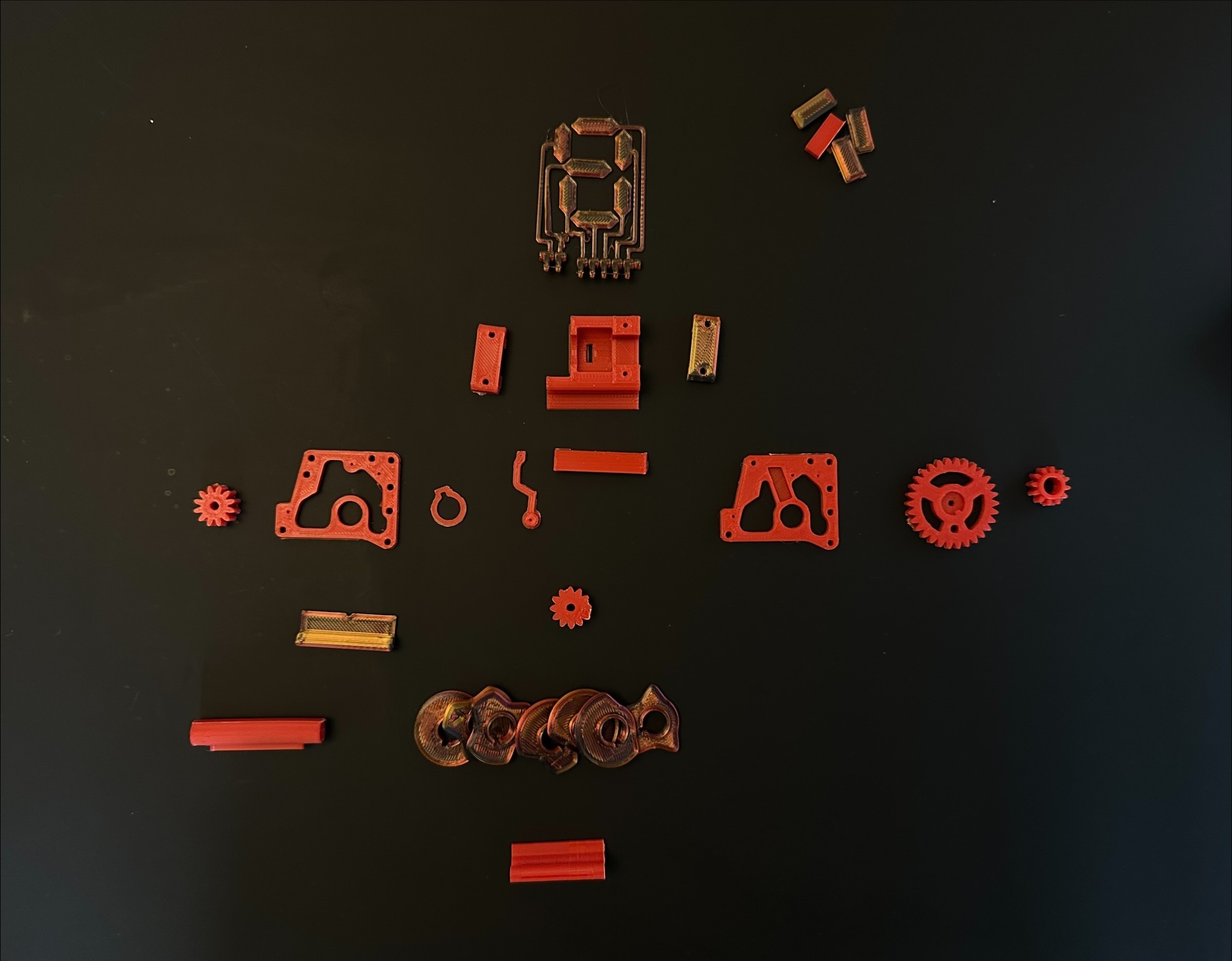
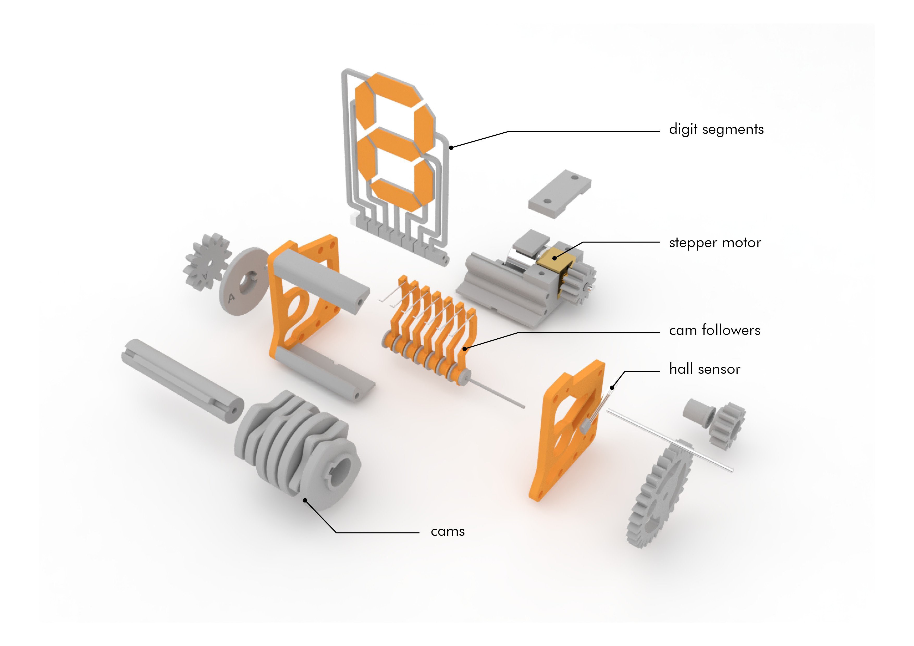
04/06/2024 at 11:44 • 0 commentsIn this session, we ensured that all the necessary parts were printed for the proper assembly of the watch and arranged them in the correct order as depicted in the image below. Furthermore, we made a study of how they will be assembled and the complex mechanism that the cam followers execute in order to allow the movement of the digits.
![]()
*Image of the inventory of pieces and exploding of how they would be assembled
Furthermore, during this session, we also delved into the intricacies of designing cams. Below is a photo accompanied by an explanation. As depicted, a cam follower comprises an initial circumference to which various curves are added. These curves facilitate different movements to ensure that the intended message is not constant over time but rather displays different letters/numbers along the path. In a linear perspective, starting from 1, if we desire a constant display for a few seconds, we assign a straight line from 1-3. This means that the cam's circumference maintains a constant geometry during this time interval. Subsequently, from 3-5, we introduce a peak. This action prompts the cam to push the cam-follower, resulting in a change in the displayed message on the clock. This sequence continues accordingly. It is crucial to emphasize that, to ensure proper cam functionality, these peaks should have zero derivatives. In other words, between a straight line and a peak, a curve should be incorporated to prevent the cam mechanism from jamming due to a potential collision in that area.
![]() Explanatory drawing
Explanatory drawing -
Week #1 & Week #2
03/26/2024 at 15:04 • 0 comments#Week1
Our project is all about the intricate task of designing a complex kinetic device. From analog kinetic sculptures to vehicle drive trains, the spectrum of possibilities is vast, promising a challenging yet rewarding journey ahead. Our primary objective is to harness the principles of mechanical engineering to construct a device that not only functions seamlessly but also captivates with its aesthetic appeal.
After brainstorming various ideas using mechanisms like gears, cams, and cam followers, firstly we settled on the concept of designing a mechanical-geared clock. Understanding the complexity involved, we took a deep dive into the workings of this clock's mechanisms.
To better understand how these gears and cams worked, we created a simple cardboard prototype of the clock. This gave us valuable insights into how the clock's mechanism functions.
We also spent time searching for design inspiration to ensure our clock stands out as both functional and visually striking. Through research and creative exploration, we aimed to give our design a unique and captivating aesthetic.
Looking ahead, our focus remains on refining our understanding of the clock's mechanism and bringing our creative vision to life. As we continue with this project, we are committed to pushing the boundaries of innovation and craftsmanship.
Attached is a visual representation of our progress for reference.
![]()
![]()
*Our first rapid-prototyping resulting clock
![]()
*Our inspiration geared-clock
#Week2
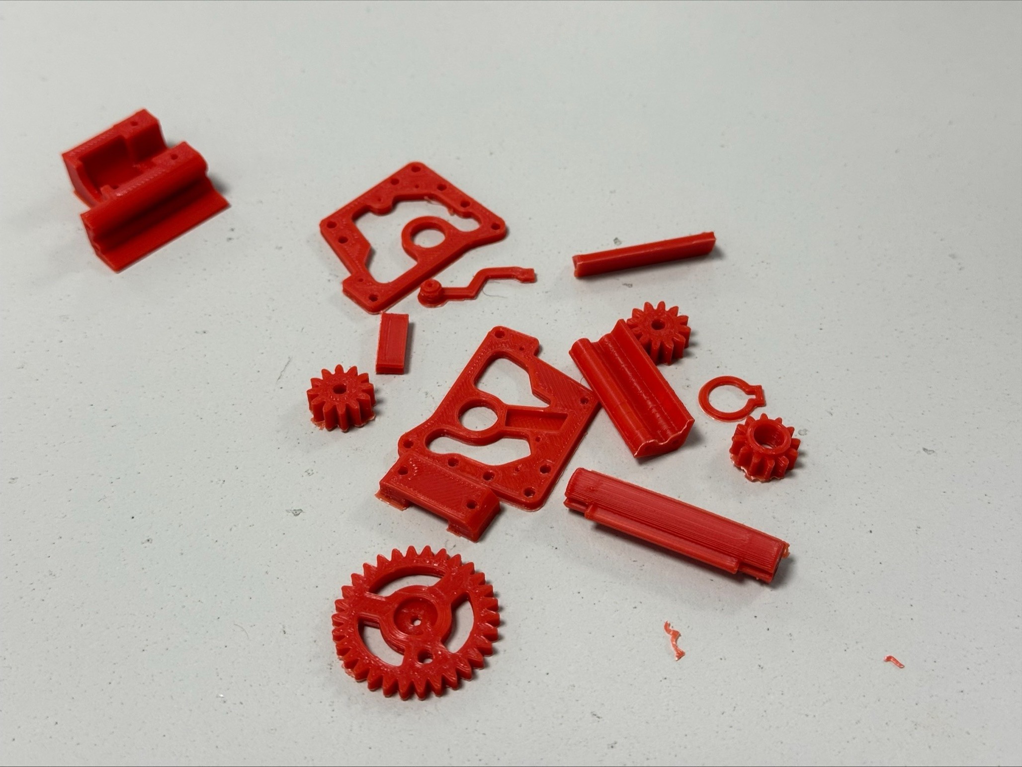
During this session, we focused on searching for 3D CAD models and printing the necessary parts to manufacture and test the operation and mechanism of a clock composed of gears.
Once the parts were printed, as they seemed to have been manufactured with the smallest 3D printable size possible, we evaluated and ensured that they had an appropriate size or scale for comfortable working. To avoid wasting material, we printed only a few pieces to verify the aforementioned.
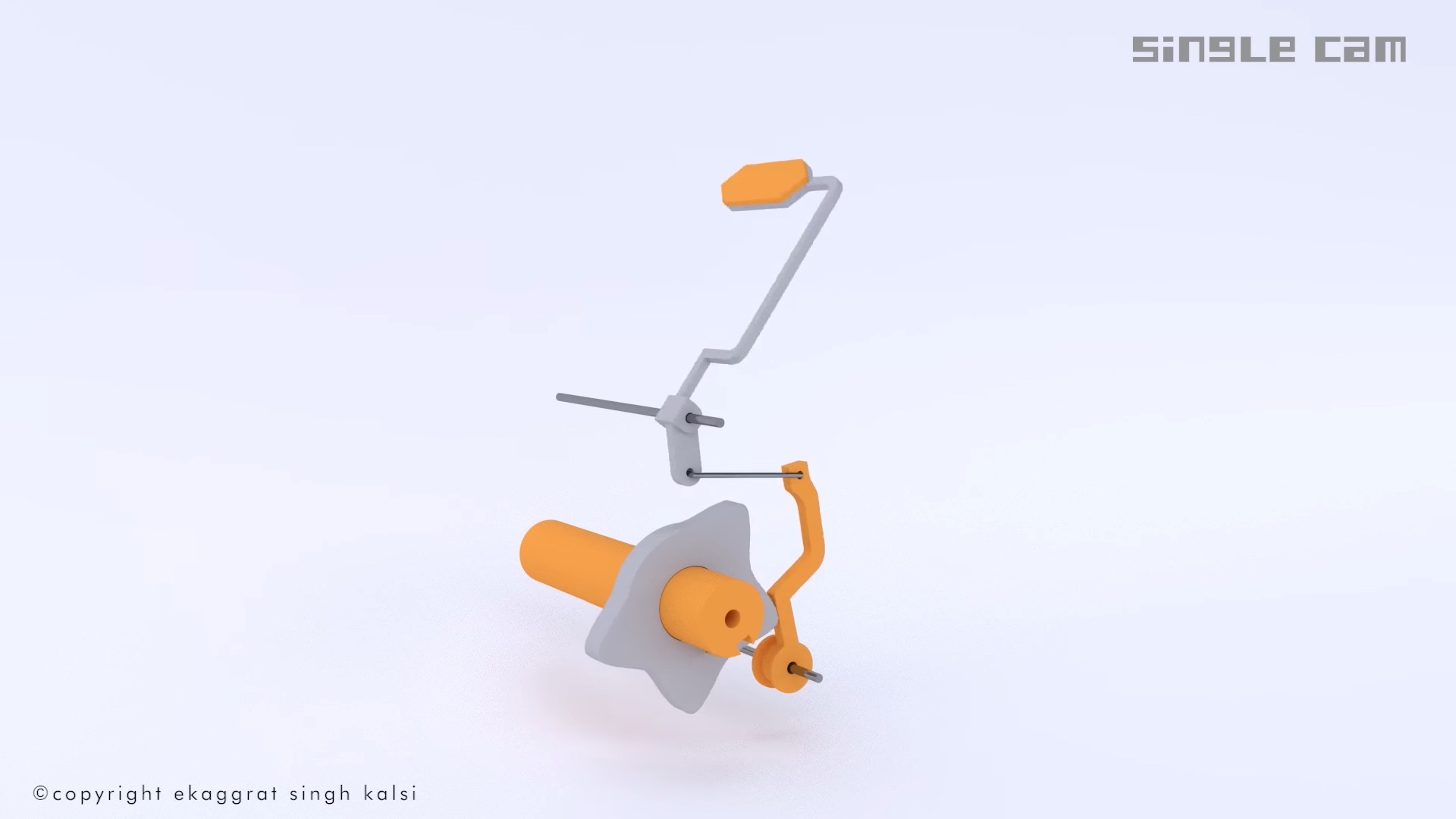
Furthermore, we dedicated this session to understanding the geometry required for a cam to push a cam-follower and how this assembly can display a message to the user, in this case, the time. We attach a photo of a video we found on the internet, which proved to be very useful and excellent for understanding how cams work.
![]()
*First parts printed
![]()
![]()
*Understanding of how a cam works simultaneously pushing a cam-follower to display a message

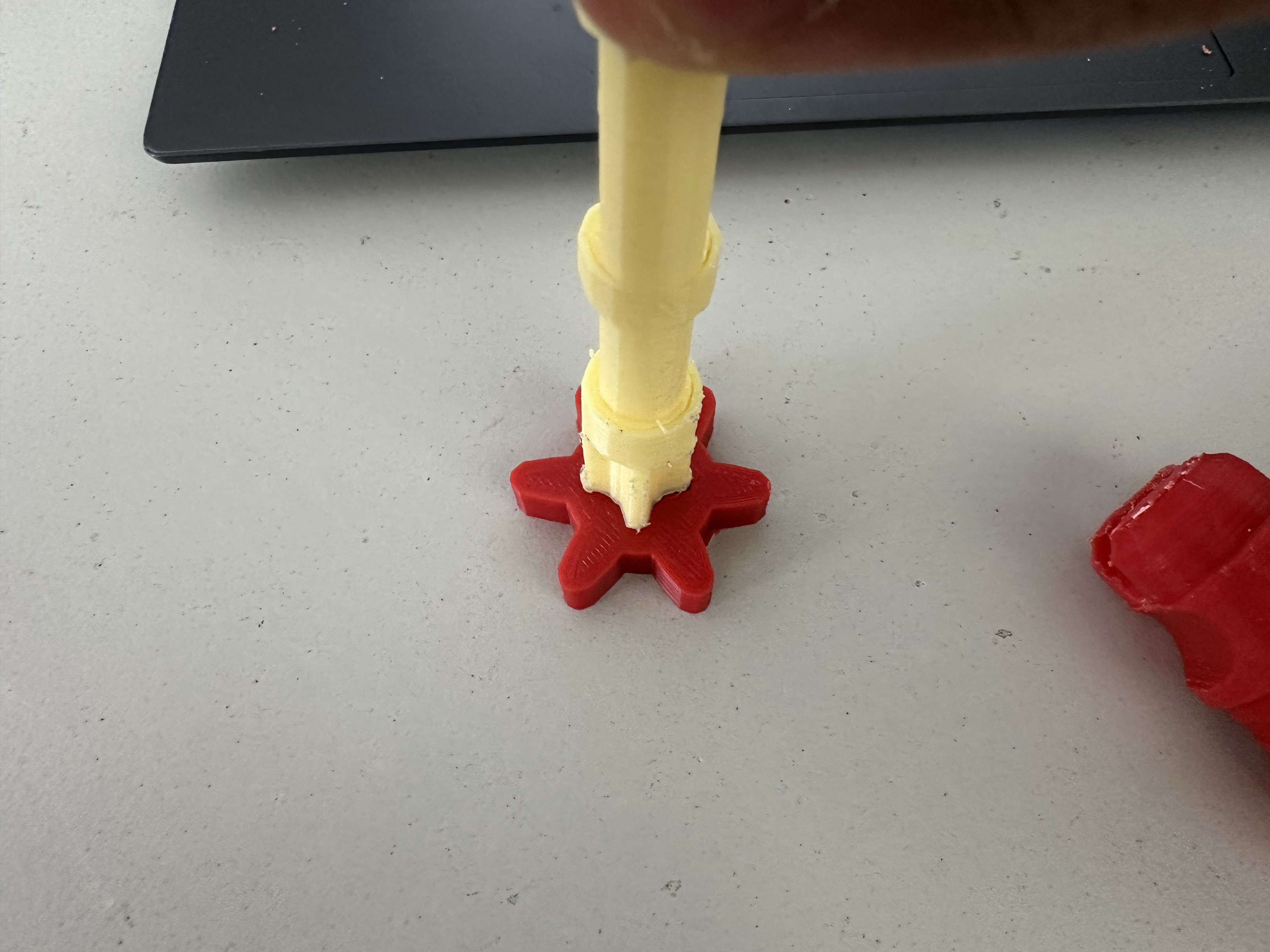
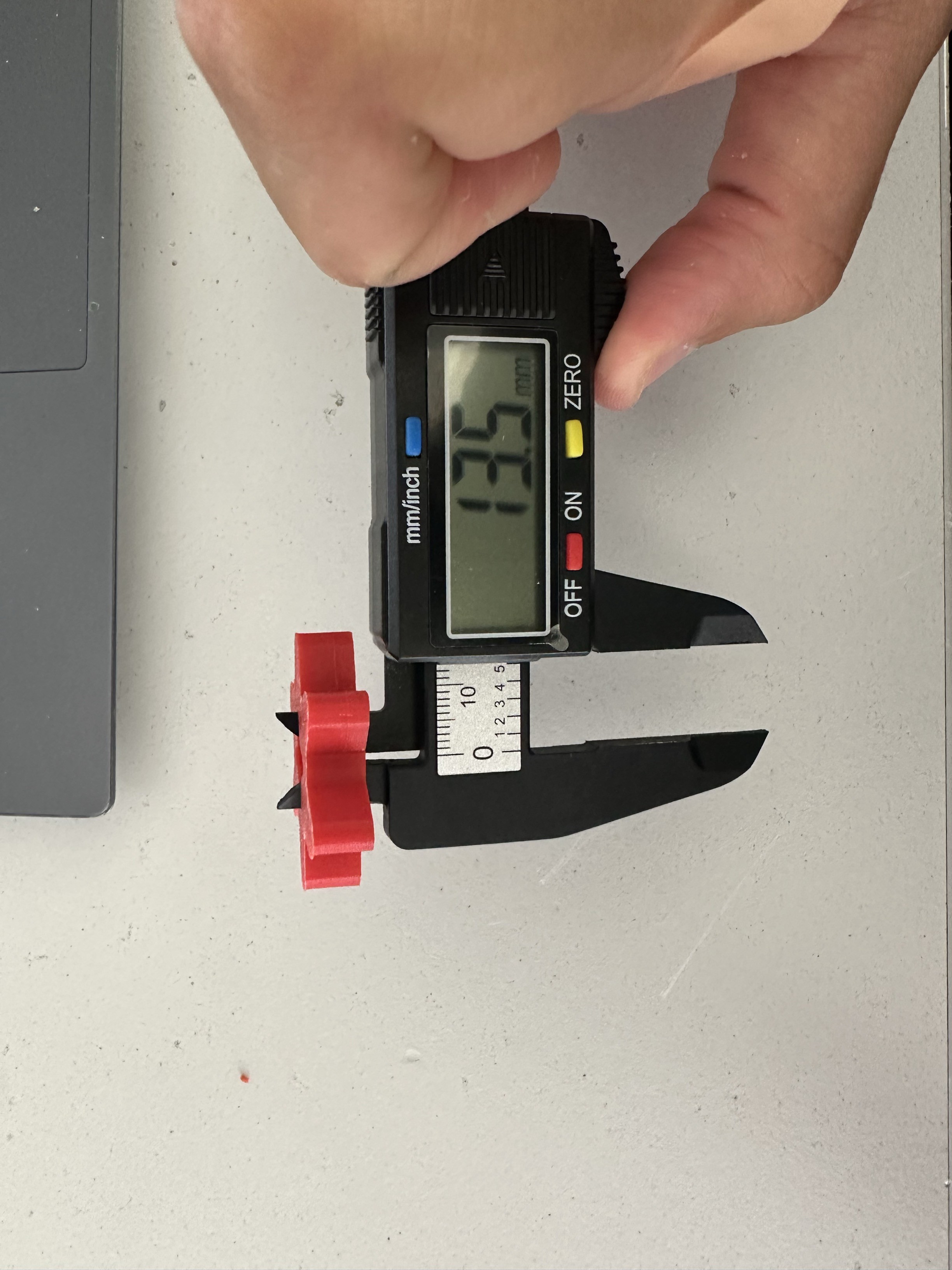 Meticulously measuring the actual pieces for redesigning the parts with the proper tolerances
 *Trying out how cams work are working before attaching the animal we want to move.
 Explanatory drawing