 Jesse Farrell
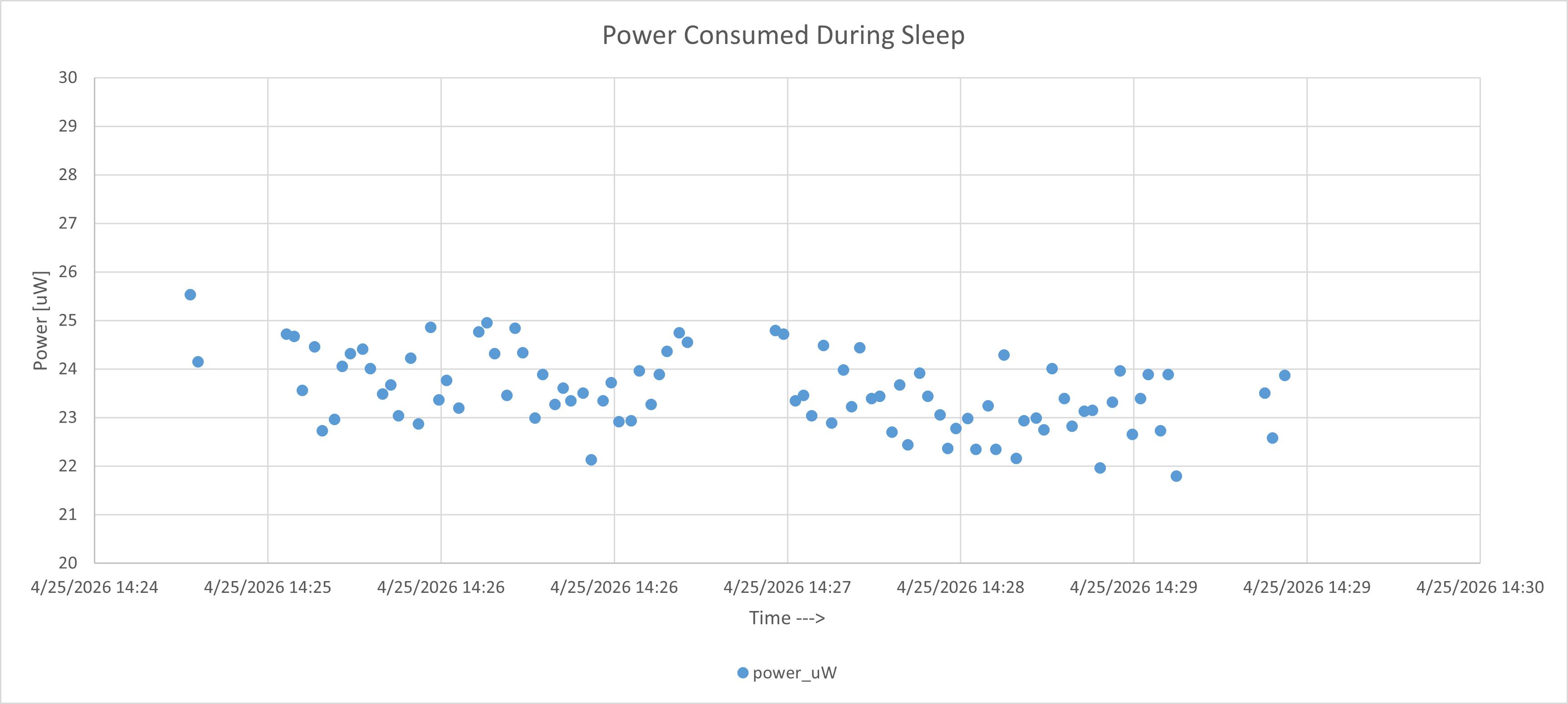
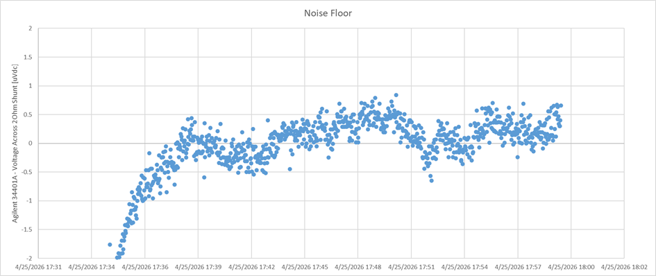
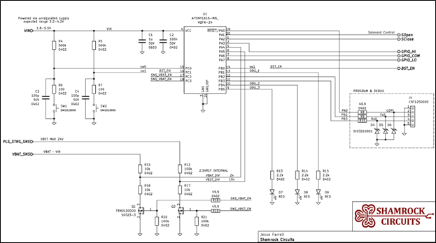
Power During Sleep: 24uW
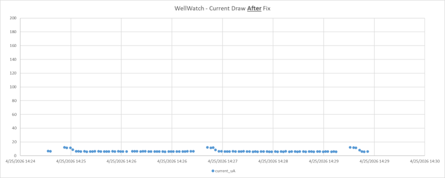
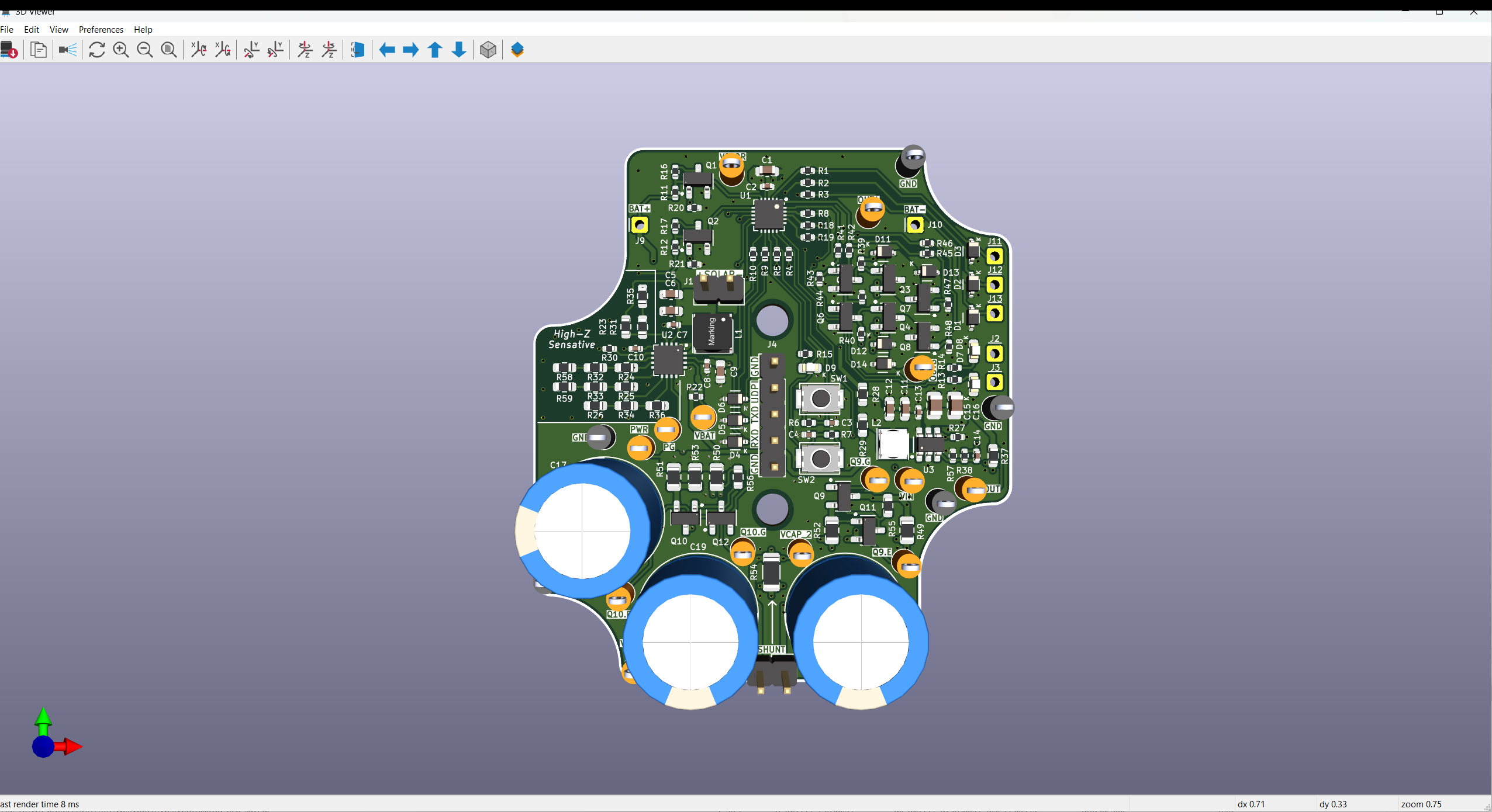
- Measured without solar. Powered from 3.8Vbat across 2 ohm shunt
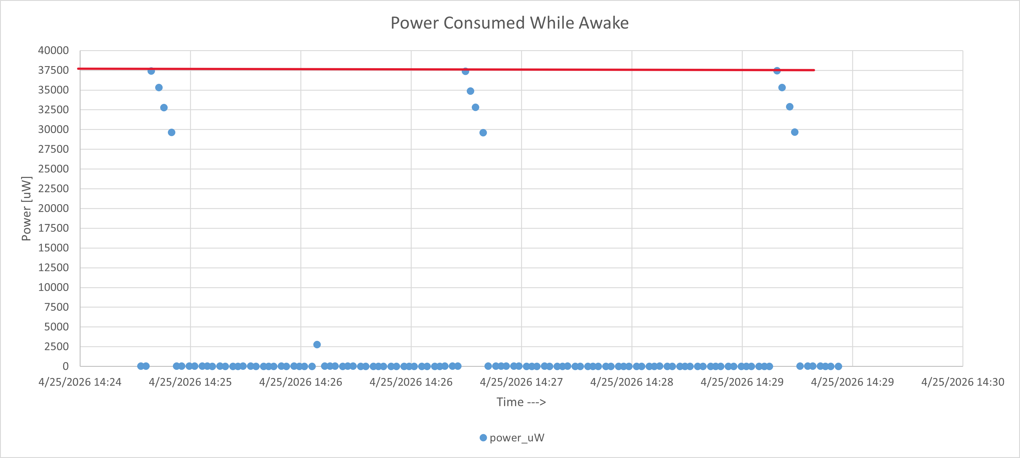
Power During Active: 38mW
- Same setup as above. This was the peak observed 1 second average.
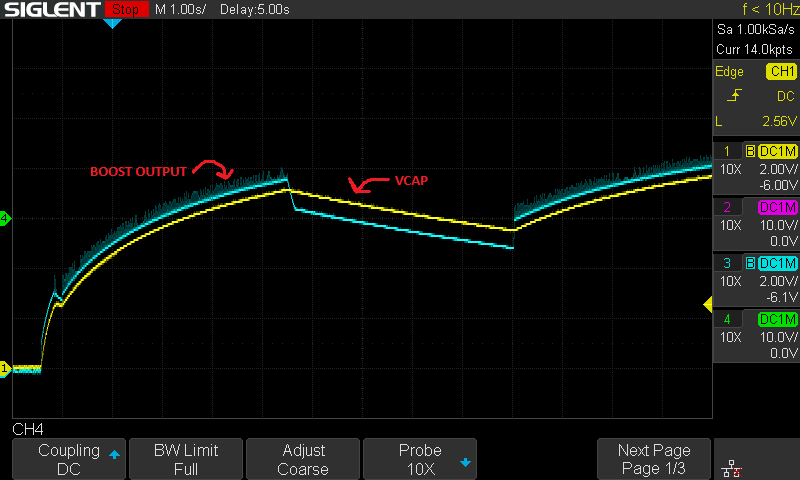
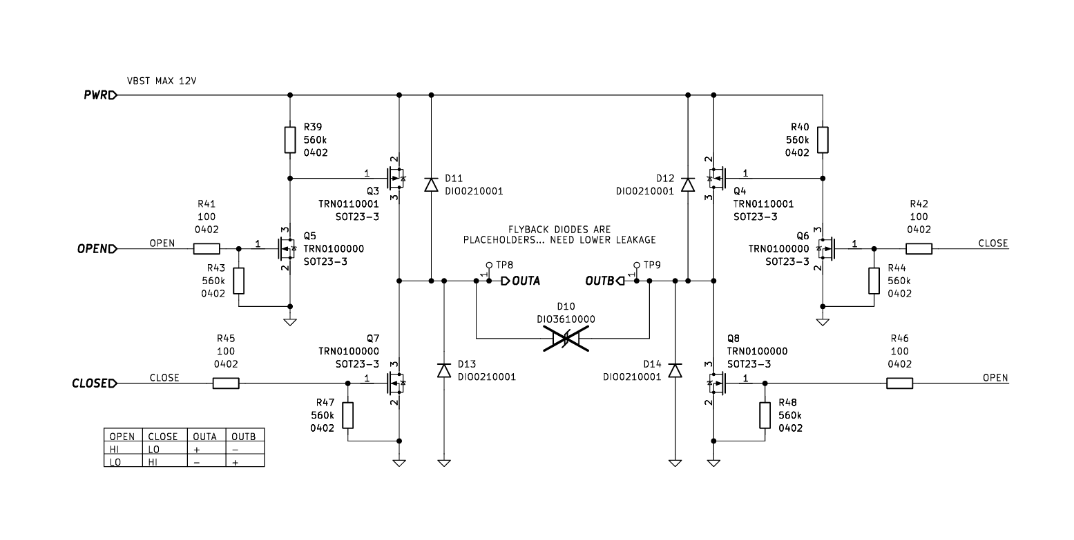
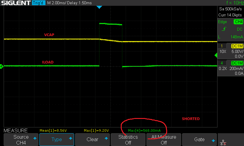
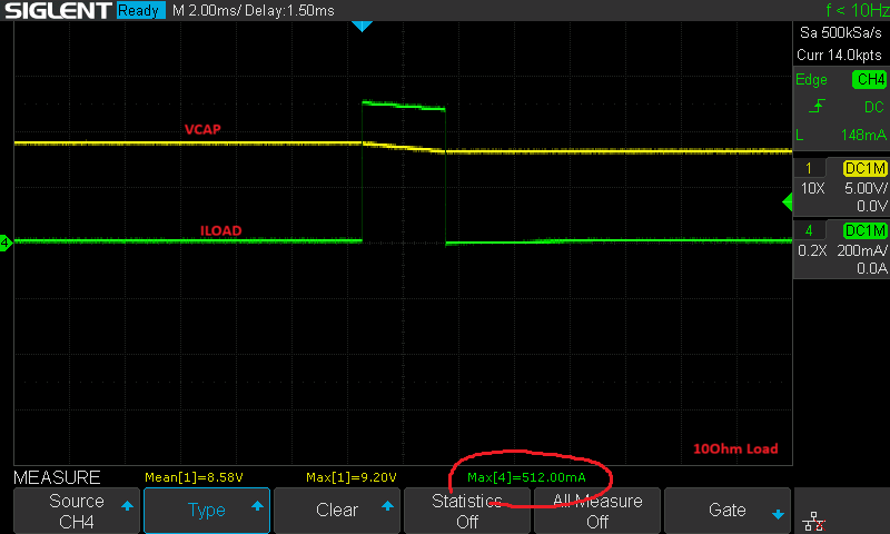
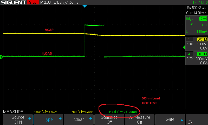
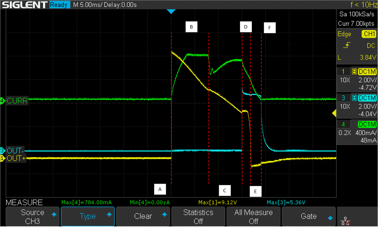
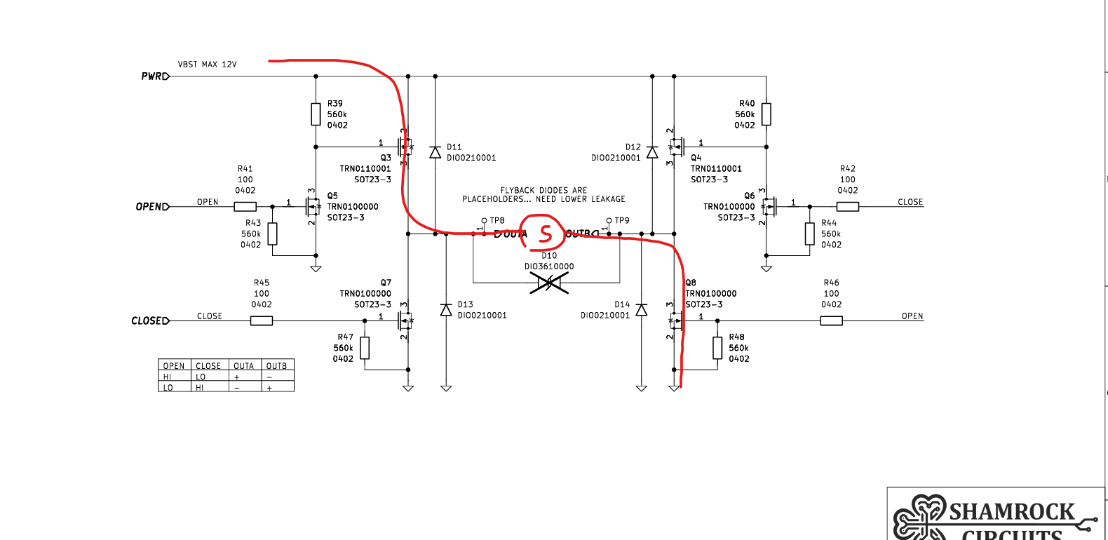
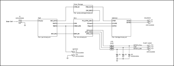
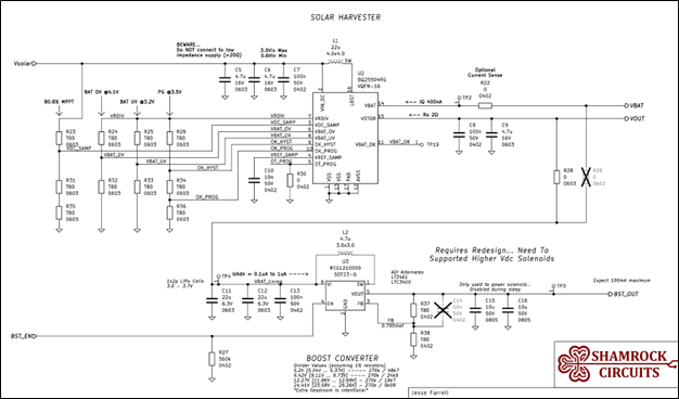
Peak Output Power: 17W
- This is the power delivered to the latching solenoid.
Battery Runtime: 115 days (3.6 months)
- Theoretical value without any solar present.
- 400mAh battery starting at 3.8V discharged to 3.2V.
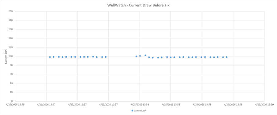
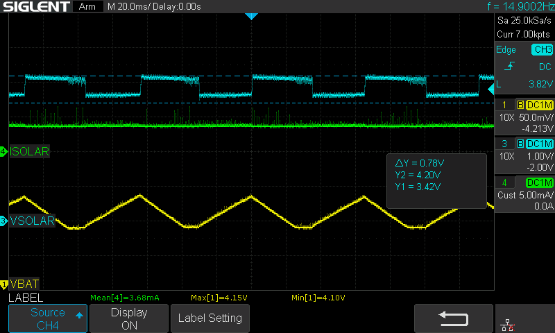
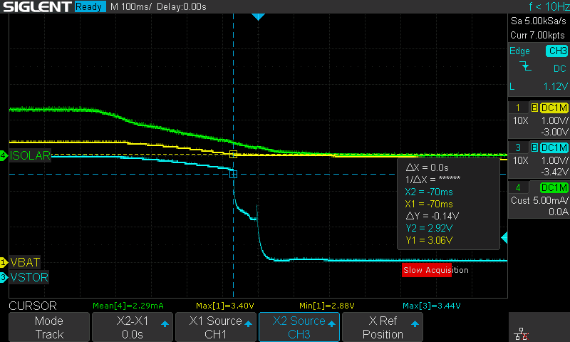
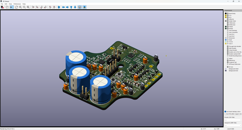
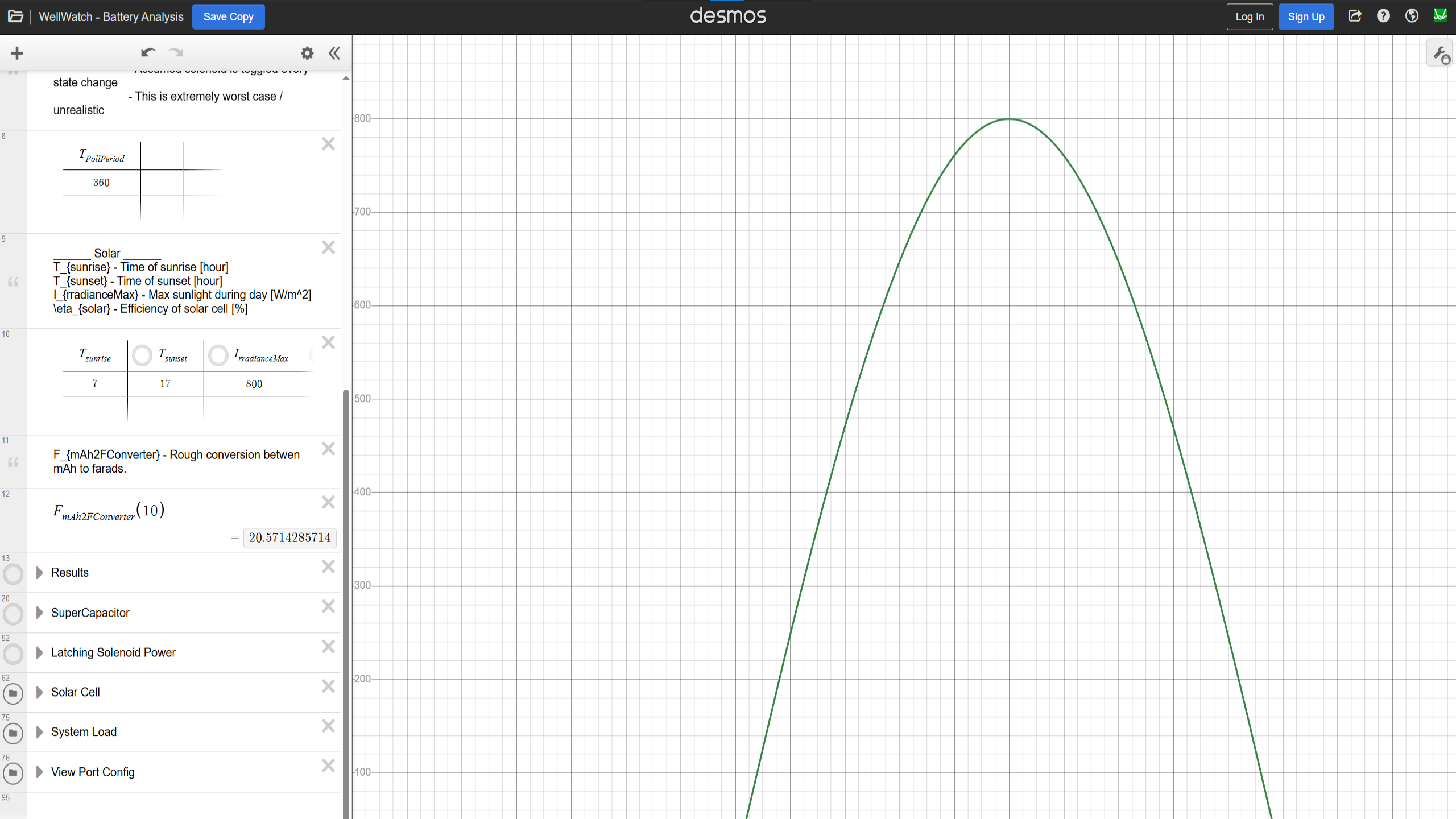
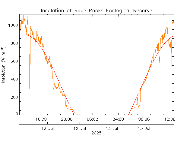
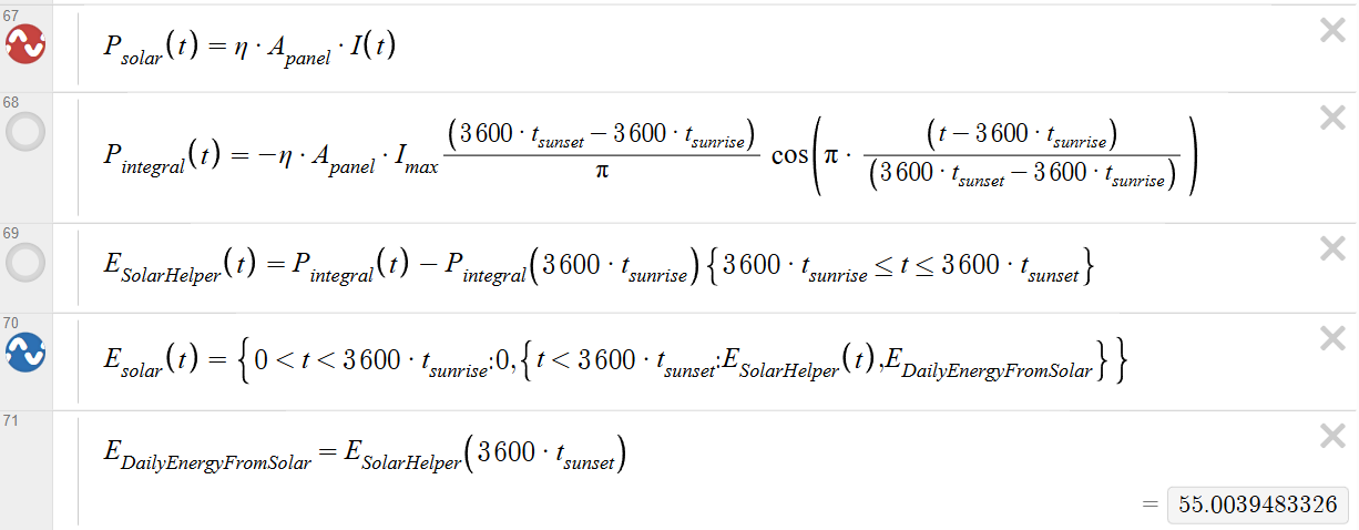
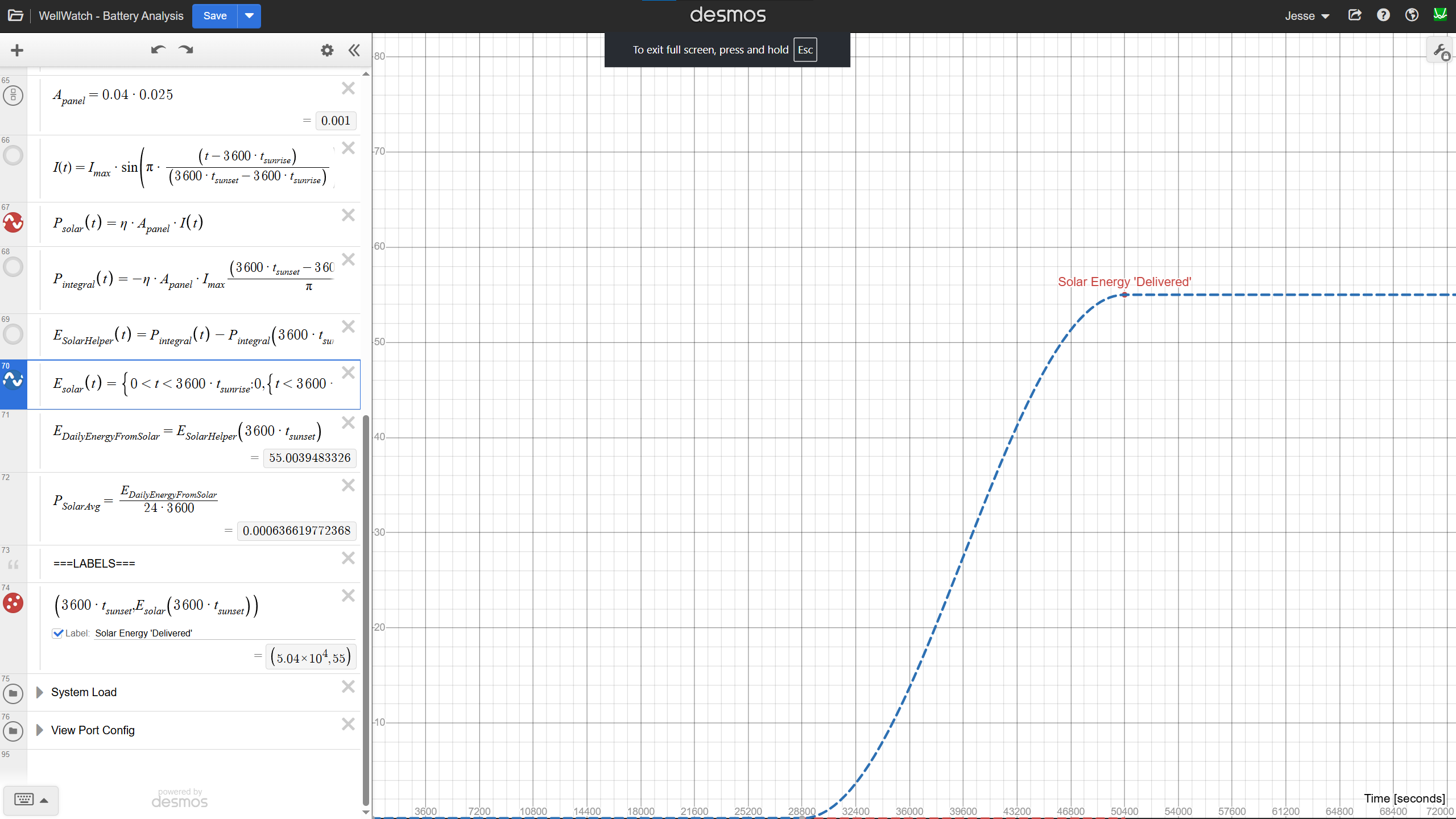
Some Data...
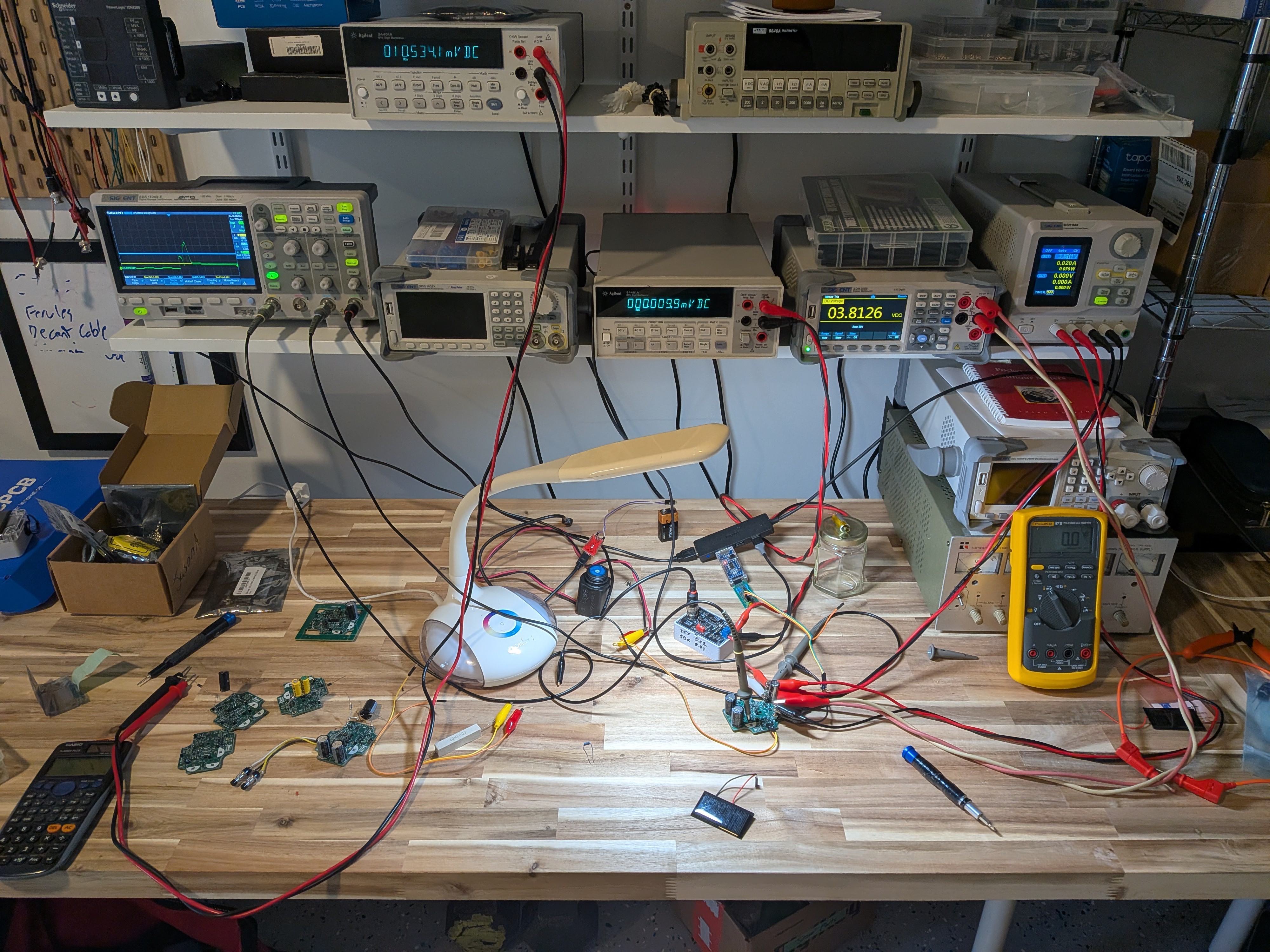
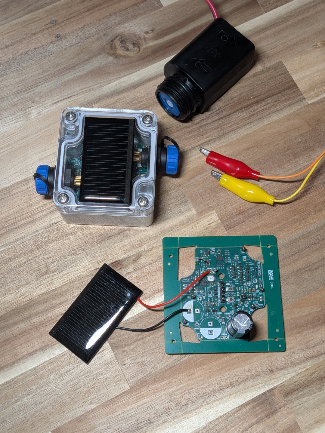
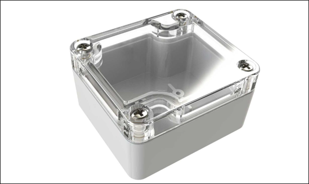
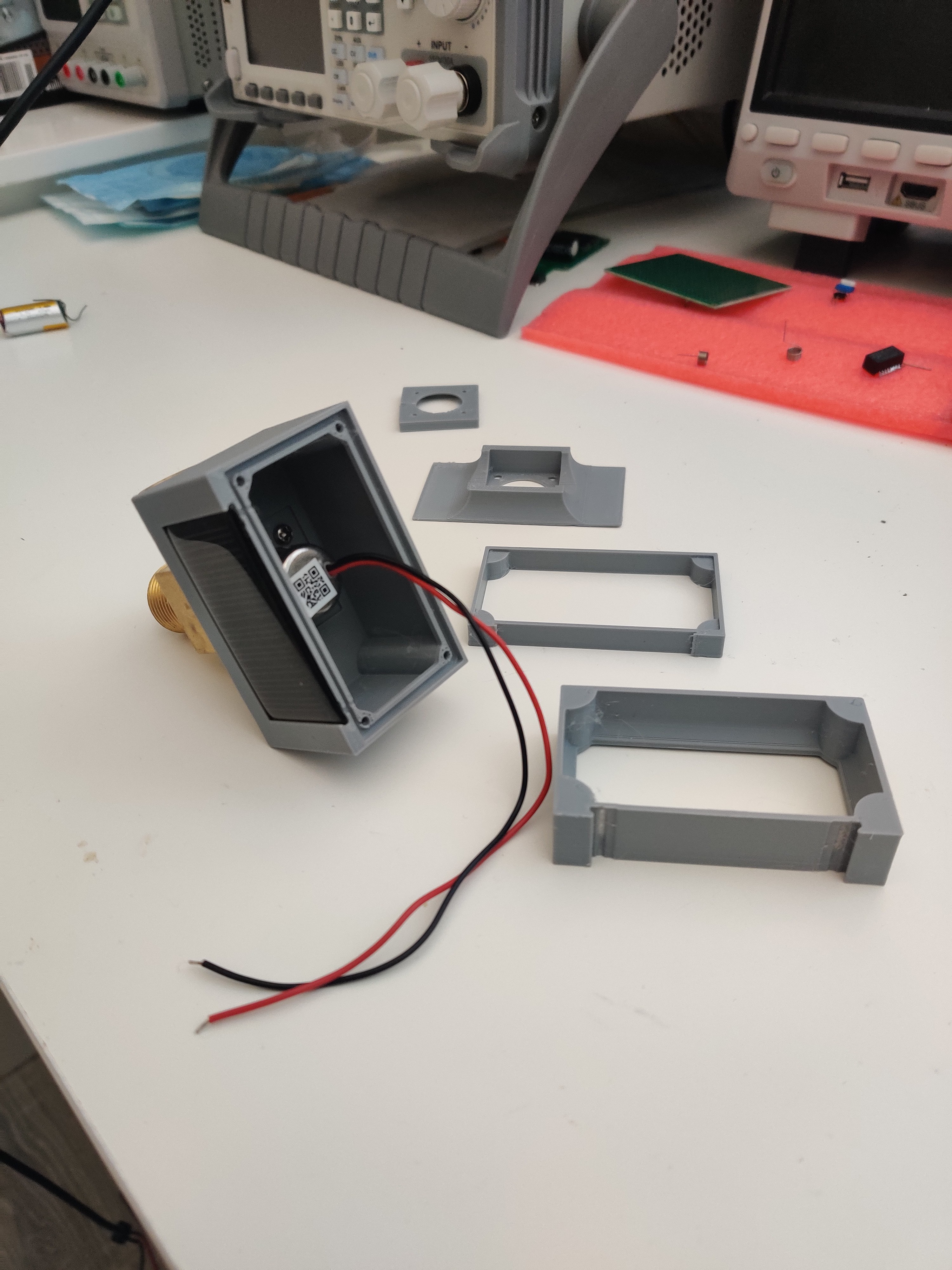
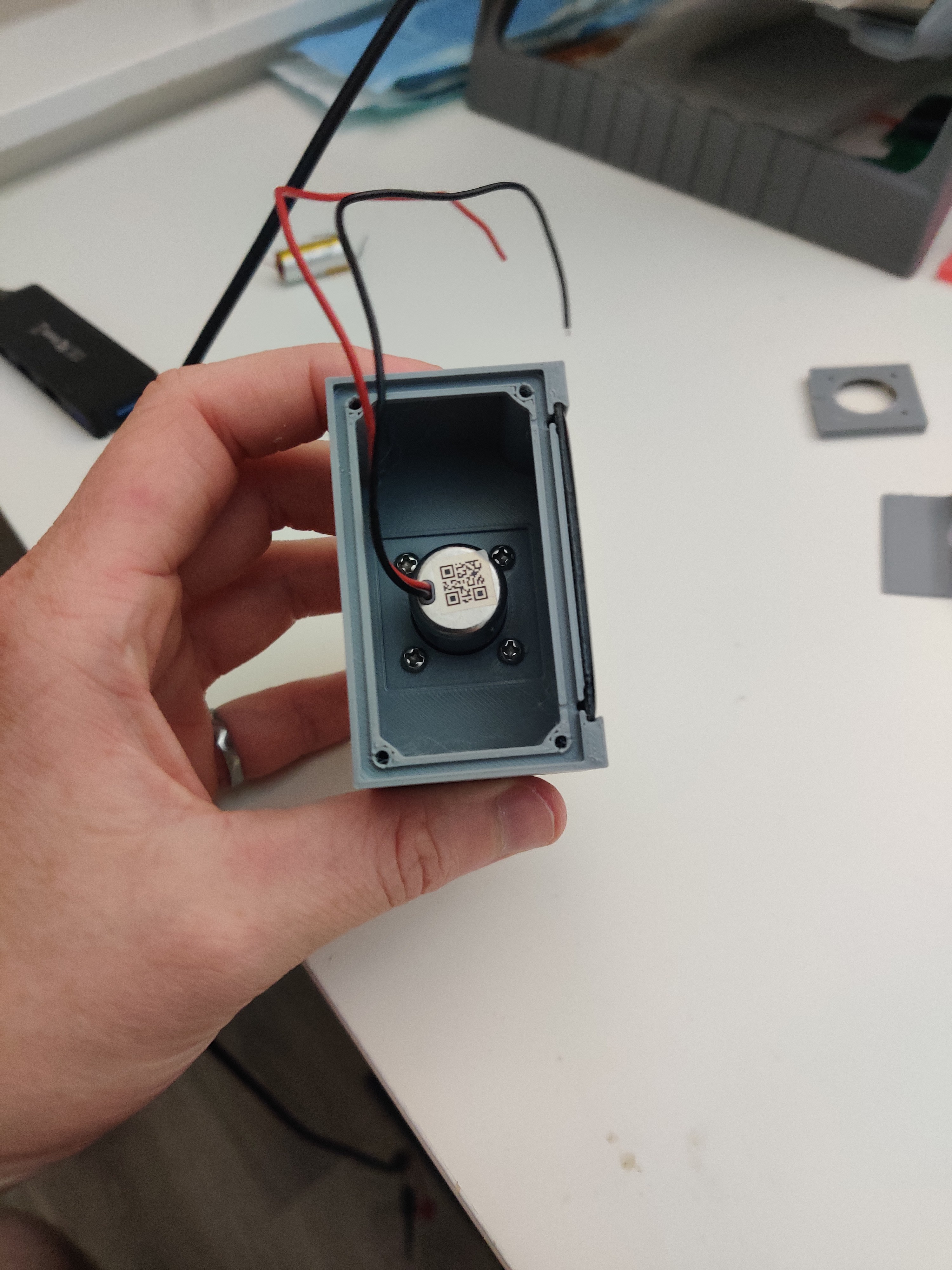
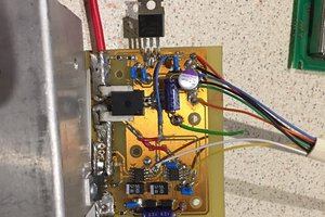
The setup...
Quick Demo...


 Saabman
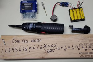
 Ted Yapo
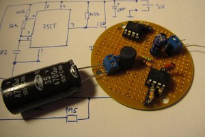
 jaromir.sukuba
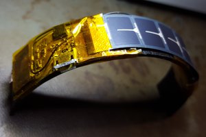
 DrYerzinia
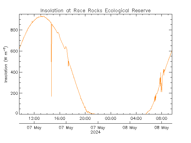