Tobias
-
Autostart, Labwc, project completion*, and what's next
11/09/2024 at 05:12 • 0 commentsHuzzah! I've finally worked out how to start all of the browser window I want, and have them automatically placed in different workspaces. If you've seen the previous logs you'll have seen how you can then tab through the different workspaces using the touch sensors to show all the different apps or HomeAssistant dashboards.
This took a huge amount of banging my head against the Wayfire (the window manager) documentation, and I'm honestly still not sure what an app_id or a window "title" is... But, it works! Huzzah!
![]()
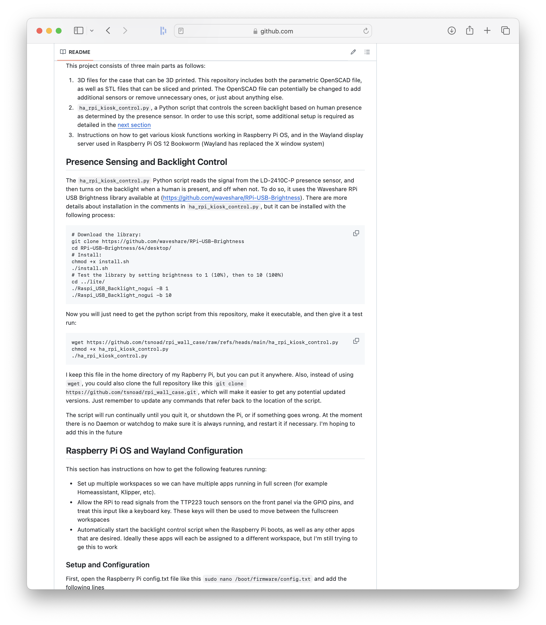
You can see all of the instructions in the readme in the GitHub repo here: https://github.com/tsnoad/rpi_wall_case
But then Hackaday put out this article about how Raspberry Pi OS has now abandoned Wayfire and has moved to something called Labwc for window management: RASPBERRY PI OS’S WAYLAND TRANSITION COMPLETED WITH SWITCH TO LABWC
![]()
So yeah, there are a bunch of questions I don't have the answer to:
- From what version will Labwc be the default? No idea, the announcement is completely vague
- If I apt-upgrade will Labwc be set as the default? No idea
- Is there any documentation for Labwc? Ha, no
So at some point the autostart script will stop working, so I guess I'll find out when that happens. This will likely affect the autostart settings that automatically open the defined browser windows, as well as the way the touch sensors are used to change workspace. I don't believe it will affect the presence sensor and the automatic backlight dimming (but who really knows...)
There isn't really any good documentation for Labwc, so I don't have any plans to update the script to use it, at least until this thing on my wall breaks, and I'm forced to do something about it. Sigh...
Anyway, setting all of that crap aside, this project is now pretty much complete. There are a few things that I still want to do, specifically:
- Reprint the case now that I've solved the z-wobble on my 3d printer
- Redesign the case so that a light sensor can be included, as well as making the sensor brackets more modular. This might include a mounting position for a microphone board that could be used by Rhasspy or other voice assistants
- Redesign how the face is mounted. I'm not a huge fan of how the screws are visible on the front, and I really don't like the bed texture on the front of the faceplate. I do want to redesign it to be attached with magnets which could solve both of these issues
But, I don't have a timeframe for any of that, and I wouldn't expect it anytime soon.
So with that said, thanks everyone for the views and likes. If anyone has printed their own version of this, I'd love to see it, and until next we meet, have a good one!
-
Button inputs, Wayfire, autostart, and what's next
10/18/2024 at 09:15 • 0 commentsAfter leaving the front panel buttons unimplemented for a while, a really helpful comment from @ryan-worrell got me thinking about how they could be set up. The way I decided to go was to use the buttons to switch back and forth between a few different browser-based apps. In my case this was Homeassistant, and Klipper for my 3D printer. Here's what it looks like in action:
![]()
And while we're looking at animations, here's what it looks like when the presence sensor detects that I've walked away, and slowly turns of the screen backlight:
![]()
Instead of reading the touch sensor buttons in a Python script, it was easier to use a dti_overlay to tell the RPi to treat the GPIO input like a keyboard press - so that when the sensor is pressed, it is just like pressing the KEY_NEXTSONG key on a keyboard. The next step was configuring Wayfire to know that it should switch workspaces when this key is pressed.
Another really important feature I wanted is for all of my desired apps/browsers/windows to open automatically when the RPi boots up. Ideally this would also include the apps being set up in the right workspace, but so far that has proved challenging, and something I'm still working on.
So, how is all of this set up? I've added all of the steps to the README on the GitHub page, which you can find here: https://github.com/tsnoad/rpi_wall_case
![]()
![]()
So, what's next? To be honest, I'm really not happy with how the front panel looks when it's 3D printed, mainly because of the printer bed texture. At some point I want to redesign the 3D files, which could also include adding a ambient light sensor, but don't expect this soon. With the exception of getting the autostart script to put the windows where I want them, this project is pretty much complete.
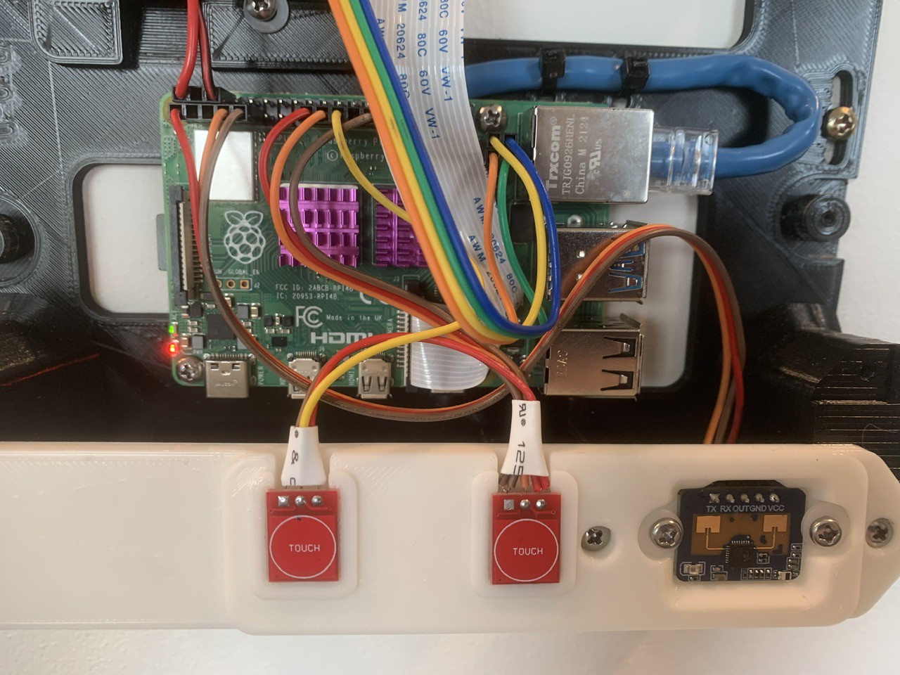
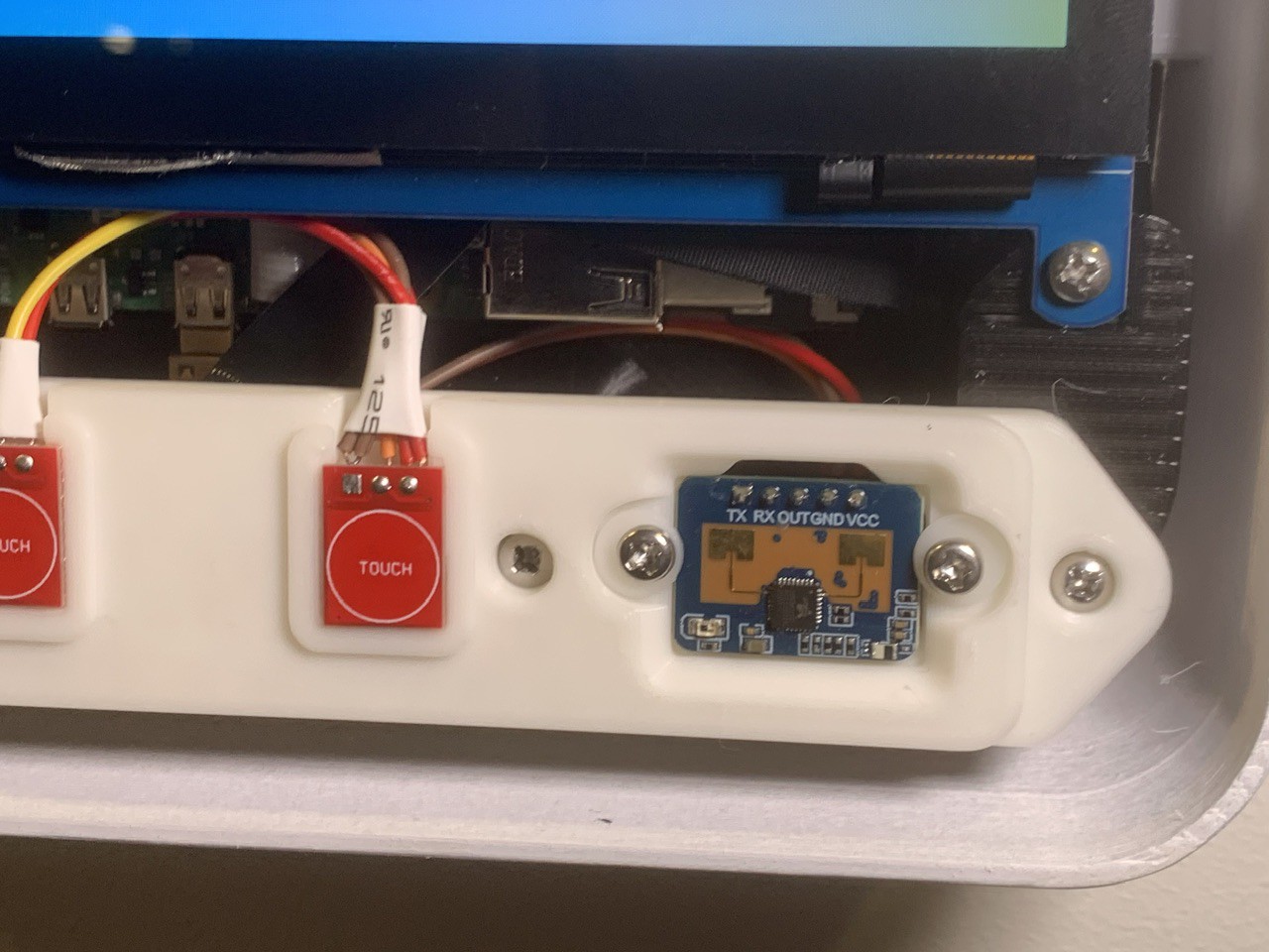
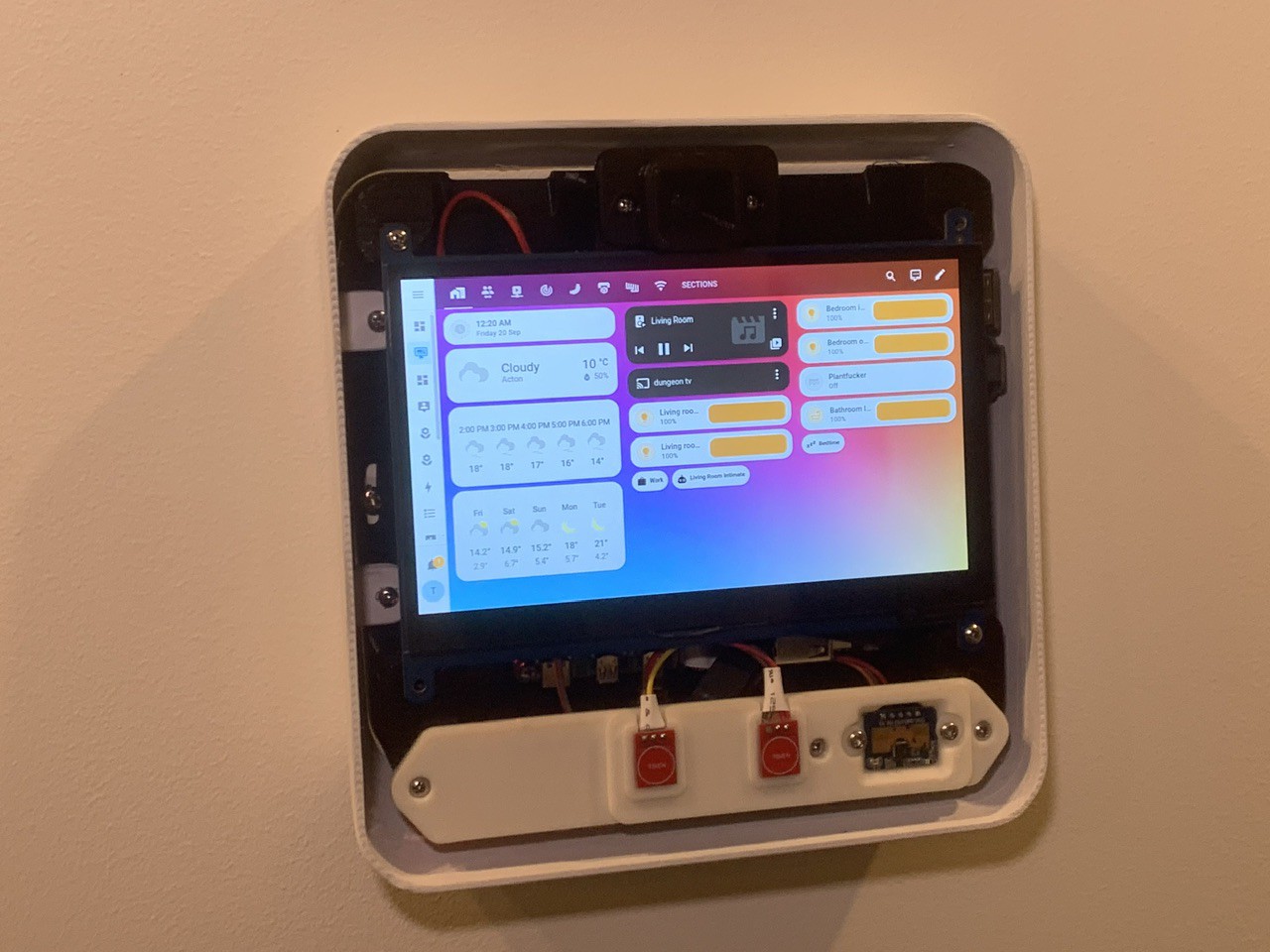
Finally, @ryan-worrell asked how the presence and touch sensors are wired to the GPIO pins, and unfortunately this isn't really something I've documented yet. Here's a (not very useful) picture of the wiring, as well as a (hopefully more useful) table of the pin connections:
![]()
RPi 4 GPIO Pin # Pin Desc Connected to 1 3.3V VCC pin of LD2410C-P presence sensor 3 GPIO 2 Not used 5 GPIO 3 Not used 7 GPIO 4 OUT pin of LD2410C-P presence sensor 9 GND GND pin of LD2410C-P presence sensor 11 GPIO 17 Not used 13 GPIO 27 Not used 15 GPIO 22 Not used 17 3.3V VCC pin of both TP223 touch sensors 19 GPIO 10 I/O pin of right TP223 touch sensor 21 GPIO 9 I/O pin of left TP223 touch sensor 23 GPIO 11 Not used 25 GND GND pin of both TP223 touch sensors -
Presence Sensing
09/23/2024 at 07:17 • 0 commentsPresence sensing was always a key feature for this project, with the goal to have the screen turn on when someone approaches, and then automatically turn off when not in use.
Thankfully the presence sensing is really easy to achieve using an LD2410C-P sensor. As far as I understand it, this awesome sensor uses radar to essentially measure the amount water it can see, meaning that it's not affected by motion, sunlight, etc, and only triggers when a big sack of water is standing in front of it - ie a human being. The best part is that it outputs a simple low/high IO signal based on presence being detected. So far, the sensor has worked fantastically and flawlessly.
The sensor is mounted behind the faceplate which doesn't seem to change the way it performs at all. The datasheet has more information about radomes, but 0.4mm of PLA seems to work fine.
![]()
![]()
The biggest challenge was getting the screen to turn off and on. I'll blame a lot of this on the change from X to Wayland in RPi OS, but I've found that almost any internet article or forum post before 2023 no longer applies (and yes, I understand the security reason for the change). I think this is just something that will just improve over time.
Anyway, after a lot of trying and failing with Xrandr, WL-randr and DDCUtil, I found the correct version of Waveshare's RPi-USB-Brightness library. Unfortunately it seems to be completely closed source, but from what I understand it controls the backlight by serial communication over the USB port, and so far it works adequately. The alternative is to solder a wire to the screen's backlight PWM port, and then send a PWM signal from the RPi.
So, to bring it all together, I created a Python script to read the GPIO pin, and turn the screen off and on as necessary with a nice fade-in effect. You can view and download this script from the Github repo here: https://github.com/tsnoad/rpi_wall_case/blob/main/kiosk.py. This script will also be used to read input from the touch-sensitive buttons, but this isn't implemented yet, partially because I don't know if the buttons will actually be useful.
At present the script has to be run manually after startup (so does the browser that points to Homeassistant). At some point I will set this up as a daemon, but at the moment I just have it set up as a RPi OS menu item so that a keyboard is not needed.
![]()
That's all for now, but still on the to-do list are:
- Project log about getting Power over Ethernet working
- Project log about painting, sanding and finishing the case
-
The RT9460, RPi PoE, and a slow descent into madness...
09/02/2024 at 07:17 • 0 commentsSo, while the procrastinator in me was happy to have a USB cable running up the wall, the perfectionist in me could only stand that for a couple of weeks. Thankfully it's fairly easy to run a cable through my walls, and at first I had a 4 meter cable running to a 5 volt power supply. Of course, it didn't take long to find out just how much resistance there is in 22AWG cable at low voltage.
The plan was always to switch to PoE, and in my inveterate browsing of Aliexpress, I came across the RT9400/RT9460 PoE module. The official RPi PoE module might be a better option, but the RT9460 has the advantage of fitting into my tight space constraints, and it's nice that it's a fair bit cheaper. I've also seen people using the common DC-DC modules to power a Raspberry Pi, and at the end of the day this really is just a DC-DC converter. It does, however, have an isolation transformer, and it's designed to operate at 48V, which I think is on the high end for most of the cheap DC-DC converter modules.
The real problem is that there isn't any good information on how to use it to power a Raspberry Pi. Adafruit sell a PoE module with a different part number, but which looks the same and has the same pinout, but I had absolutely no luck trying their suggested wiring.
So, with all of that said, I'll show you how I wired a RT9460 PoE module to supply power to my Raspberry Pi. But first, an important note: I'm using a RPi 4, and I can't tell you if these instructions will also work for an RPi 3, 5, or anything else (oh, and in case it needs saying, I can't guarantee that if you try this you won't set fire to your RPi, workbench, ethernet cable, fingers, house, or anything else - playing with cheap Aliexpress electronics can be a dangerous game).
First we must ask... what is the PoE connector? Essentially it's a direct connection to the ethernet pins in the RJ45 jack. More accurately, it's a direct connection to the centre taps of the coupling transformers for each ethernet pair, which is good, cause that's what we need to the power from the power over ethernet.
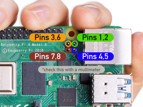
So now we just need to work out which pins are which on the Raspberry Pi 4 PoE header. A quick bit of poking with a multimeter let me work out which PoE header pin corresponded to which ethernet pins:
![]()
My PoE switch provides +48V DC on pins 4&5, and negative on pins 7&8, which according to wikipedia is Mode B PoE. A bit more poking with the multimeter (watch out for arcs at this voltage!) confirms the pinout which, is nice.
Now we just need to hook up the RT9460 PoE module, but here we run into the next challenge. The data sheet for the RT9460 is clear about which ethernet pin needs to be connected to which RT9460 pin, but then provides wiring diagrams for 100M and 1000M ethernet that have conflicting wiring. Specifically, the data sheet says for 100M, VA1 and VA2 of the RT9460 should be connected to ethernet pins 1,2 respectively. for 1000M, VA1 and VA2 of the RT9460 should be connected to ethernet pins 7,8 and 4,5. So which should we use?
At this point it's probably worth noting that I don't have any idea how PoE works, and I'm just prodding things until they work. But, according to the data sheet, the RT9460 is not polarity sensitive, in getting this to work I tried just about every combination, and the module didn't fry...
So, at last we get to the good stuff, an actual wiring guide. Here's what worked:
- RPi PoE header (ethernet pin 4,5) - to - RT9460 VA1 (pin 1)
- RPi PoE header (ethernet pin 7,8) - to - RT9460 VA2 (pin 2)
- RPi PoE header (ethernet pin 1,2) - to - RT9460 VB1 (pin 3)
- RPi PoE header (ethernet pin 3,6) - to - RT9460 VB2 (pin 4)
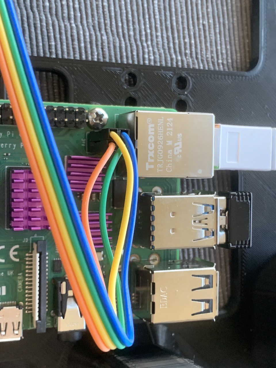
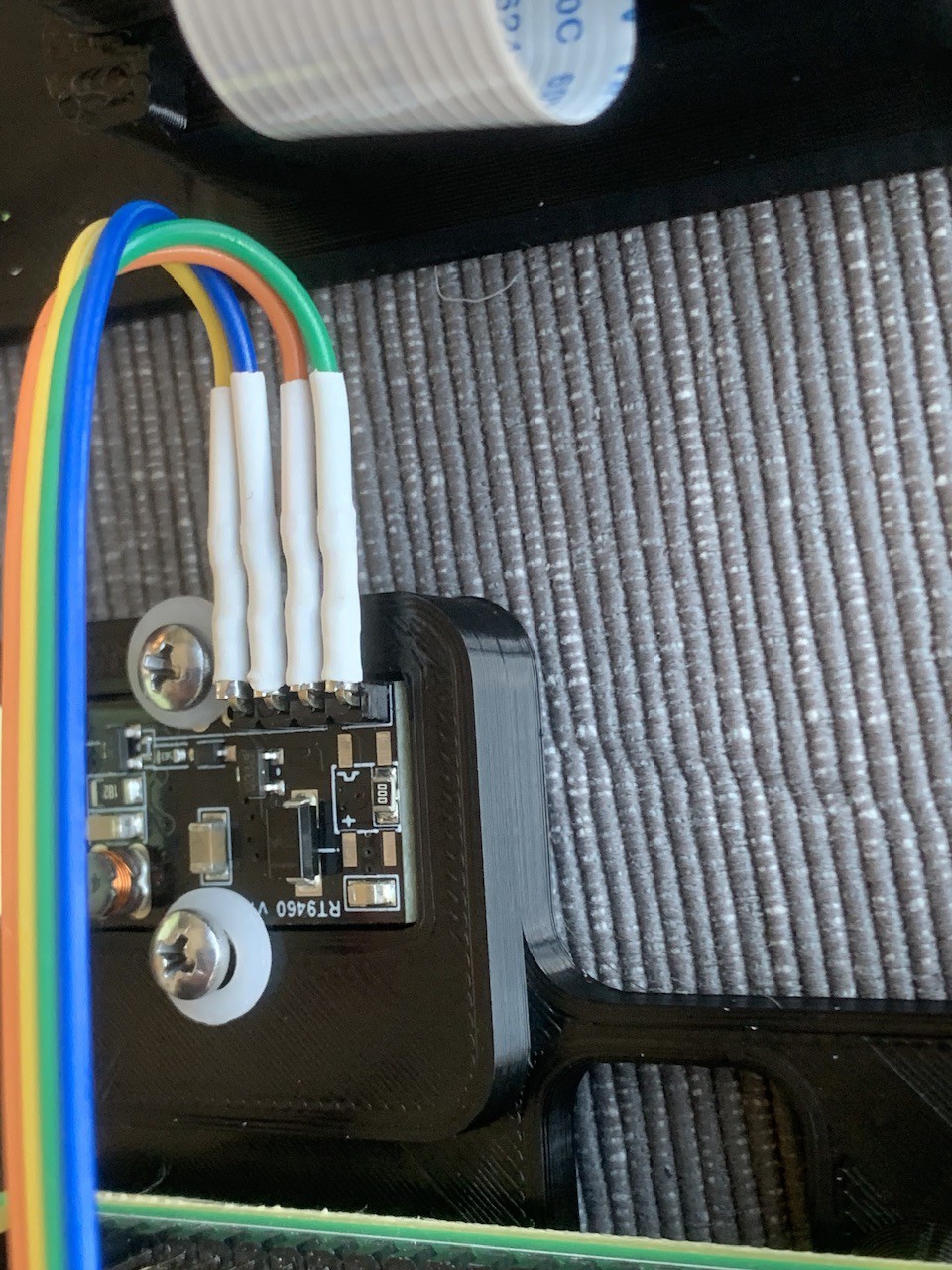
And here's what it looks like in practice. Important not, the color of these wires means nothing - I soldered them on before I double checked the pins (sigh):![]()
![]()
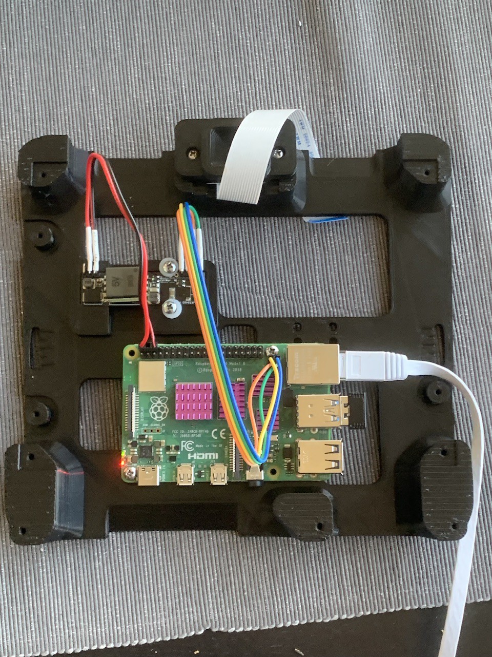
And here's the overall view:
![]()
Thanks for coming along on this alarmingly long journey, and leave you with some last notes:
- breadboard hookup jumper wires worked great for the 48V input into the PoE, but got alarmingly warm when I tried to use them on the 5V output - the current at 5V is way too high for these jumpers, so solder up something else
- According to wikipedia: "The PSE [the Power Sourcing Equipment i.e. the PoE switch or injector], not the PD [the Powered Device], decides whether power mode A or B shall be used. PDs that implement only mode A or mode B are disallowed by the standard". This would seem to mean that the RT9460 isn't compliant with the PoE standard. I don't really know if this will work with any other PoE power supply.
- As you might of guessed, the sum total of my experience with PoE has come from wikipedia and my multimeter, so proceed with caution. If you think I've made any mistakes, please don't be shy of saying so in the comments, so we can all learn together!
-
Assembly and Todo
07/22/2024 at 15:31 • 0 comments![]()
Here's a quick animation of how all the components fit together.
There are still a few items to do:- clearance on the mounting bosses for the wall need to be adjusted
- Need to design a mount for a PoE board (still waiting for parts to arrive)
- Need to clean up and comment OpenSCAD file
- Need to complete Python script that deals with the presence and touch sensors
- Need to work out how daemons work in Rasbian Bookworm (yeah, I know why it's important, but at this stage I'm really starting to hate Wayland...)
Raspberry Pi Wall Panel
A wall panel style case for a Raspberry Pi including presence sensing and touch input