The project has received incredible feedback since the last post, especially after being featured on Hackaday (check it out here). Many people have asked for updates through various channels, so here I am to share the latest progress, challenges, and lessons learned!
Special Thanks to PCBWay
First and foremost, a huge thanks to PCBWay, who sponsored the first PCBs with the correct color, thickness, and finish. A special shoutout to Liam for making this support possible! Without them, this project wouldn't have progressed so smoothly.
Soldering Process
The components were soldered using a improvised hot plate and low-melting-point solder paste (138°C). Due to the small components and compact design, a lot of patience was required to ensure proper alignment and avoid shorts.
PCB Design Errors and Improvements
No project is without challenges, and this one was no exception. Here are some areas for improvement in future revisions:
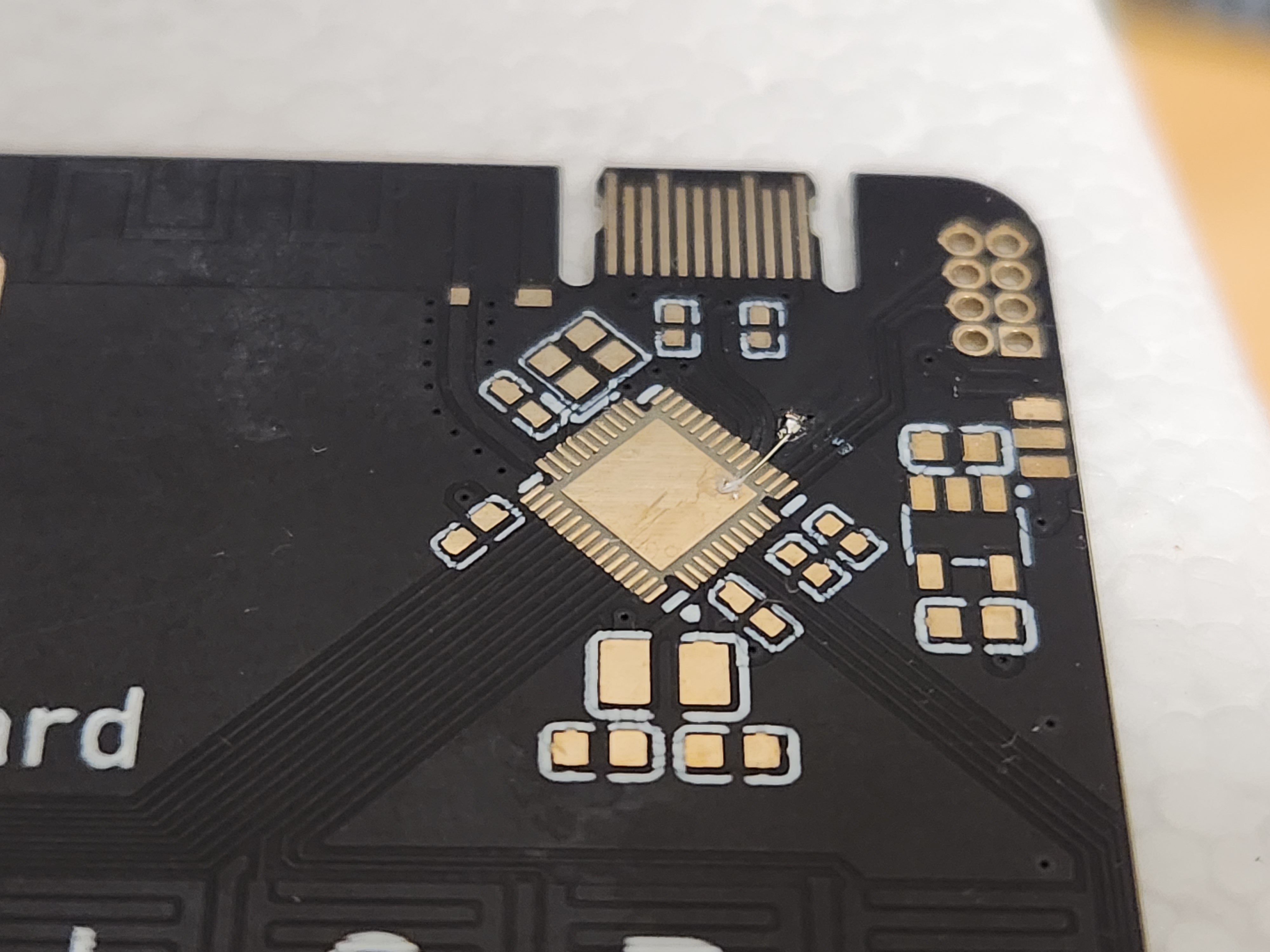
Microcontroller GND connection error:
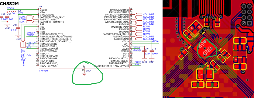
The main GND connection ended up being disconnected on the manufactured PCB. This happened because the EP (Exposed Pad) of the microcontroller should have been connected to the GND plane underneath the chip, but this was overlooked during routing, so i have to do a quick fix:
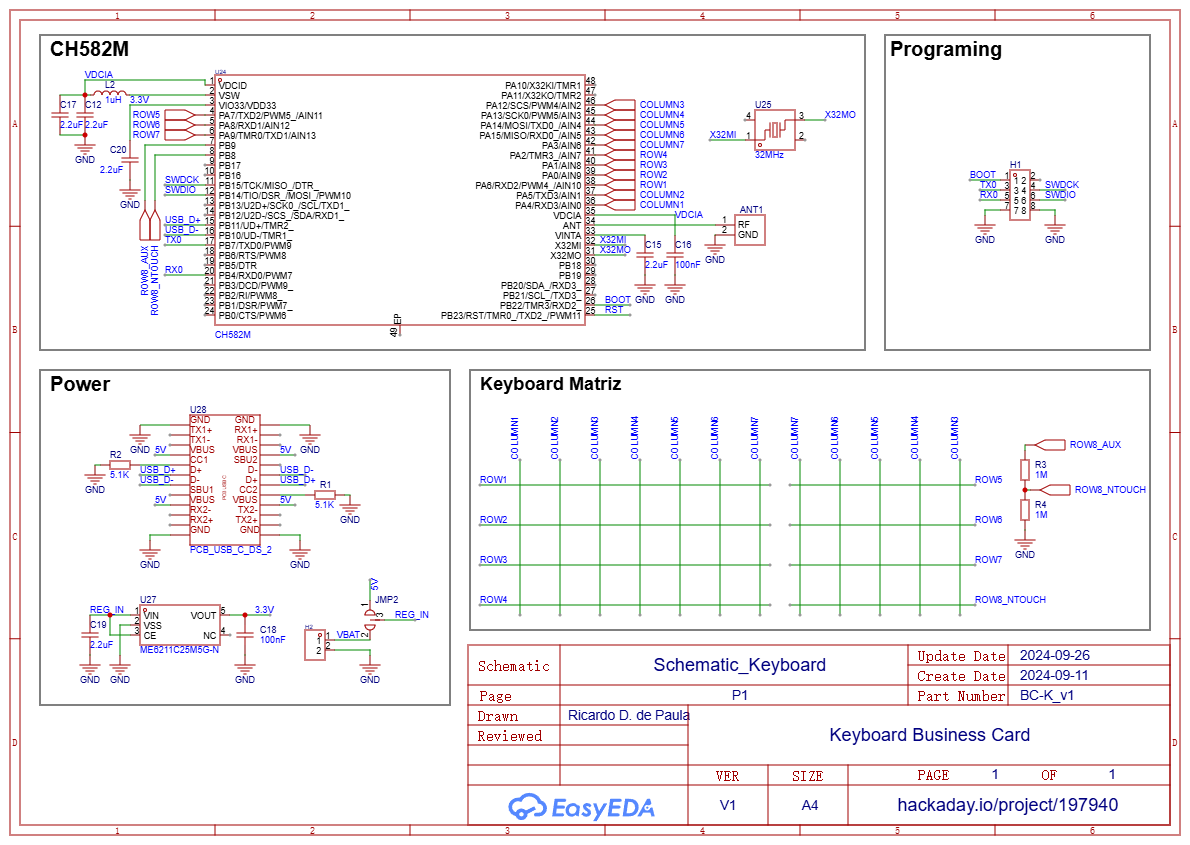
The error has already been corrected in the schematic and PCB in the EasyEDA project:
Lack of indicator LEDs:
Initially, I omitted LEDs to reduce costs. However, I later realized that having a power LED and another to indicate Caps Lock or other functions would have been very useful. In the end, the cost-saving decision was negligible and not worth it.
PCB thickness and USB-C fit:
I opted for a 0.6mm thickness since the USB-C connector documentation specified 0.7mm. Unfortunately, this 0.1mm difference resulted in a slightly loose connection. Since PCBWay doesn’t offer 0.7mm PCBs, 0.8mm might have been a better choice for a more secure fit.
Entering the Firmware Realm
Now it's time to dive into firmware development! This microcontroller does not support the Arduino IDE, which might have made development faster and more convenient. Because of this, I'm using WCH's development environment, MounRiver Studio.
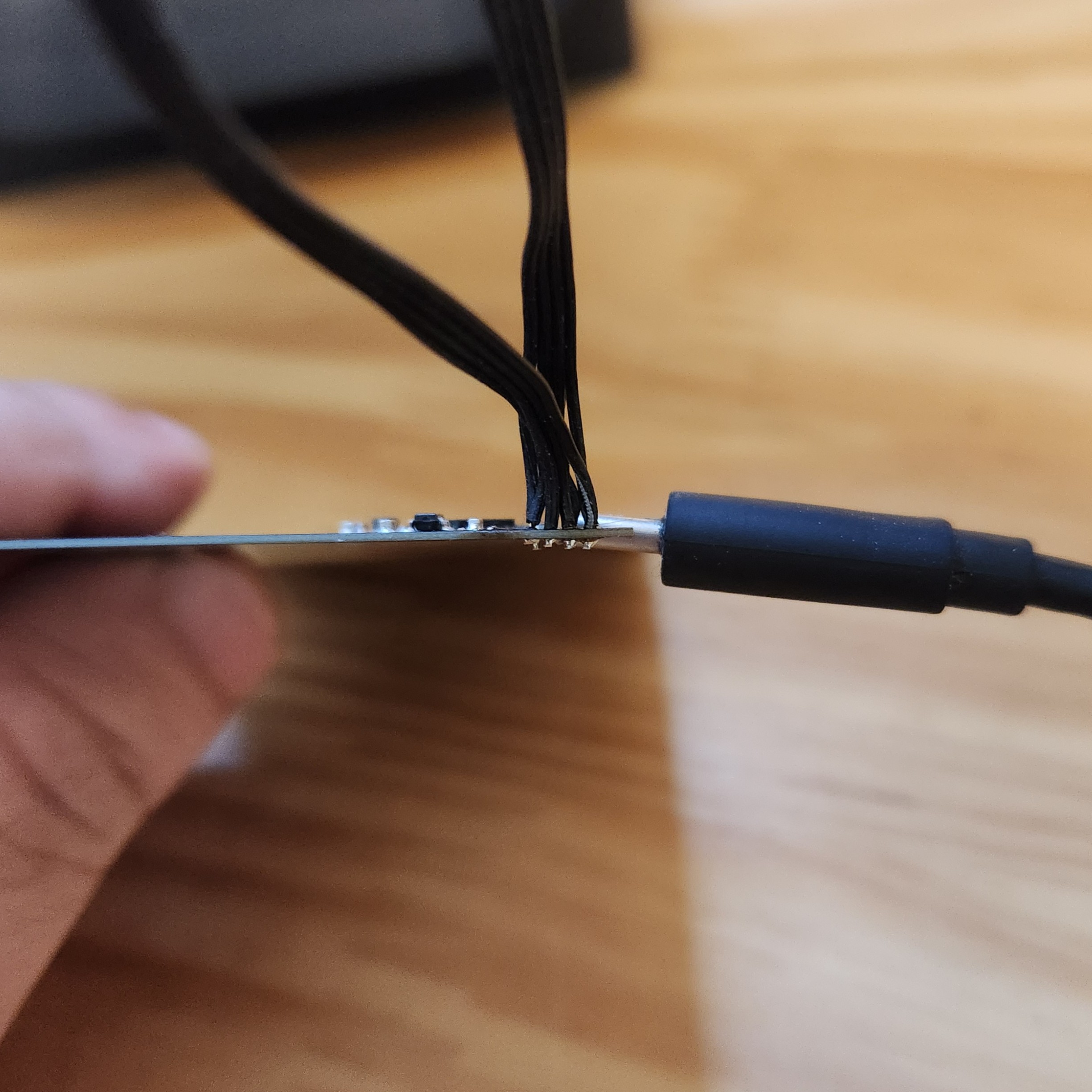
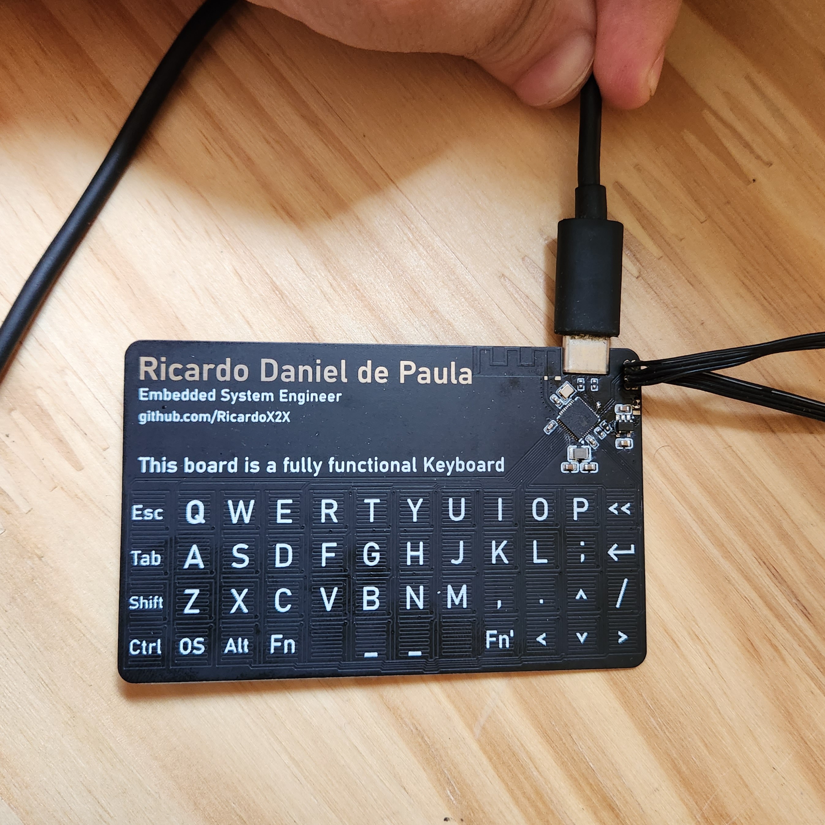
To facilitate debugging in this first version, I also soldered some wires to the programming connectors. This will make it easier to test and refine the firmware as I go. I’m happy to report that I’ve already managed to execute code on the microcontroller
But i will be making a dedicated post specifically about the firmware development process.
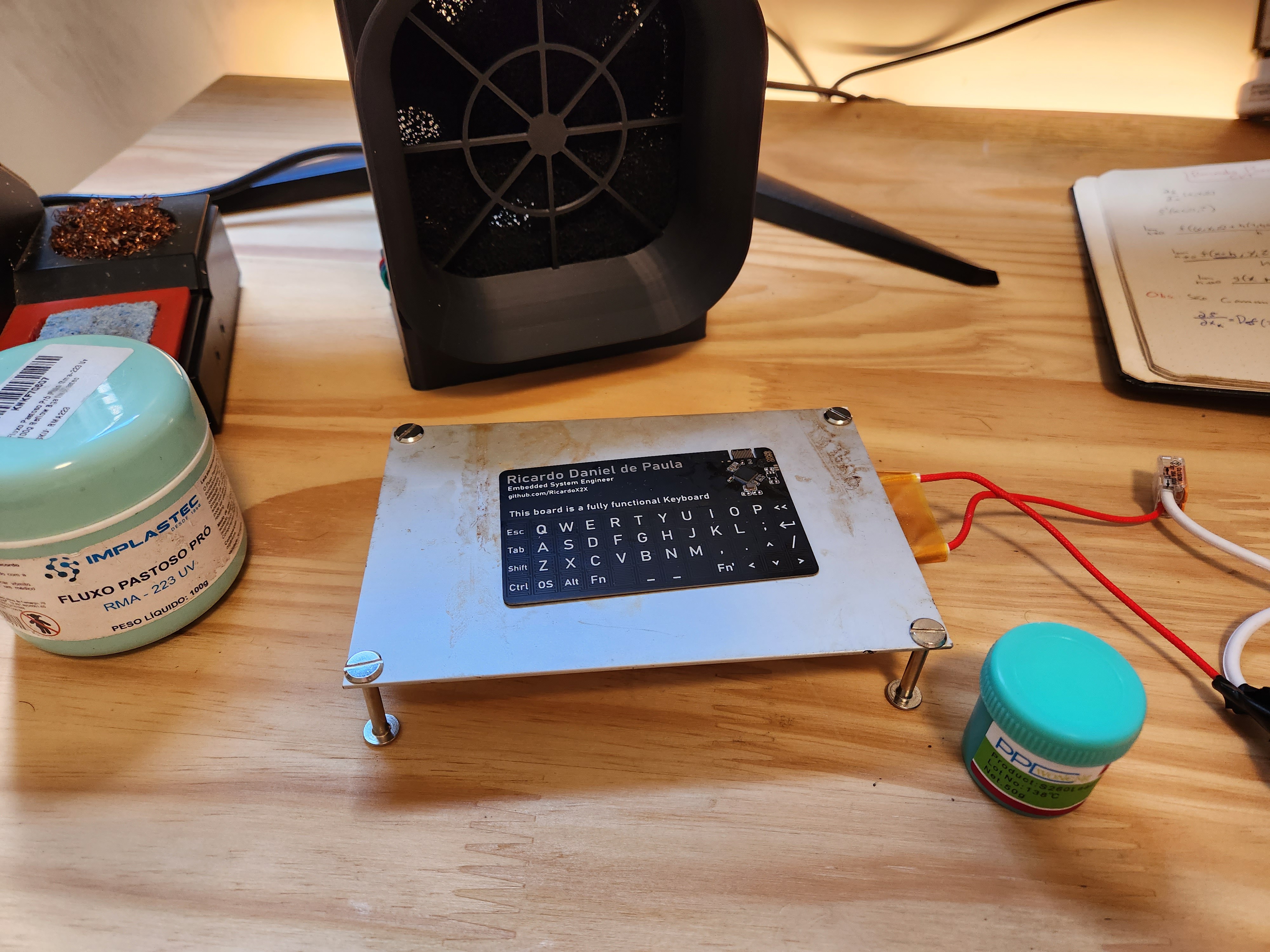
Fully assembled and soldered board ready for testing
Thank you all for your support and feedback! Stay tuned for more updates soon! 🚀
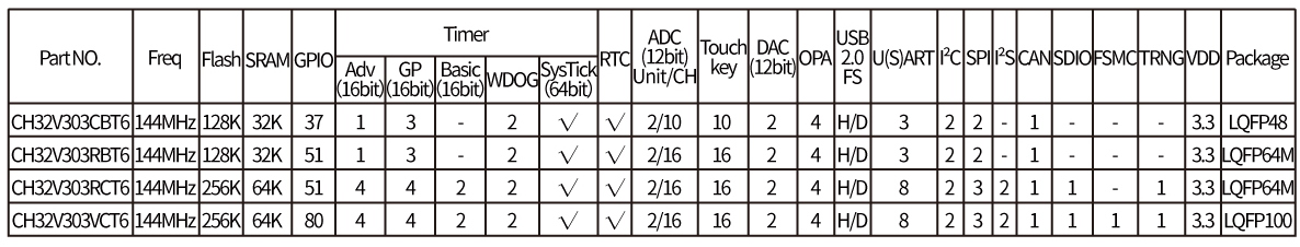
Well, last week after a lot of time spend in research i decide to use the CH32V303 microcontroller from the chinese manufacture WCH, mostly because it's price. but after read after read the documentation and start some PCB routing i discovered that CH32V303 has 4 versions [1}, 3 with 16 TouchKey pins and only one with 10:
And for the surprise of no one the version that i initially choose for this project was the one with only 10 touch capable pins, util there everything was "ok" i only had to pick the version with more pins... but checking the price it turns out the CH32V303RBT6 is at least 50% more expansive than CH32V303CBT6 in quantity:
I really wanna this project been cheaper as possible. So i had no other option than start to search for microcontrollers again. So i spend some hours looking for Silver.. than a i found Gold; The CH582M:
The chip not only have 14 touchKeys and USB support, but also have Bluetooth Low Energy module AND are in the same price of the CH32V303, so it is the perfect choice, and maybe it can add a feature that wasn't in my plans; wireless.
For now all i have is the ideia, a dream and some initial draws.
I initially started to thinking which microcontroller i will use for this project, and some easy ideias come to my mind, like the; RP2040, Atmega32u and STM32F103, all with USB interface Build-in and a vast community examples of how to use them like a keyboard, but after some research i found none of them has capacitive touch functionality, which is not exactly a problem, cause this functionality can be easily implemented by software, but with little bit of more research i discover the CH32V303, which accordingly to his datasheet have built-in USB2.0 and 16 channels of capacitive touch; with this i could multiplexing 12x4 touch pins and get a 48 keys, which is more than enough to consider this a 40% keyboard. The chip is very cheap (:D) and just need a few passive components to work well. So the CH32V303 was the first choice for this project, i hope the software development doesn't make me regret.
Other thing that i wanna for this project is a PCB usb-c connector where i get the ideia from here, this make the project cheaper and more easy to give away it to someone else, which is the propose of a business card, but i will talk more about costs later.
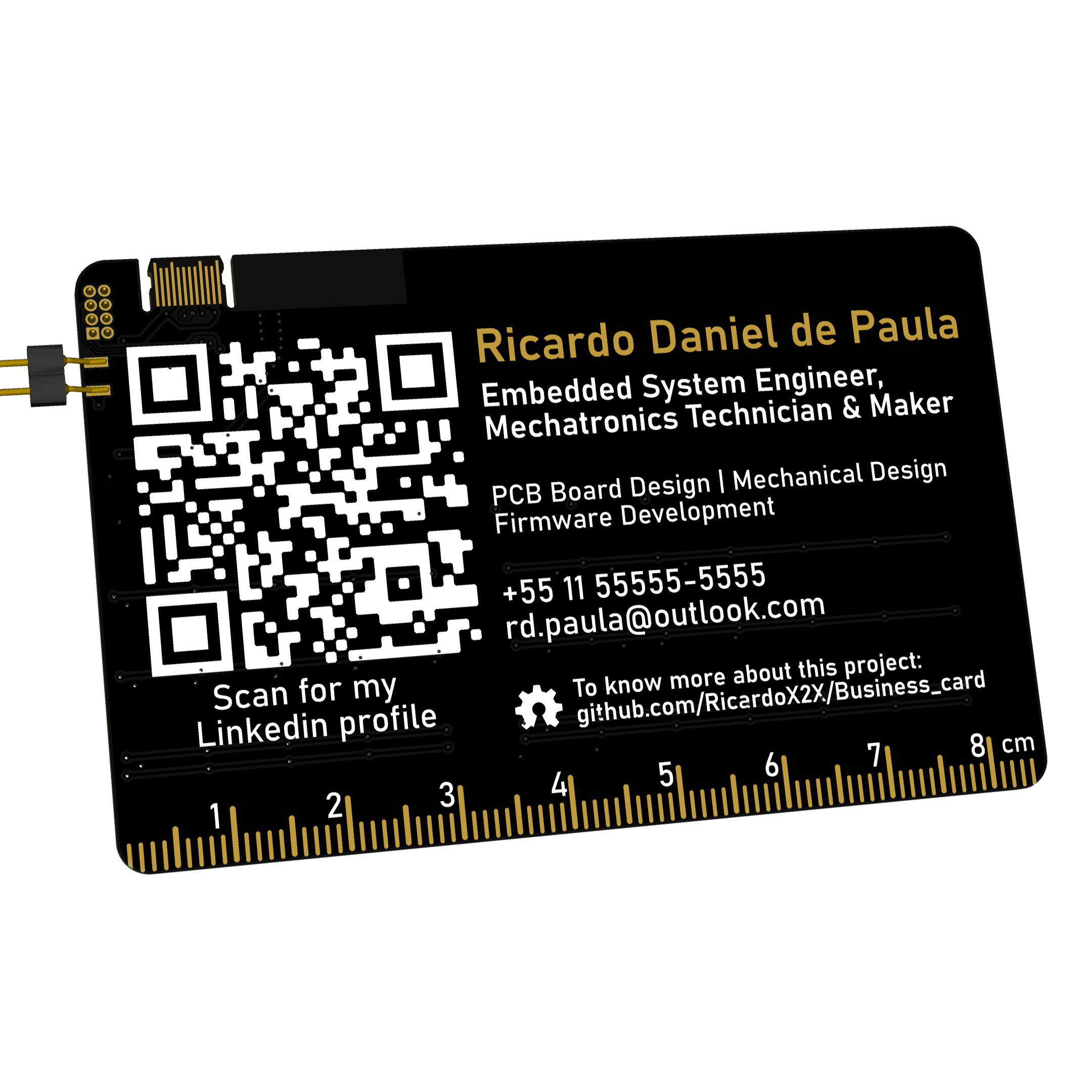
 Ricardo Daniel de Paula
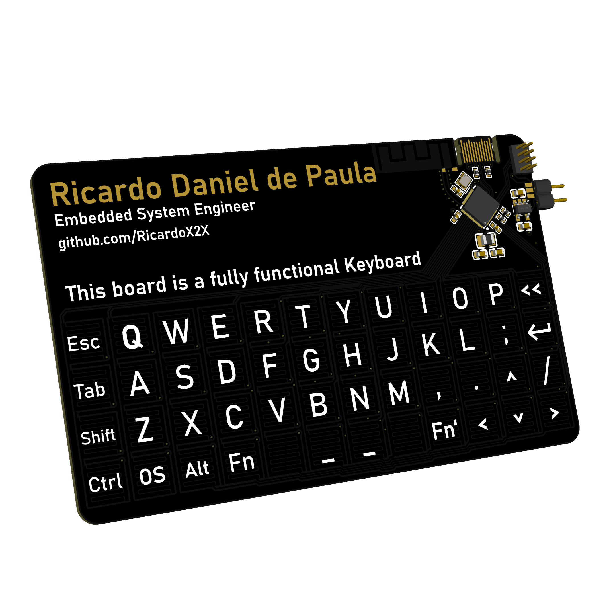
 Here's a close look at the antenna and main electronics:
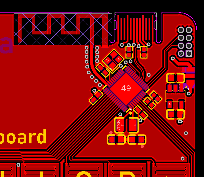


 The chip not only have 14 touchKeys and USB support, but also have Bluetooth Low Energy module AND are in the same price of the CH32V303, so it is the perfect choice, and maybe it can add a feature that wasn't in my plans; wireless.


