From the last blog, the electronics were connected to the finalized components such as the car’s 12 volt battery, steering wheel’s limit switches, and solenoids. Further progress has been made to the code as well, such as changing the shift sequence so the drivers don’t have to reach over when shifting from neutral to first gear while holding the clutch lever located in the cockpit’s left side. An additional improvement that was made, although not required, is giving the drivers the ability to shift into neutral from any gear. This will prevent the need to press the paddles multiple times as opposed to a single press of a dedicated button for this quick-action. Current electrical tasks involve replacing the Arduino jumper wires with the finalized solid-core wires.
Figure 1: Electronic components assembled
The pneumatic components have been nearly finalized. The air tank used is 80 cubic inches rated for 4500 PSI, the regulator used is custom adjustable output pressure from 0 - 250 PSI from Palmer’s Pursuit Shop, an on/off valve will be used for continuous airflow, the cylinder will be swapped for a larger bore size, and hoses were purchased. The current setup for the tank can be shown below:
Figure 2: Air Tank with On/Off Valve, Custom Regulator, and Hose output
Due to budget, a cheaper alternative was used for the 4/2 solenoid by using 3 3/2 solenoids on a rack. This can be seen below:
Figure 3: Solenoids Purchased
With these solenoids, one solenoid will control stroke A, another stroke B, and the third solenoid will control the piston's return to neutral position. Since these solenoids are rated for around 120 PSI as maximum working pressure, the larger bore-size piston is needed to prevent maxing out the solenoid. The old cylinder will be returned for a full refund and the additional air tank regulator will be as well. The air tank shield dimensions have been updated to 5” x 10” but the wall thickness and FEA is still pending because it needs to withstand the air tank exploding.
In the work period of February 15 to March 22, the team plans on finalizing purchases for any miscellaneous fittings required, working on validation plans for the project, and finishing the remaining fabrication. The fittings needed are reducers from the solenoid rack to the hose. As for validation plans, the pneumatic system and electronics will be tested soon, however, a high-pressure pump is still needed. This pump has been provided by a Cougar Racing team member but it needs a new filter to prevent it from pumping water into the air tank. Once this filter is obtained, experimental validation can be started to measure the force output by the cylinder. The remaining fabrication will be mounting tabs required to add parts to the FSAE chassis, the steering wheel, electronics housings, and air tank shield.
Some present electrical obstacles concern making the electrical connector for the quick release. This involves male and female ports being separated when the steering wheel is disconnected, allowing the wire harness to remain in the car. The electrical connector will be made up of 3D prints and copper pogo pins.
Additional obstacles in terms of pneumatics will be the high-pressure pump filter depending on the budget required. To resolve this, immediate action is needed to prevent any further delays. The air tank shield needs to be further developed and revised through FEA. A validation plan will need to be established however, it's likely to increase to a wall thickness that will be harder to test with.
Overall, the team needs to finish fabrication as soon as possible and begin to implement a validation plan for all components to meet our milestones.
For the work period of January 13 - February 1, what work toward your team's project has been completed? Please provide a description of tasks that are completed, as well as tasks currently in progress.
The team’s project progress from January 13th to February 1st has been the rework of the pneumatic components due to stock issues and changes in plans, paddle shifter iterations, and purchases of materials.
The pneumatic components were reworked to increase the volume of air and stock issues. Originally, the team wanted to use a ninja 68 cubic inch tank rated for 4500 PSI with a custom regulator outputting 120 PSI, however, this regulator went out of stock as it is very common for FSAE teams to use this. The component is also fabricated by a local shop with limited supplies, so it sold out quickly. To upgrade the volume, the 90 cubic inch tank rated for 4500 PSI was selected but it went out of stock as well (this can be seen below).
Figure 1: Regulator and Tank Sold Out
As an alternative to the 90 cubic inch tank, the team opted for a larger tank that is still available, therefore the 80 cubic inch tank from HK Army was purchased and was delivered on 1/31/2025. To regulate this pressure, the team will utilize the adjustable HK Army regulator rated at 250 to 300 PSI which was delivered on 1/31/2025. Because our working pressure is 120 PSI, another regulator is needed which will be purchased from McMaster Carr, it will be ordered alongside the 4/2 solenoid and hoses needed. The solenoid, hoses, and fittings needed for the pneumatic system are currently pending revision to guarantee proper fit in the system. This revision is necessary to minimize downtime usage later on by making sure parts are compatible and are the most economical.
Figure 2: Tank and Regulator Delivery (Tank guard given for free)
Additionally, the pneumatic cylinder has been purchased and delivered to confirm the solenoid needed as the specifications weren’t sufficiently detailed. Based on current findings, the cylinder has three inlets, one inlet actuates 0.5 inches of the cylinder extension, the second inlet actuates 1 inch of the cylinder extension, and the third inlet retracts the cylinder all the way. Considering this, we will need two simultaneous air flow directions at a given time. In our capstone project, the 0.5-inch stroke A will be used as the neutral starting position. Therefore to upshift, the pneumatic cylinder will need to actuate the 1-inch stroke B extension to engage the engine gear shifter to go up a gear, as soon as the gear is shifted, the cylinder will then instantly retract to the starting position. The programming will be essential for the cylinder to return to the neutral starting position here because the retraction inlet does not have a limit of retraction distance. This means that if we want to retract the cylinder following the 1-inch stroke B extension, upon airflow to the retraction inlet, the cylinder will retract completely to an extension of 0 inches which is an issue. The retraction inlet has no limit of retraction, so if we want to ensure the neutral starting position is at 0.5 inches, we will need the cylinder to retract back to a 0.5-inch extension or slightly further, then simultaneously allow airflow to the 0.5-inch extension. Essentially, the extension and retraction will need to be actuated in such a way that the cylinder retracts back to 0.5 inches of extension following the engine gear shifting. These conclusions were drawn based on the physical testing of the cylinder, a screenshot of this is shown below.
Figure 3: Pneumatic Cylinder Testing
Based on the testing, the 4 way two port solenoid is confirmed to be the necessary component needed to purchase (an example of this solenoid is provided below).
Figure 4: Sample 4/2 Solenoid
With this solenoid in mind, the programming of the arduino can be updated to address the flow ports correctly for initial testing in validation.
The HPA carbon fiber tank will require a shield to protect the driver and audience’s safety. This shield and the steering wheel will be manufactured with aluminum. The plan in capstone 1 was to use aluminum 6061, however, based on quote estimates and material availability, we may use aluminum 5052 instead. An additional change for the shield will be the update to the final design. Originally the shield was planned out to be a hollow rectangular prism to fully enclose the tank, however, that design uses an unnecessary amount of material increasing weight and material cost. The updated shield the team plans on making is shown below.
Figure 5: Updated Air Tank Shield
After driver input of the paddle shifter assembly, it has gone through another iteration and a rework of the overall mechanism. The previous assembly had an extremely tight engagement window as there was not a lot of resistance to activate the button. With the new iteration the button was switched out with a microswitch. It has more resistance so it is not prone to accidental activation and from driver’s feedback it is more tactile.
Moreover, the first physical prototype of the electronics was assembled after having been designed in Tinkercad, as shown in Figure 6. Missing components such as the solenoid and car battery have been considered in the design as well as the code and will be integrated once available.
To align with the shifting sequence of the current FSAE car (1-N-2-3-4-5-6), the code will need to begin in neutral otherwise the engine will stall upon startup. After that, the code will follow any input given by the driver if it’s downshifting into 1st or upshifting into 2nd and so on. Due to the engine that is used only having an “in-neutral” indicator and not a gear indicator, the code will need to splice into it to correlate when the car is in neutral to begin counting the shifts either up or down. This way of counting will serve as our gear indicator.
Figure 6: Starting in neutral gear
As previously mentioned, limit switches will be used for the downshifting/upshifting actions and a button switch for the neutral command. The neutral button will be located somewhere in the center of the steering wheel’s side facing the driver as shown in Figure 7 and Figure 8. The code has been made in that it will only allow the driver to press the neutral button if it reads that it is 1st gear. Pressing the neutral button in any other gear will be followed with an error command.
Additionally, the code will prevent the gear indicator from going below 1 or above 6, these being the lowest and highest gears in the car respectively. This is to prevent the pneumatic piston from being actuated accidentally and damage the engine gear shifter.
Figure 7: Left button for downshifting
Figure 8: Right button for upshifting
2. For the work period of February 1 - February 15 what is your team's plan for near term work? What major milestones does the team hope to achieve in your work?
Using the time between February 1st to February 15th, the pneumatic component purchase selection will be finalized and purchased, ideally delivered before the 12th to begin assembly and validation. The remaining needed components for the pneumatics are the solenoid, hose, fittings, second pressure regulator, insulation, and aluminum material. The major milestones desired to achieve with the components are initial testing and assembly, solenoid programming, and validation. The initial testing for the pneumatic components will mainly focus on the verification of component compatibility. For instance, the HK Army tank has a stock regulator, so installing the new regulator is needed as well as testing to ensure part functionality. In addition, because the pneumatics will need an open-air flow from the tank to the hose, an on/off valve has been purchased and delivered (the component is shown below). Using this component, once the tank and regulator arrive, initial testing of this is available to verify functionality.
Figure 9: On/Off Adapter for Tank
The validation to complete for the pneumatics is the force output of the cylinder, temperature changes from running engine measured directly from engine and insulation, failure stress of mounting tabs, and air leakage from the pressurized pneumatic system. As part of this work period, validation planning is necessary to stay on schedule.
The steering wheel material will be purchased on Monday February 3rd. A quote was obtained for 2 plates of 5052 3/16”, 11” x 6”. The change of material did cause a change in the calculated safety factor, but we will still obtain our goal of the steering wheel being over 1.33.
Figure 10: FEA Model of Steering Wheel and 5052 Aluminum Quote
The electronics assembly will be mounted with 3D printed steering wheel to confirm fitment as well as begin running the wire spool for exact wire length routed from the Arduino being placed near the cluster panel to the solenoid near the driver’s back.
3. What obstacles does the team foresee in your project work over the next two weeks? What solutions does the team have in mind and what back-up plans does the team have?
The obstacles foreseen in the next two weeks is the FSAE organization delays as the current car is being presented at different events so validation may be delayed. To use time efficiently, other validations that don’t require the car will be completed, for instance, the load cell validation of the pneumatic cylinder. Additionally obstacles foreseen is shipping times which could waste time further if parts aren’t ordered soon. This obstacle can only be amended by the team working in a timely manner on the capstone project.
4. Provide at least 3 figures to show the concrete progress and current status of the team's work. Please refrain from presenting your team's Gantt charts and from providing only photos of acquired materials with no further work.
Figure 11: Fabrication of Pins for Paddle Shifter (photo collage)
Due to the rework done for the paddle shifter a set of pins and bushings was needed. Through McMaster-Carr each pin was $11 and a set of bushings was around $2, to further limit the usage of our budget the pins were fabricated at Sulzer from stock material found at the FSAE shop. As the components are not critical the composition of the metal is not known, but with the new design the paddles have no play and have a firm tactile click when engaged.
As previously mentioned the material 5052 plates of aluminum are being ordered, the steering wheel design is finalized and all that is left is the fabrication of the steering wheel. In figure 11 a 3D printed prototype was made to test out the fitment of the assembly and to check for interference.
The team’s project progress from January 13th to February 1st has been the rework of the pneumatic components due to stock issues and changes in plans, paddle shifter improvement, and purchases of materials.
The pneumatic components were reworked to increase the volume of air and stock issues. Originally, the team wanted to use a ninja 68 cubic inch tank rated for 4500 PSI with a custom regulator outputting 120 PSI, however, this regulator went out of stock as it is very common for FSAE teams to use this. A local shop with limited supplies also fabricates the component, so it sold out quickly. To upgrade the volume, the 90 cubic inch tank rated for 4500 PSI was selected but it went out of stock as well (this can be seen below).
Figure 1: Regulator and Tank Sold Out
As an alternative to the 90 cubic inch tank, the team opted for a larger tank that is still available, therefore the 80 cubic inch tank from HK Army was purchased and was delivered on 1/31/2025. To regulate this pressure, the team will utilize the adjustable HK Army regulator rated at 250 to 300 PSI which was delivered on 1/31/2025. Because our working pressure is 120 PSI, another regulator is needed which will be purchased from McMaster Carr, it will be ordered alongside the 4/2 solenoid and hoses needed. The solenoid, hoses, and fittings needed for the pneumatic system are currently pending revision to guarantee proper fit in the system. This revision is necessary to minimize downtime usage later on by making sure parts are compatible and are the most economical.
Figure 2: Tank and Regulator Delivery (Tank guard given for free)
Additionally, the pneumatic cylinder has been purchased and delivered to confirm the solenoid needed as the specifications weren’t sufficiently detailed. Based on current findings, the cylinder has three inlets, one inlet actuates 0.5 inches of the cylinder extension, the second inlet actuates 1 inch of the cylinder extension, and the third inlet retracts the cylinder all the way. Considering this, we will need two simultaneous air flow directions at a given time. In our capstone project, the 0.5-inch stroke A will be used as the neutral starting position. Therefore to upshift, the pneumatic cylinder will need to actuate the 1-inch stroke B extension to engage the engine gear shifter to go up a gear, as soon as the gear is shifted, the cylinder will then instantly retract to the starting position. The programming will be essential for the cylinder to return to the neutral starting position here because the retraction inlet does not have a limit of retraction distance. This means that if we want to retract the cylinder following the 1-inch stroke B extension, upon airflow to the retraction inlet, the cylinder will retract completely to an extension of 0 inches which is an issue. The retraction inlet has no limit of retraction, so if we want to ensure the neutral starting position is at 0.5 inches, we will need the cylinder to retract back to a 0.5-inch extension or slightly further, then simultaneously allow airflow to the 0.5-inch extension. Essentially, the extension and retraction will need to be actuated in such a way that the cylinder retracts back to 0.5 inches of extension following the engine gear shifting. These conclusions were drawn based on the physical testing of the cylinder, a screenshot of this is shown below.
Figure 3: Pneumatic Cylinder Testing
Based on the testing, the 4 way two-port solenoid is confirmed to be the necessary component needed to purchase (an example of this solenoid is provided below).
Figure 4: Sample 4/2 Solenoid
With this solenoid in mind, the programming of the Arduino can be updated to address the flow ports correctly for initial testing in validation.
The HPA carbon fiber tank will require a shield to protect the driver and audience’s safety. This shield and the steering wheel will be manufactured with aluminum. The plan in capstone 1 was to use aluminum 6061, however, based on quote estimates and material availability, we may use aluminum 5052 instead. An additional change for the shield will be the update to the final design. Originally the shield was planned out to be a hollow rectangular prism to fully enclose the tank, however, that design uses an unnecessary amount of material increasing weight and material cost. The updated shield the team plans on making is shown below.
Figure 5: Updated Air Tank Shield
Using the time between February 1st to February 15th, the pneumatic component purchase selection will be finalized and purchased, ideally delivered before the 12th to begin assembly and validation. The remaining needed components for the pneumatics are the solenoid, hose, fittings, second pressure regulator, insulation, and aluminum material. The major milestones desired to achieve with the components are initial testing and assembly, solenoid programming, and validation. The initial testing for the pneumatic components will mainly focus on the verification of component compatibility. For instance, the HK Army tank has a stock regulator, so installing the new regulator is needed as well as testing to ensure part functionality. In addition, because the pneumatics will need an open-air flow from the tank to the hose, an on/off valve has been purchased and delivered (the component is shown below). Using this component, once the tank and regulator arrive, initial testing of this is available to verify functionality.
Figure 6: On/Off Adapter for Tank
The validation to complete for the pneumatics is the force output of the cylinder, temperature changes from running engine measured directly from engine and insulation, failure stress of mounting tabs, and air leakage from the pressurized pneumatic system. As part of this work period, validation planning is necessary to stay on schedule.
In the work period of November 9th to November 23rd, we had the goals to finalize the CAD design of the steering wheel with paddle shifters, selecting the pneumatic components, conducting thermal analysis for insulation on the pneumatics, designing the electrical system, and developing the Arduino program.The steering wheel has gone through design revisions as feedback was obtained from Cougar Racing drivers and FEA models. A Design Matrix was created to compare 4 different versions of the steering wheel (figure 1); the numbers were determined from the drivers themselves and from our input.
Figure 1: Decision Matrix
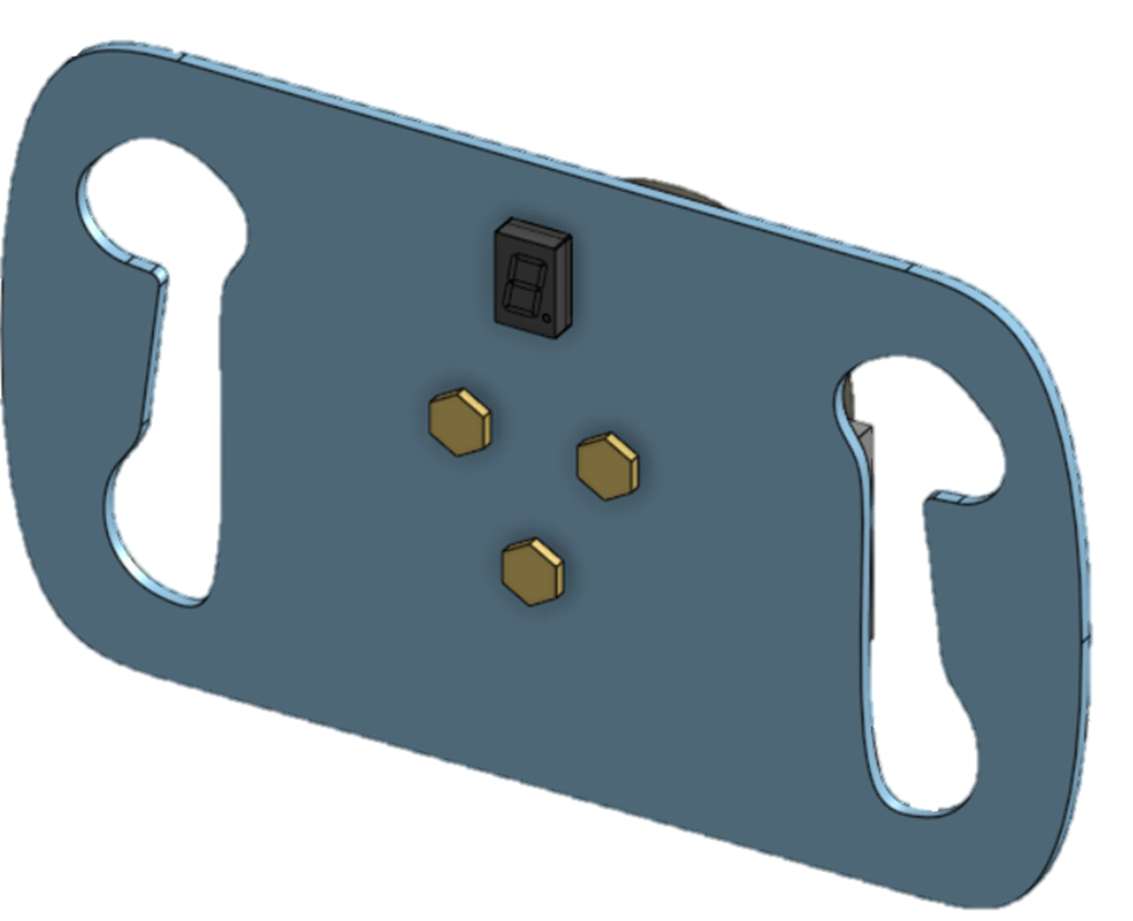
Versions 1-3 were different wheel designs, though had the same width and handle geometry. After a meeting with the drivers and the Machine Man Interface leads they recommend a wider steering wheel and bigger handles for comfort. This has led to the creation of the 4th version after optimization to achieve a higher safety factor while reducing the overall steering wheel thickness down to 0.25” as version 3 was 0.375” thick. Figure xx shows the difference between version 3 & 4, respectively. Figure 2: Steering Wheel Design Changes
Version 4 has markings on the steering wheel, they represent the placement of the drivers hands when they’re at their most natural position. This was considered in the CAD as it changes the geometry of the paddles.
The progress for pneumatic components complete was the creation of the pneumatic system components with options for the cylinder, solenoid, pressure regulator, and tubing. In addition, specifications for these components are needed have been selected using a tabulation of scores with comparisons. This portion has been completed through selection of criteria that are important and will ensure an efficient result.
The pneumatic components progress has tasks that have been completed and are still in progress.
The completed portion of the pneumatic component tasks is the tabulation of comparison between specifications on the air tank, pneumatic cylinders, and bore size determination. Based on this, a compilation of components from a seller is put together for the pneumatic cylinder, solenoid, pressure regulator for the air tank, pressure regulator to further decrease pressure, hoses, and insulation from the heat was created. The first tabulation was for the bore diameter which will affect the working pressure required to be regulated and the cubic inches per minute of compressed air needed. For the tabulation, there are options set with descriptions to identify what specifications the options were created with, exact values for criteria scored, criteria weights, criteria scores for options, and totals. In this tabulation, a higher score means a worse result, so the lowest number means it's the most efficient for our design. Option 0 was made with the maximum score possible, otherwise the worst score possible. The tabulation of the bore diameter results are below: Figure 3: Tabulation for Bore Diameter Selection
Based on the tabulation, the ideal bore diameter will be 0.75” as it makes effective use of its working pressure to output 50 lbf with a relatively low volume of compressed air needed for 100 shifts. With the bore diameter determined, we can put together a system of components focusing on the 0.75” bore diameter, however in case of limited options, the system will have the next best option as well, in this case, due to limited availability of cylinders, 1.0625” bore diameter has been selected. To select the best pneumatic cylinder for a system, we have the choice of one multi-stroke cylinder or two single acting cylinders to perform the upshift and downshifts. The multi-stroke cylinder will take up less volume and will be a simpler mount, so a larger set of options was made for the multi-stroke cylinder. The selection of the pneumatic cylinder is based on the following tabulation:
Figure 4: Tabulation for Pneumatic Cylinder Selection
From the options created, the best choice is the 0.75” bore diameter multi-stroke cylinder based on cost, volume of the component and air, and hoses required. The cost itself is to be within budget, and the hoses quantity will cause problems in cable management due to lack of space available in the engine bay. Finally, the last tabulation for the pneumatics is for the air tank. The hoses, pressure regulator, and solenoid were selected based on compatibility, required specifications, and safety. For example, one compatibility feature is based on threading for the hoses to fit onto the cylinder. The required specifications are based on components, for instance, the air tank’s default pressure regulator outputs at 500 PSI, so we need another regulator to decrease it to 300 PSI, the easiest way to do this is using the air tank manufacturer’s adjustable regulator that will output at 300 PSI. From there, the pressure regulator needed is one that is rated to intake 300 PSI. As for safety, desired safety features for components are desired as heat will cause the pressure to increase, so we will have insulation to prevent this and in addition, safety features such as a relieving valve on the pressure regulator will be included. Therefore, the air tank will need a tabulation score to be selected which can be found below:
Figure 5: Tabulation for Air Tank Selection
Based on the score, the best choice will be the 68/4500 air tank as it makes the most effective use of volume with the maximum pressure. The 90/4500 air tank is still a valid option though as it can be used at a lower pressure for safety and contains sufficient volume for compressed air required for 30 minutes of use.
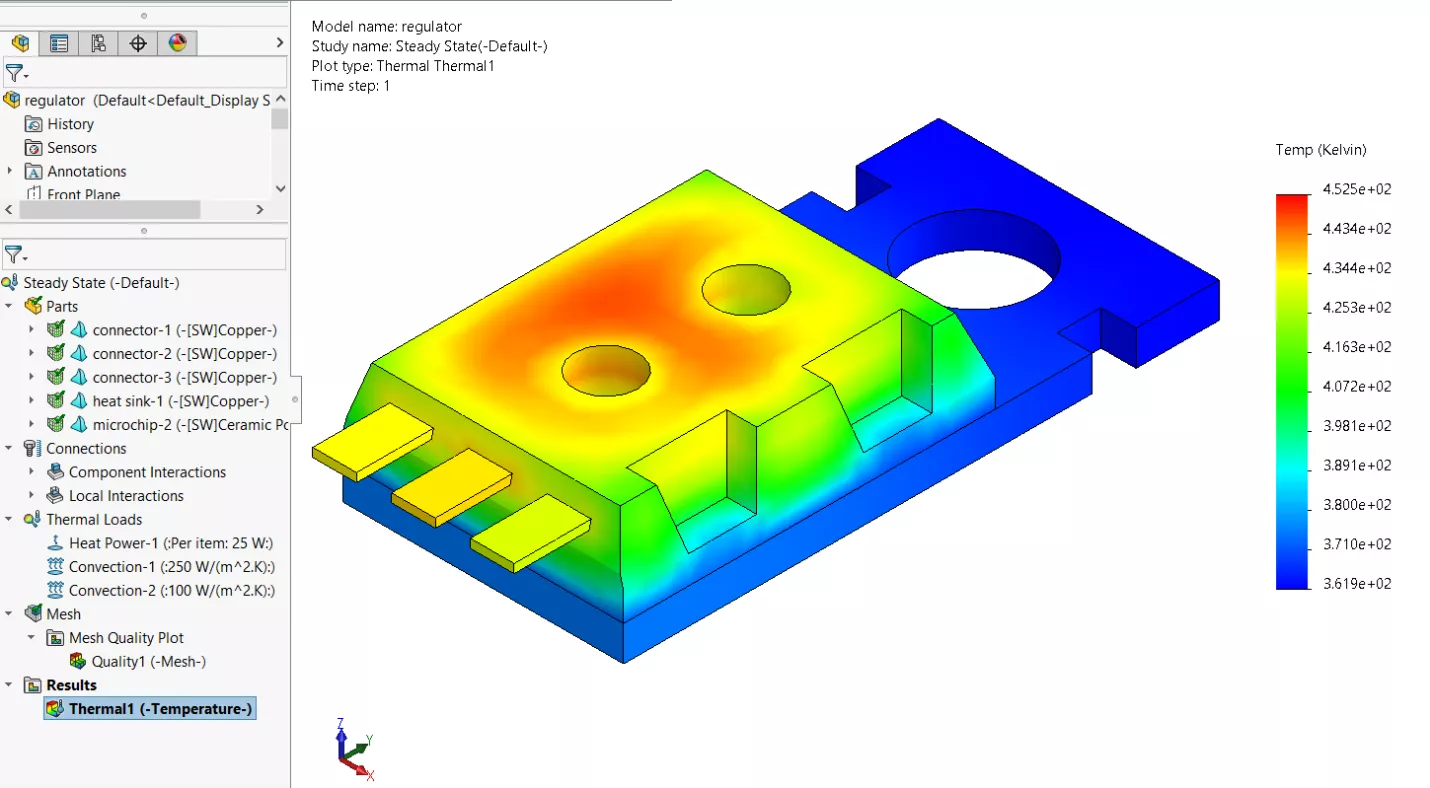
The tasks in progress for the pneumatic component is the thermal studies modeling, however, currently some heat transfer calculations were made to determine the conditions. Using a heat conduction model of the engine with the conduction coefficient of mild steel, we can estimate the heat transfer to air which is around 83 ℃ or around 392 ℉. Based on this value, insulation can be chosen that is rated to withstand more than the heat transferred to the air. Although the thermal study model can help, knowing the temperature the air will be at is more useful to estimate the specifications needed for insulation. Therefore, silicone rubber filled with fiberglass will be used as insulation material for pneumatic components which is rated at a working temperature of 500 ℉.
For the electrical system, we were able to develop an initial design with the use of Tinkercad, allowing us to get a preview of what electrical components the project will be requiring. In Figure 6, the 12 V battery provided by the car will power the solenoids. Since the Arduino can only provide 40 mA at 5 V to its pins, transistors (TIP120) will allow for the Arduino to handle the higher electrical loads from the 12 V battery. Two switches integrated into the steering wheel will dictate the downshift and upshift functions.
Figure 6: Arduino Sample Circuit
Additionally, we developed an initial iteration of the Arduino code. During the writing process, failsafes came to mind that will prevent damage to components from the pneumatic system or inside the engine if the driver were to ever accidentally initiate a shift while the engine’s revolutions per minute (RPM) were not at an adequate range to do so.
Our final design focuses on a comprehensive paddle-shifting system that addresses key challenges in performance, integration, and driver ergonomics. The design is divided into three sub-systems: pneumatics, electronics, and the steering wheel.
The pneumatics sub-system includes a 3-position piston to engage the engine clutch lever, a 68 in³ air tank to sustain system operation for at least 30 minutes, and solenoids controlled by the electrical system to actuate the piston. This ensures reliable and precise shifting over extended periods.
The electronics sub-system is powered by an Arduino that collects data from the tachometer and the driver's input via buttons. Custom code processes this information to validate shifts and prevent user errors that could damage the engine, ensuring both functionality and safety.
Lastly, the steering wheel sub-system was entirely redesigned to integrate paddle shifters effectively. Retrofitting the existing wheel proved impractical due to limited space, so we fabricated a new wheel that accommodates the necessary electronics while improving driver ergonomics. This approach prioritizes comfort and usability, shifting the focus from merely "steering the car" to truly "accommodating the driver."
Overall, this design resolves the identified issues by delivering a seamless, ergonomic, and reliable paddle-shifting system.
The key analytical results at this stage highlight the successes and strengths of our design, particularly in the steering wheel and pneumatic systems.
Steering Wheel Analysis
The analytical results for the steering wheel were obtained through FEA (Finite Element Analysis), which provided the safety factor of the new design. This ensures the wheel meets structural integrity requirements while accommodating the integration of paddle shifters and improving driver ergonomics.
Figure 7: FEA Results
Figure 8: FEA Simulation Model
Pneumatics Analysis
The pneumatic system's design is supported by detailed parameter analysis, including pressure, compressed air volume, flow rate, temperature, geometry, and heat transfer.
Air Tank Selection: A 68 cubic inch air tank, rated for a maximum pressure of 4500 PSI, was selected. It includes a built-in pressure regulator outputting at 500 PSI. Due to the availability of low-pressure regulators with limits between 300-400 PSI, an additional adjustable pressure regulator will be purchased from Ninja (the air tank manufacturer) to step down pressure to 300 PSI. This is further regulated to a range of 50-125 PSI, ensuring modularity for various operations.
Component Specifications: The solenoids and hoses were selected to match the system's 50-125 PSI range. Calculations confirmed compatibility and operational safety.
Pressure and Force Calculations: Using force/area (F/A) calculations based on the piston area, the working pressure required to generate 50 lbf was determined. Geometry calculations, using the similarity of triangles and the Pythagorean theorem, determined the piston’s minimum stroke length to be 0.6478 inches.
Compressed Air Volume and Capacity: Using a single-stroke cylinder model, the compressed air volume needed for optimal operation was estimated. At working pressure, the volume is approximately 795.22 cubic inches, or 20.322 cubic inches at 4500 PSI. For 30 minutes of operation at 60 shifts per minute, the 68 cubic inch air tank provides sufficient capacity to supply the pneumatic components.
Heat Transfer and Insulation: Engine heat transfer is estimated to raise the air temperature to 84.73℃. Insulation will be necessary to prevent overheating, which could lead to increased working pressure and potential system instability.
Flow Rate and Activation Time: Using Bernoulli’s equation and pressure differences from the regulators to the hose, the estimated fill time for one foot of hose at 115 PSI is approximately 0.001 seconds. This supports achieving the desired 0.4-second activation time from paddle input to engine gear shift actuation.
These results demonstrate the reliability, efficiency, and safety of our design. They validate that the system can handle operational demands, meets performance criteria, and provides flexibility for future improvements.
Looking ahead to Capstone II, our team has outlined several key preparations to ensure we are ready to execute our design by the start of the Spring 2025 semester.
Steering Wheel Preparations
We will coordinate with Sulzer to finalize access to their large CNC machine, identifying an appropriate time frame that avoids interfering with their business operations. Using Inventor’s CAM (Computer-Aided Manufacturing) add-on, we will generate the necessary G-code for manufacturing the aluminum steering wheel. To minimize material waste, we plan to create test pieces from scrap metal or wood before ordering the 6061 aluminum stock. This approach ensures precision and reduces potential delays.
Pneumatics Preparations
For the pneumatic system, we have preselected components, but availability will need to be confirmed with suppliers before the Spring semester begins. Additionally, we will finalize the mounting points for key components, including the air tank, pneumatic cylinder, solenoid, and pressure regulator.
Collaboration and Integration
Close collaboration with the UH FSAE team will be crucial to ensure all subteam components are well-organized and that the pneumatic components are efficiently integrated into the overall system. This teamwork will streamline the mounting process and address potential conflicts early.
By completing these preparations, our team will enter Capstone II equipped to execute the design smoothly and effectively.
As we are nearing the end of the semester, an update is needed regarding how we used our time from October 27 up until now. Within October 27 and November 9 an iteration of the steering wheel was designed. Inspiration came from an already made steering wheel by FBS Racing Team [Figure 1], their steering wheel has been designed to be as low profile and lightweight as possible. Our design is a heavily modified version that allows space for the attachment of the paddle shifters and a 7 segment display to indicate the gear the car is currently on. The steering wheel is currently being printed to obtain feedback from the Cougar Racing drivers, and to begin to create molds for the grips through the usage of clay and a 3d scanner.
Figure 1: Steering Wheel Sample
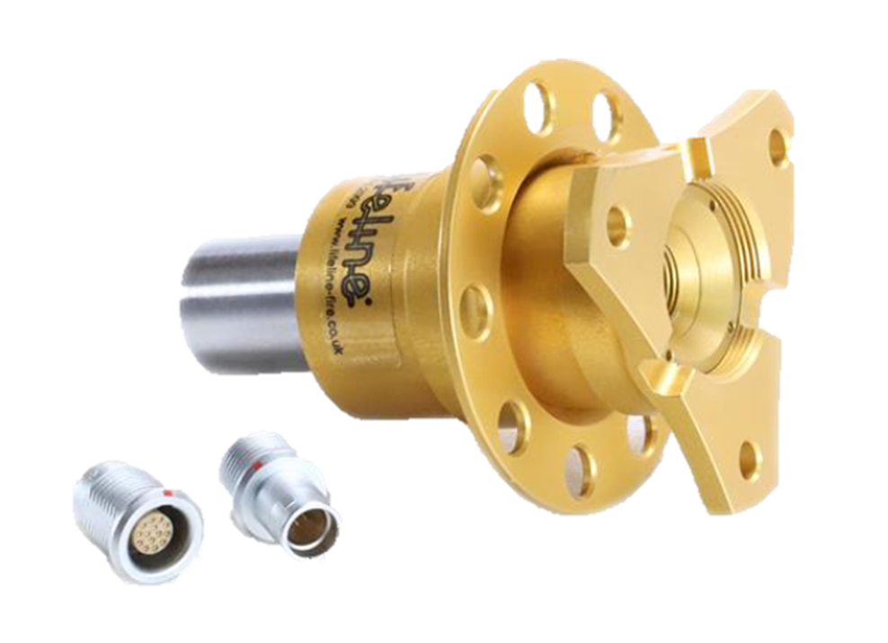
We’ve also researched quick-release kits that have integrated data pins for electronic signals [Figure 3]. 3 data wires are running from an Arduino towards the steering wheel: 2 wires for buttons that are actuated by the paddle shifters and 1 for the gear indicator.
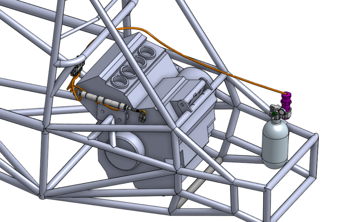
As the piston and pneumatic components are selected, they are being derived onto the Cougar Racing master CAD to explore different placements and start designing mounts for the pneumatic components. [Figure 2]
Figure 2: Pneumatic Components Near Engine
Figure 3: Quick Disconnect for Steering Wheel
To be on track with our capstone and project deadlines, for the work period from November 9th to November 23rd, the team’s plan focuses on finalizing several key design elements following technical analyses. The plan we will work toward is the following:
Finalizing the CAD Design of the Steering Wheel with Paddle Shifters: We will complete the CAD model for the steering wheel with paddles. This design will be inspired by previous designs but refined through FEA (Finite Element Analysis) in COMSOL or SOLIDWORKS to simulate real-world conditions. Based on FEA results, adjustments will be made to optimize safety factors, including modifying the aluminum thickness and selecting an appropriate grade based on the anticipated radial forces. We will also identify stress points and adjust wall thickness and paddle shape accordingly. Our target is to finalize the CAD and complete the FEA review for this assembly within the November 9th to November 23rd timeframe.
Selecting Pneumatic Components: The team will evaluate various pneumatic system options to meet performance and cost requirements. With known constraints, such as the force output, total air tank volume, and maximum tank pressure, we will create 3 to 5 system configurations that include a three-position cylinder, solenoid valve, pressure regulator, and tubing. These configurations will be compared based on working pressure, price, volume, and weight, along with an estimate of operational efficiency for at least 60 shifts per minute. By November 16th, we plan to have a finalized selection based on these criteria in a tabulated point system.
Conducting Thermal Analysis and Insulation Selection: As part of the design process, we will perform a thermal analysis for insulation near the engine area. This analysis will determine the most effective insulation material to manage heat dissipation. By November 23rd, we expect to finalize the insulation choice based on this thermal analysis.
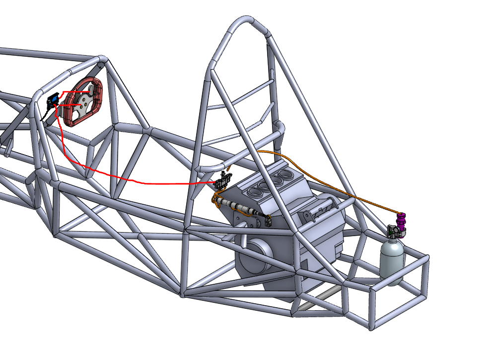
By the end of this work period, our deliverables will include a finalized CAD model for the steering wheel with FEA validation, a selected set of pneumatic components that meet our project constraints, and an insulation material chosen with a cost estimate based on thermal analysis. We will also initiate the programming for an Arduino to activate a solenoid valve as part of the pneumatic system. To provide a better understanding on the proposed system to put together by the end of November, see the figure below.
Figure 4: Sample Project Assembly (in progress)
For the work period from November 9th to November 23rd, the team anticipates encountering obstacles related to integrating pneumatic components with the existing FSAE components. Specifically, mounting placements for the pneumatic cylinder, solenoid, and air tank may be challenging due to limited space and FSAE rulebook requirements. To address these issues, close collaboration with the Cougar Racing powertrain team is crucial, as we need to navigate wire routing near the engine gear shifter and clutch. This collaboration will influence the selection and orientation of the pneumatic cylinder.
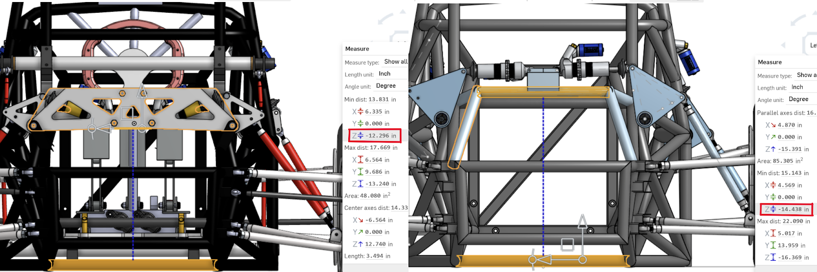
Another anticipated obstacle is finding a legal placement for the air tank, which currently lacks an approved location. We plan to discuss options with the chassis team, which may involve relocating differential tab mounts, and with the suspension team, which is redesigning the current suspension bridge which can be seen in Figure 5. These adjustments should enable the air tank to be placed safely away from engine heat while remaining within the chassis boundaries as mandated by FSAE rules.
Currently, the car’s engine is undergoing servicing and is expected to be operational by November 17th. Meanwhile, we are coordinating with the powertrain team on potentially running the engine outside the car to collect essential engine data, such as crankshaft position sensor readings and gear position sensor data.
Figure 5: Distance between bottom of the chassis to current suspension bridge (left) vs. proposed future design (right)
As mentioned previously, the paddle shifter project was developed to improve the competitiveness of the UH FSAE car in the SAE competition. With greater control of the vehicle, the driver can focus better on the track during autocross to improve their lap times instead of constantly shifting with a lever. This improvement was applied by Ferrari's Formula 1 team in 1989 which began the paddle shifter standard in F1 racing [1]. In modern F1 cars, paddle shifters are integrated into the steering wheel, and the paddles themselves, when sold separately, cost more than $700.
Figure 1: $700+ Ferrari F8 Paddles for Paddle Shifter
For university FSAE teams competing in the annual SAE competition, the cost of paddle shifters is impractical from both a competition and budget perspective. The SAE competition evaluates teams not only on dynamic events such as autocross and acceleration but also on a business presentation, which includes the cost to manufacture the car. While paddle shifters can offer a competitive advantage, they must be implemented affordably without sacrificing performance.
For the UH FSAE team, the paddle shifters will be paired with a pneumatic system that controls upshifting and downshifting. When the shifter is activated, electronic components will monitor engine RPMs to ensure shifts occur at safe levels. Once the correct RPM is reached, the pneumatic system will apply pressure to pistons that initiate the gear shift, repeating this process for each gear change. Additionally, the paddle shifters must be integrated around pre-existing components and operate while the engine is running, presenting critical physical constraints to consider.
The entire system, which includes the paddles, electronics, and pneumatic components, must not exceed a maximum weight of 50 lbs to avoid increasing the weight-to-horsepower ratio. The paddles themselves need to withstand a force of 121.1 kg, which represents the grip strength of the 95th percentile of men aged 20-24, as required by the FSAE rulebook. To account for safety, the paddles will be designed to handle 20% more than this force.
Additionally, the paddles must be positioned at least 24.88 inches from the driver to ensure accessibility for the 5th percentile of women in both upright and reclined driving positions. Paddle shifting time is expected to be 0.4 seconds, based on testing during vehicle operation on track. The system must also allow for easy attachment and detachment within 10 seconds for maintenance or replacement.
The system's power usage is still to be determined, as it must align with the vehicle's limited power from the stator, and the available space for the paddle shifters on the steering wheel is restricted to 126 cubic inches (9" x 7" x 2"). The total budget for the system is capped at $900, though efforts will be made to reduce costs where possible. In addition, the force required to move the lever and shift the engine's gears remains to be determined, and the system must be designed to withstand engine-convected heat of up to 210°C, ensuring the reliability of both the pneumatic and electronic components in such conditions.
Constraint
Value
Comments
Maximum Weight of the entire system
50 lbs
The system includes paddles, electronics, pneumatic components
Maximum Applied Force Paddles Can Withstand
121.1 kg * 1.2
The grip strength of the 95th percentile of men aged 20-24 is 121.1 kg, per the FSAE rulebook it must accommodate
Minimum Force Required to Activate Paddles
TBD
Minimum distance of Paddles from the driver in the upright or reclined position
24.88 inches
For the paddles to be within reach for the 5th percentile of women in a functional grip position
Paddle Shifting Time
0.4 seconds
Measured by recording the driver operating the vehicle in a track
Time for paddles to attach/detach
10 seconds
System Power Usage
TBD Watts
Vehicle limited in power by stator, need to verify the extra power available
Paddle Shifters Available Space
126 in^3; 9" x 7" x 2"
Volume/Dimensions available for paddles on steering wheel
System Cost
$900
Total budget available, want to reduce price as much as possible
Force required to move lever to change gears on engine
TBD
Need to know force required to be able to shift the gear on the engine
Expected temperature convected by the engine
210 °C
Pneumatics and electronics will be affected by the convected heat transfer
To address the key physical challenges before executing the design, we will rely on simulations and calculations. To determine the external forces our paddles can withstand, we can use software like SolidWorks or COMSOL to simulate constraints such as mounting points, material weight, and forces. This will allow us to generate a Von Mises diagram, identifying areas of our design experiencing the highest stress. A crucial aspect of this analysis is applying realistic constraints to the CAD model to accurately replicate the real-world conditions the system will face. Based on the results, we can make CAD model alterations to prevent high-stress concentration areas, identify effective material choices, and improve factors of safety.
Figure 2: Sample Von Mises Diagram
Additionally, thermal analysis will be conducted on the pneumatic components to assess the impact of engine heat on flow rate, pressure, and structural integrity. These simulations will help us anticipate how the system will perform in real-world conditions. Based on this result, we can identify areas that will have the greatest heat transfer to know where insulation could be needed.
To further validate our simulations, we can calculate the force required to move the engine's shifter based on available dimensions. From there, we can determine the pressure needed for the pneumatic pistons, optimizing the cross-sectional area for efficiency. Additional calculations will be made to insulate wiring and pneumatics from engine heat, helping us choose the optimal insulator thickness to minimize heat transfer.
Figure 3: Thermal Study Using SolidWorks
Additional challenges in the design include determining the exact mechanism that will use the pneumatic pistons to actuate the shifter on the engine for upshifting and downshifting. This will likely require a separate CAD design to specify how the pistons will interact with the shifter lever. Since the pistons will be located behind the engine, the available volume will be constrained by the chassis and powertrain components, further complicating the design.
Other important considerations include the method for mounting each component in its respective location: the pneumatic pistons to the chassis and shifting lever, the paddles to the steering wheel, and the electronics to the vehicle. Additionally, since we are using pneumatics, we must account for the inclusion of a compressor and air tank reservoir. These will introduce additional weight, cost, power requirements, volume constraints, and the need for mounting points.
Measuring a successful outcome will begin by verifying, outside of the car, that the paddles, electronics, and pneumatic system function properly for both upshifting and downshifting. Once we confirm that the programming works as intended and the compressor fills the tank reservoir to activate the pistons, we can then validate the simulated forces and calculations using the prototype.
The University of Houston hosts the Cougar Racing team, a student-led racing team abiding the Formula Society of Automotive Engineers’ (FSAE) rules. The nature of a racing team is to continuously be innovating to get ahead of the competition, while “simple is better” has created a solid foundation, improvement of a team requires change. A motorcycle engine is the beating heart of the current Cougar Racing team’s powertrain system, as it is a common trend for those engines to be retro-fitted into FSAE race cars. This approach comes with the benefit that the transmission and engine come built-in together. FSAE teams thus have to design a pedal box that actuates the throttle cable and implement a shifting lever to cycle through the transmission’s gears. Cougar Racing has been using a shifting lever, which requires the driver to take one of their hands off the steering wheel and engage the clutch pedal every time they need to cycle through the gears. This process distracts drivers as they are diverting their focus from a race. If a system can take control of the shifting lever and clutch pedal, this allows the driver to focus on the course which leads to faster lap times.
Sample CAD of Paddle Shifters to be placed behind steering wheel
Our teams approach is to create a paddle shifting system that eliminates the need of a clutch and shifter lever, while keeping the driver’s hands on the steering wheel at all times and reducing the shifting time by 50%. High performance teams have adopted this system into their race cars and became an industry standard (for drivers to focus more on driving). A footprint constrain of 9″ x 7″ x 2″ is considered with the paddle shifters needing to sit behind the steering wheel. The system will be paired with an onboard computer that can read engine data, specifically, the motor rpm, current gear, & wheel speed. As the computer takes in data, it can rapidly change gears with a click on the paddle shifters. A set of pistons would engage the clutch lever and shifting lever which is controlled by the onboard computer through solenoids.
CAD of the Main Assembly of 2024-25 Competition Car
With the goal of creating paddle shifters for FSAE, we expect to work around premade hardware which adds difficulty in our design phase. Through in-person data gathering, we will be able to gather dimensions, constraints, and expect the adjustments to made in our early design stages. In the development of the paddle shifters, we will keep in mind how the mechanical components fit onto the pre-existing vehicle, but we must also must consider the environment the components. Considering the parts will be on a functioning car, they must be able to withstand external forces as the car accelerates and decelerates, as well as the heat generated by the engine. If our components are near the engine, an analysis must be done to identify the heat’s effect on our design. Additionally, because the paddle shifters are expected to give a significant competitive advantage, they must have the longevity to be reused in future FSAE cars and abide by the FSAE rule book.
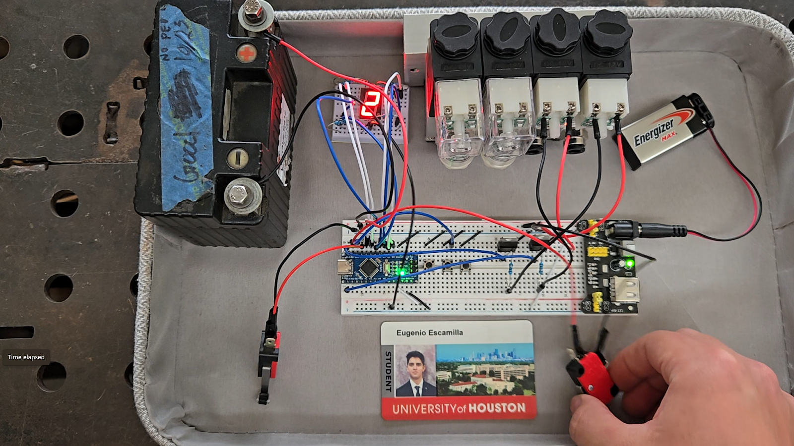
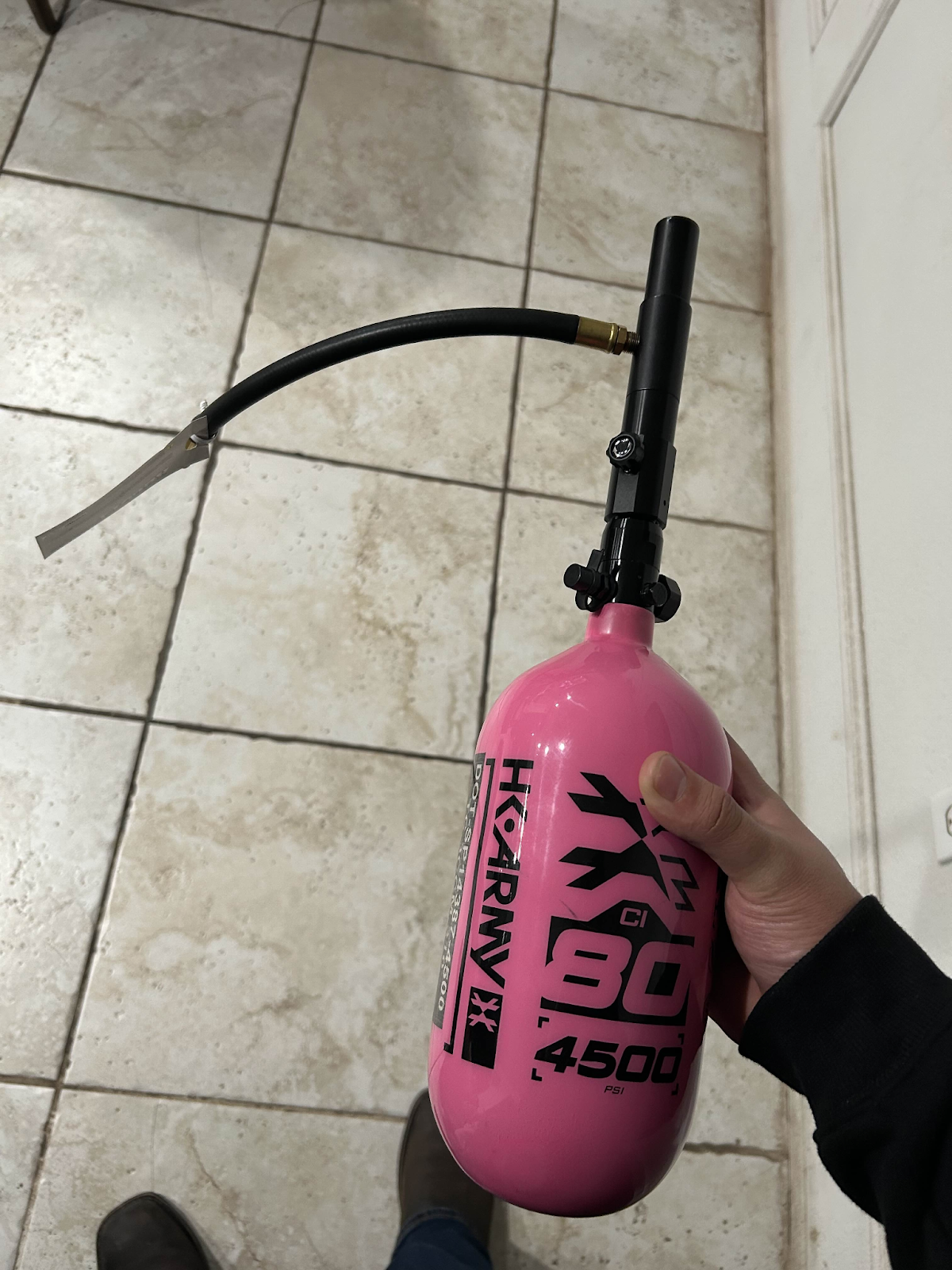
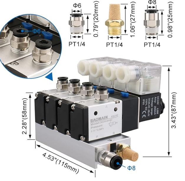
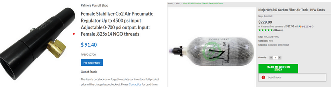


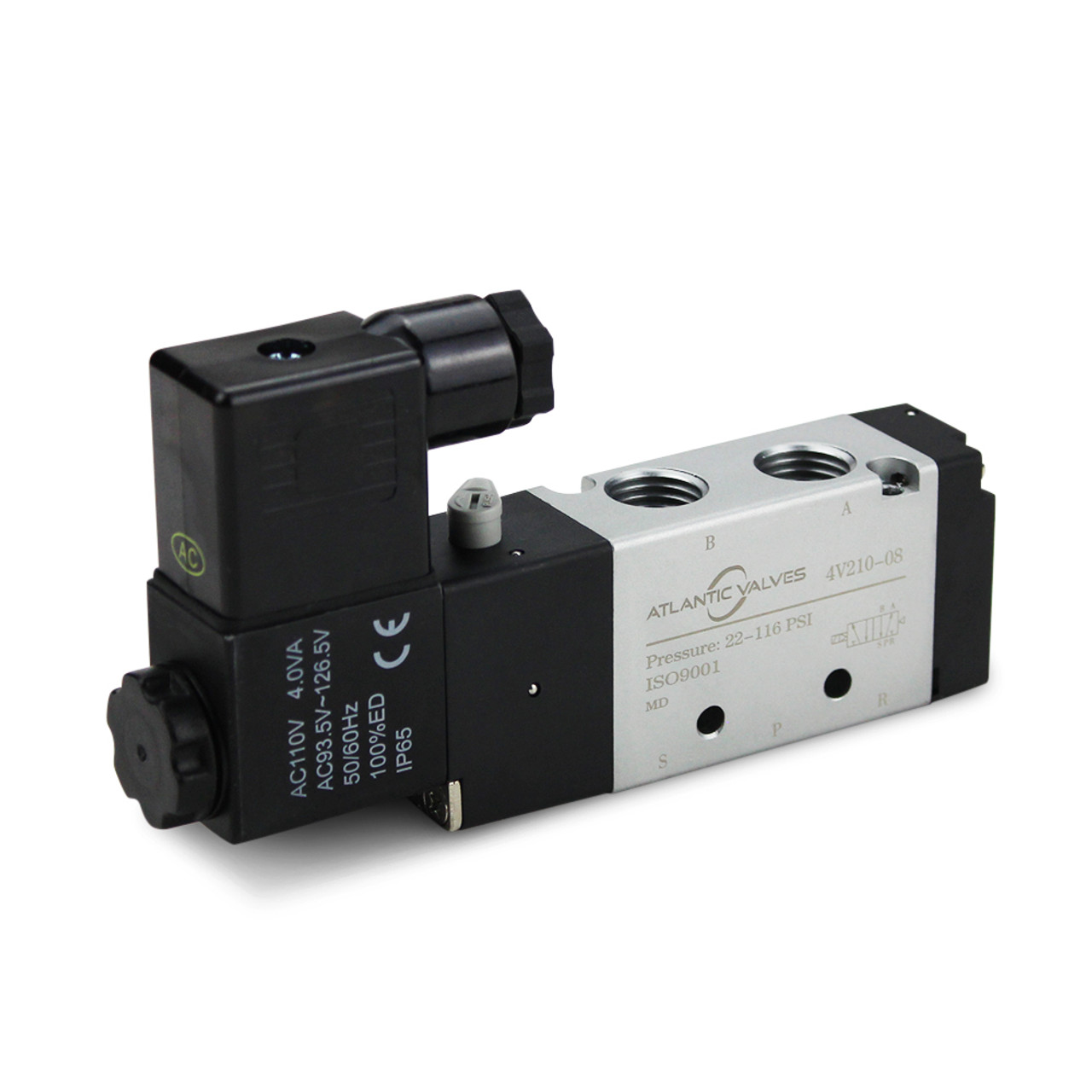


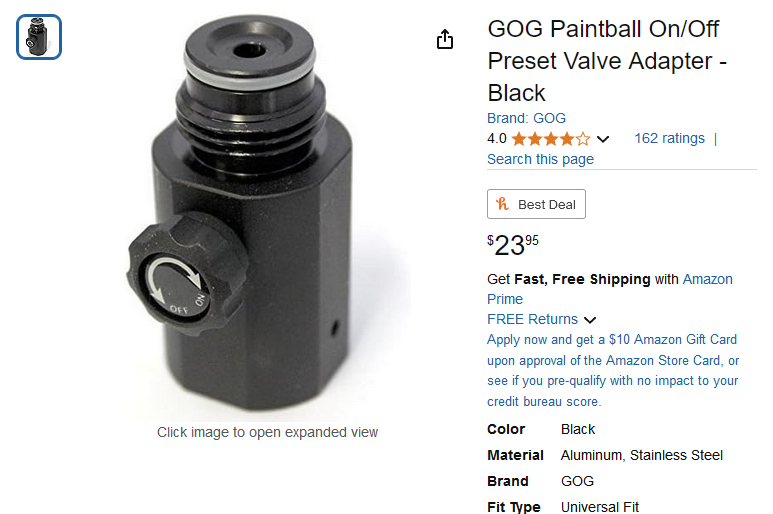

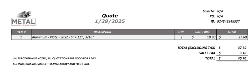
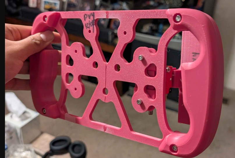
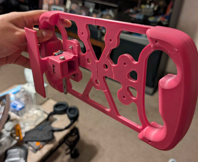
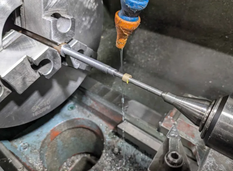
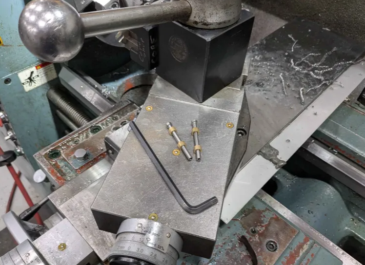

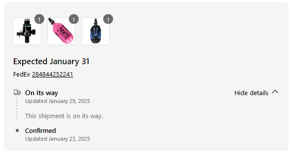
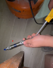

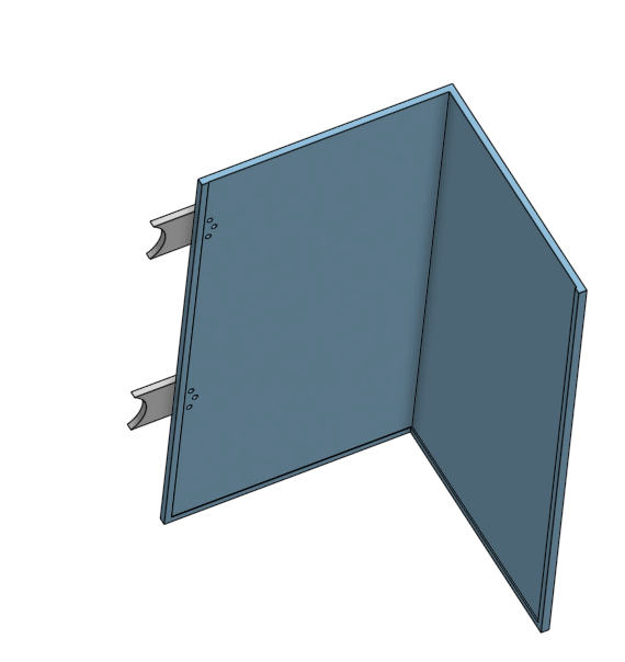

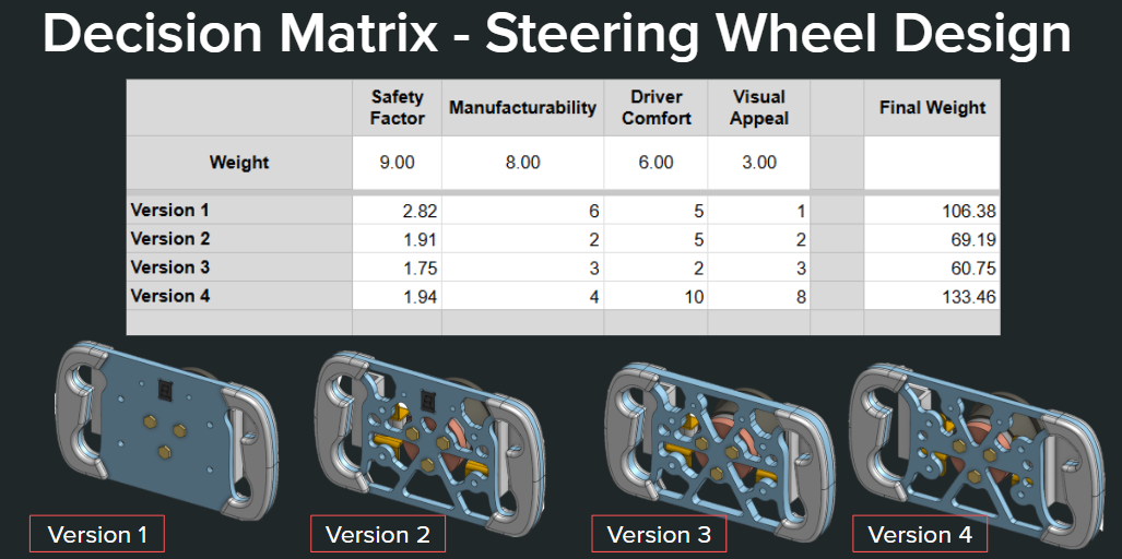 Figure 1: Decision Matrix
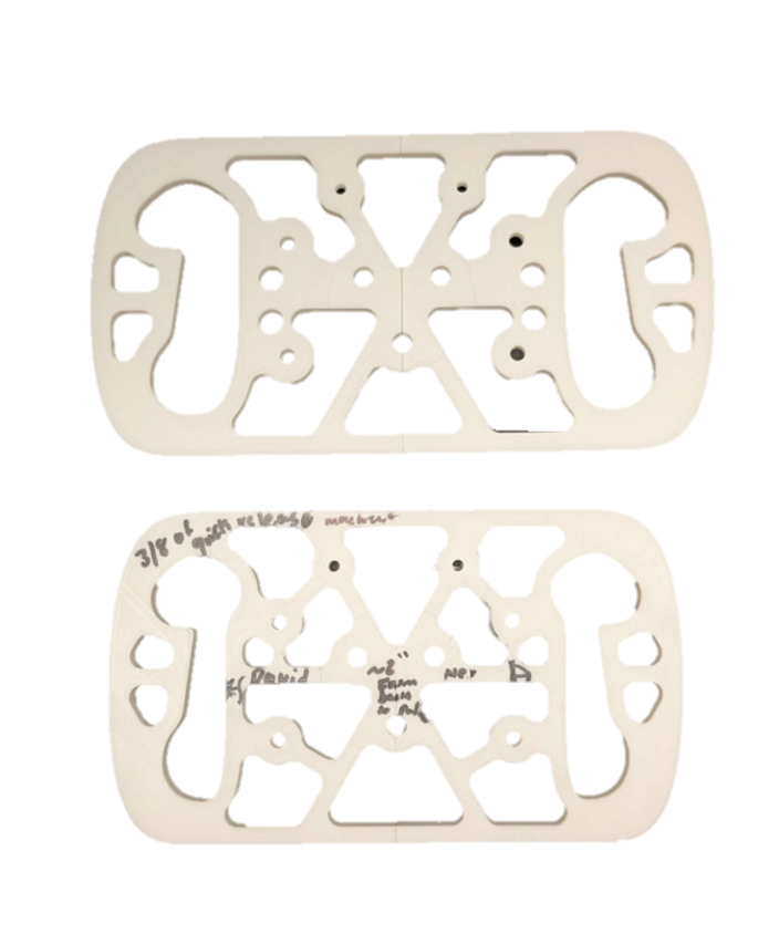 Figure 2: Steering Wheel Design Changes
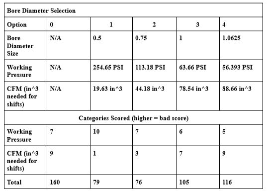 Figure 3: Tabulation for Bore Diameter Selection
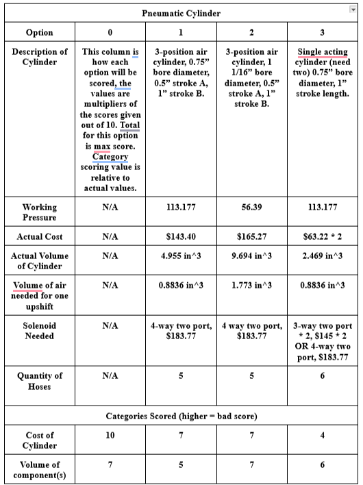
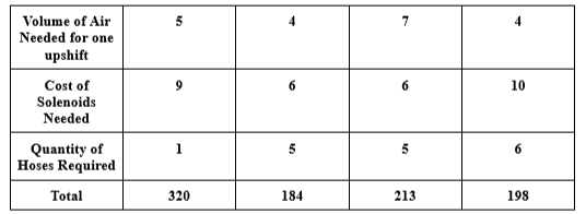 Figure 4: Tabulation for Pneumatic Cylinder Selection
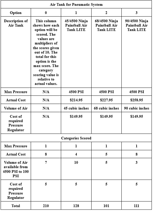 Figure 5: Tabulation for Air Tank Selection
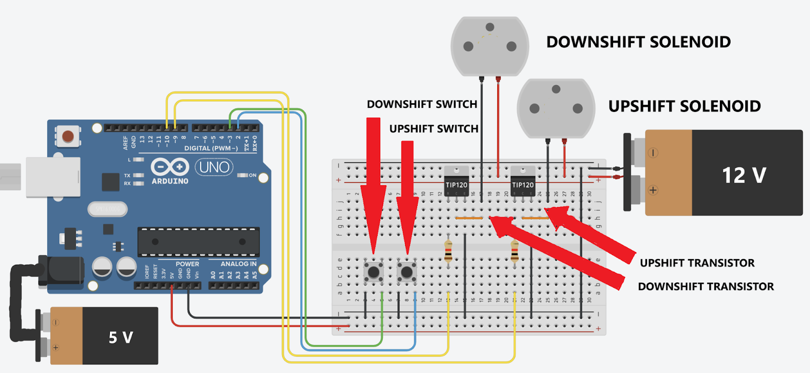
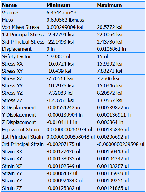 Figure 7: FEA Results
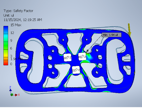

 Sample CAD of Paddle Shifters to be placed behind steering wheel