Setting up some ESPhome-devices
To make the experience fit your profile, pick a username and tell us what interests you.
We found and based on your interests.
This is controlled by automations on HA which switch on/off the valves by relays using the ESPhome switches. But what will happen if my HA crashed while the water is on? Perhaps while I'm on holiday?
to be continued
Status LED:
Most of the ESP boards have a status LED. There exists a primitive to directly access it:
light:
- platform: status_led
name: "Status"
pin:
number: GPIO2
inverted: true
restore_mode: ALWAYS_OFFThis allows easily using the status LED as an indicator when programming automations in ESPhome.
HA Button:
A switch from ESPhome shows as a switch in HA and can be toggled there. However, sometimes you would like to have the equivalent of a tactile button in HA, for example to press a button in the HA companion app on a smartphone to open a garage door.
output:
- platform: gpio
pin: GPIO0
id: gpio_d3
switch:
- platform: output
name: "Generic yellow switch"
id: yellow_switch
output: gpio_d3
button:
- platform: template
name: "Garagentor"
id: tortaster
on_press:
then:
- switch.turn_on: yellow_switch
- delay: 1s
- switch.turn_off: yellow_switch
So pressing on this button in HA turns the yellow switch on for 1 second. Similar to pressing a button for 1 second.
There exist numerous possibilities to measure temperature. On is the Dallas DS1820 sensor. It uses a single GPIO. It is necessary to define that this GPIO is used for a 1-wire bus. And then, the 1-wire bus is referenced by its id in the sensor itself:
one_wire:
- platform: gpio
pin: GPIO12
id: wire1
sensor:
- platform: dallas_temp
name: Temperatur
update_interval: 5s
one_wire_id: wire1and it shows in HA:
Considering https://community.home-assistant.io/t/homeassistant-number-how-does-it-work/842982/10 let's make the device independent from HA, i.e. add the possibility to dim the LED. The most intuitive way is perhaps a rotary button.
This can be done easily and just requires two GPIOs:
The code needs to be added to the sensor section.
sensor:
- platform: rotary_encoder
name: "Rotary Button"
pin_a: GPIO4 #D2
pin_b: GPIO5 #D1
min_value: 0
max_value: 100
on_clockwise:
- light.dim_relative:
id: red_led
relative_brightness: 5%
transition_length: 500ms
on_anticlockwise:
- light.dim_relative:
id: red_led
relative_brightness: -5%
transition_length: 500ms
The code is pretty self-explanatory.
This also turns up in the sensors field in HA. But to dim it from HA, the red LED needs to be clicked.
Of course, there need also to be inputs. For example a switch or a button. I added a button to toggle the red LED. To interact between different components, the components need to have an id. So, an id needs to be added to the red LED:
light:
- platform: monochromatic
name: "red LED"
id: red_led
output: gpio_d7
default_transition_length: 1.5sAs can be seen, the transition length can be fractions of seconds.
To add the button or switch as an input, a binary_sensor needs to be added:
binary_sensor:
- platform: gpio
name: "Button"
pin:
number: GPIO14 #D5
inverted: true
mode:
input: true
pullup: true
filters:
- delayed_on: 50ms # debouncing
on_click:
max_length: 1000ms
then:
- light.toggle: red_ledThe button connects the gpio pin to ground. Therefore, a pull-up resistor to Vcc is needed. This can be done using an internal pull-up. As the gpio goes to 0 when the button is pressed, inverted: true is used which provides a logic 1 when the button is pressed. max_length is used to define what is considered a click.
Now, the red LED can be toggled using the button and in addition its intensity can be changed from HA.
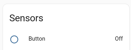
In HA, there is now an additional Sensors field which shows the state of the button:
Something you quite often want to have with lights is that you can dim them.
Ok. But don't look for something like Light-PWM. What you want to change is not the abstract light component but the underlying output. And here we find several components:
- ESP32 LEDC
- ESP8266 Software PWM
- LibreTiny PWM
- Slow PWM
As I'm working with the Wemos D1 mini which is an ESP8266 board, I choose ESP8266 Software PWM.
The first thing I have to change is a single line in my code to make the red LED dimmable:
- platform: esp8266_pwm
instead of gpio.
But a dimmable light is not a binary one any more. Therefore, this needs to be changed, too and becomes:
- platform: monochromatic
instead of binary.
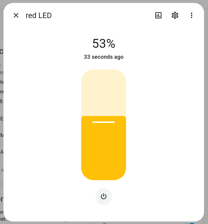
The appearance in HA is the same but when clicking on the red LED, a widget pops up where the brightness can be set to anything between 0 and 100%.
And looking at the log, the following can be seen:
[09:06:28][D][light:036]: 'red LED' Setting:
[09:06:28][D][light:047]: State: ON
[09:06:28][D][light:051]: Brightness: 53%
[09:06:28][D][light:085]: Transition length: 1.0s
[09:06:31][D][light:036]: 'red LED' Setting:
[09:06:31][D][light:047]: State: OFF
[09:06:31][D][light:085]: Transition length: 1.0s
[09:06:32][D][light:036]: 'red LED' Setting:
[09:06:32][D][light:047]: State: ON
[09:06:32][D][light:085]: Transition length: 1.0s
There is something called "Transition length" which defines how long it takes to fade-in/fade-out. And with the button below the slider, the light can be switched on/off. But "on" is then the previously set intensity. In the above case it means it will return again to 53% intensity - not to 100%.
Looking into the documentation, (https://esphome.io/components/light/#config-light) there are plenty of possibilities for setting parameters like default_transition_length but not all can be used with the monochromatic light.
For example:
light:
- platform: monochromatic
name: "red LED"
output: gpio_d7
default_transition_length: 3s
This can be something like a LED or a relay that can be switched by switching a digital output.
There are several possibilities to do this which end up in slightly different appearances in HA:
Output - GPIO
output:
- platform: gpio
pin: GPIO13
id: gpio_d7
But this does not show up in HA.
If you want it to be shown in HA, you can for example use
Light - Binary Light
You need to add a few lines to the above. The result is:
output:
- platform: gpio
pin: GPIO13
id: gpio_d7
light:
- platform: binary
name: "red LED"
output: gpio_d7
As you see, in the light you refer to the output's id.
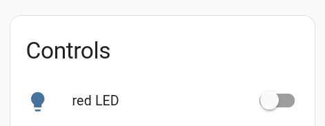
The result looks like this in HA:
You could also define a
Switch - GPIO Switch
The code is:
switch:
- platform: gpio
name: "Yellow output"
pin: GPIO12
Result:
or you can use
Switch - Generic Output Switch
Replace the above code with:
output:
- platform: gpio
pin: GPIO12
id: gpio_d6
switch:
- platform: output
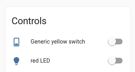
name: "Generic yellow switch"
output: gpio_d6
Beware, you can have only a single output section. So together with the red LED it looks like:
output:
- platform: gpio
pin: GPIO12
id: gpio_d6
- platform: gpio
pin: GPIO13
id: gpio_d7
light:
- platform: binary
name: "red LED"
output: gpio_d7
switch:
- platform: output
name: "Generic yellow switch"
output: gpio_d6
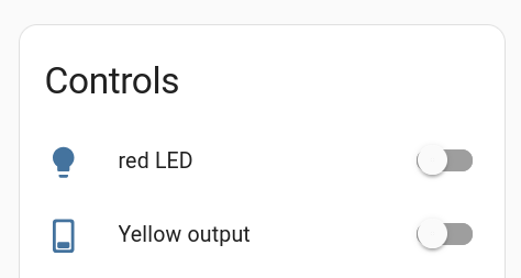
And the result in HA:
And there are other components which in the end only toggle a GPIO between 0 and 1.
The more I used ESPhome, the more confused I got. So I decided to start over again and provide some examples for things I had understood or which at least I thought I had understood.
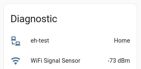
I took a Wemos D1 mini board and generated a new yaml to which I just added a wifi sensor, as it's always good to know the wifi strength when testing.
esphome:
name: eh-test
esp8266:
board: d1_mini
# Enable logging
logger:
# Enable Home Assistant API
api:
password: ""
ota:
- platform: esphome
password: ""
wifi:
ssid: !secret wifi_ssid
password: !secret wifi_password
# Enable fallback hotspot (captive portal) in case wifi connection fails
ap:
ssid: "Eh-Test Fallback Hotspot"
password: "password"
captive_portal:
sensor:
- platform: wifi_signal
name: "WiFi Signal Sensor"
update_interval: 10s
As for the wifi credentials, it's necessary to create a secrets.yaml in the same directory as the above yaml file and provide the credentials there:
wifi_ssid: "your_ssid"
wifi_password: "your_secret_password"
In home assistant (HA) this can then be seen as
(Settings -> Devices & Services -> ESPHome -> Devices)
After my first positive experiences with ESPhome, I had a closer look into the documentation and found out that deepsleep is also implemented.
I had some soil moisture sensors connected to an ESP8266 to detect if irrigation is necessary. The device is powered by an 18650 cell. It wakes up every 30 mins, switches on the power to the sensor, reads the sensor, sends the measured value via MQTT and goes back to deep sleep. It was not too difficult to implement it in ESPhome:
esphome:
name: eh-bodenfeuchte3
on_boot:
- switch.turn_on: Sensor_Vcc
- delay: 1s
# Terrassensensor
esp8266:
board: huzzah
# Enable logging
logger:
# Enable Home Assistant API
api:
password: ""
ota:
- platform: esphome
password: ""
wifi:
ssid: !secret wifi_ssid
password: !secret wifi_password
# Enable fallback hotspot (captive portal) in case wifi connection fails
ap:
ssid: "Eh-Bodenfeuchte3"
password: "EfGXNoIANTV5"
captive_portal:
deep_sleep:
run_duration: 12s
sleep_duration: 30min
id: ds
switch:
- platform: gpio
pin: GPIO14 #D5
id: Sensor_Vcc
binary_sensor:
- platform: homeassistant
id: no_deep_sleep
entity_id: input_boolean.no_deep_sleep
mqtt:
broker: 192.168.2.204
discovery: false
discover_ip: false
sensor:
- platform: wifi_signal
name: "WiFi Signal Sensor"
update_interval: 10s
- platform: adc
pin: A0
name: Terrassenfeuchte
samples: 10
update_interval: 8s
id: terrassenfeuchte
filters:
- multiply: 1000
on_value:
- mqtt.publish:
topic: "ESP/H2O/Sensor3"
payload: !lambda |-
return to_string(int(1*id(terrassenfeuchte).state));
retain: true
- if:
condition:
binary_sensor.is_on: no_deep_sleep
then:
- deep_sleep.prevent: ds
# - logger.log: "No sleep!"
else:
- deep_sleep.allow: ds
# - logger.log: "Let's snooze!"
Each time it wakes up, the **on_boot**-section is carried out. There I switch on the voltage for the sensor. As it does not draw much current, I power it directly from a GPIO.
The implementation in ESPhome allowed me even to add a switch to HA to prevent the device from going to deep sleep again after the next time it wakes up again. This allows easily flashing OTA without opening the waterproof housing. A feature which I did not have before.
I put the device into the soil in April and remove it at the end of October. I charge the cell at the beginning of August to be sure that it lasts. That's good enough for me.
An incomplete yaml file to control two LED strips for illumination using two buttons. The buttons allow only to switch between on and off. From HomeAssistant dimming is possible.
The device uses a Wemos D1 mini.
The LEDs are controlled using PWM output and are connected using a logic-level n-MOSFET (IRLU 024N). The maximum level is set to 95% to prevent the LEDs from to early degradation (at least I hope so).
The buttons used to toggle the lights include a very simple debouncing (filter).
esp8266:
board: d1_mini
# LEDs: 13, 14 (D7, D5)
# Taster: 5, 4 (D2, D1)
output:
- platform: esp8266_pwm
pin: GPIO14 #D5
id: Fenster_pwm
frequency: 440 Hz
min_power: 0
max_power: 0.95
- platform: esp8266_pwm
min_power: 0
max_power: 0.95
frequency: 440 Hz
id: Bett_pwm
pin: GPIO13 #D7
light:
- platform: monochromatic
name: "Licht Fenster"
id: Licht_Fenster
output: Fenster_pwm
default_transition_length: 3s
- platform: monochromatic
name: "Licht Bett"
id: Licht_Bett
output: Bett_pwm
default_transition_length: 3s
# - platform: status_led
# name: "Status"
# pin:
# number: GPIO2
# inverted: true
# restore_mode: ALWAYS_OFF
binary_sensor:
- platform: gpio
name: "Taster_Fenster"
pin:
number: GPIO4 #D1
inverted: true
mode:
input: true
pullup: true
filters:
- delayed_on: 50ms
on_click:
max_length: 500ms
then:
- light.toggle: Licht_Fenster
- platform: gpio
name: "Taster_Bett"
pin:
number: GPIO5 #D2
inverted: true
mode:
input: true
pullup: true
filters:
- delayed_on: 50ms
on_click:
max_length: 500ms
then:
- light.toggle: Licht_Bett
sensor:
- platform: wifi_signal
name: "WiFi Signal Sensor"
update_interval: 300s
Create an account to leave a comment. Already have an account? Log In.
Become a member to follow this project and never miss any updates