John Anderson
-
More Detail Regarding Programming AVRs
01/04/2025 at 19:13 • 0 commentsI built the "Atari" workstation to program Microchip AVR microcontrollers that support UPDI programming. I use these microcontrollers in various projects I build for fun.
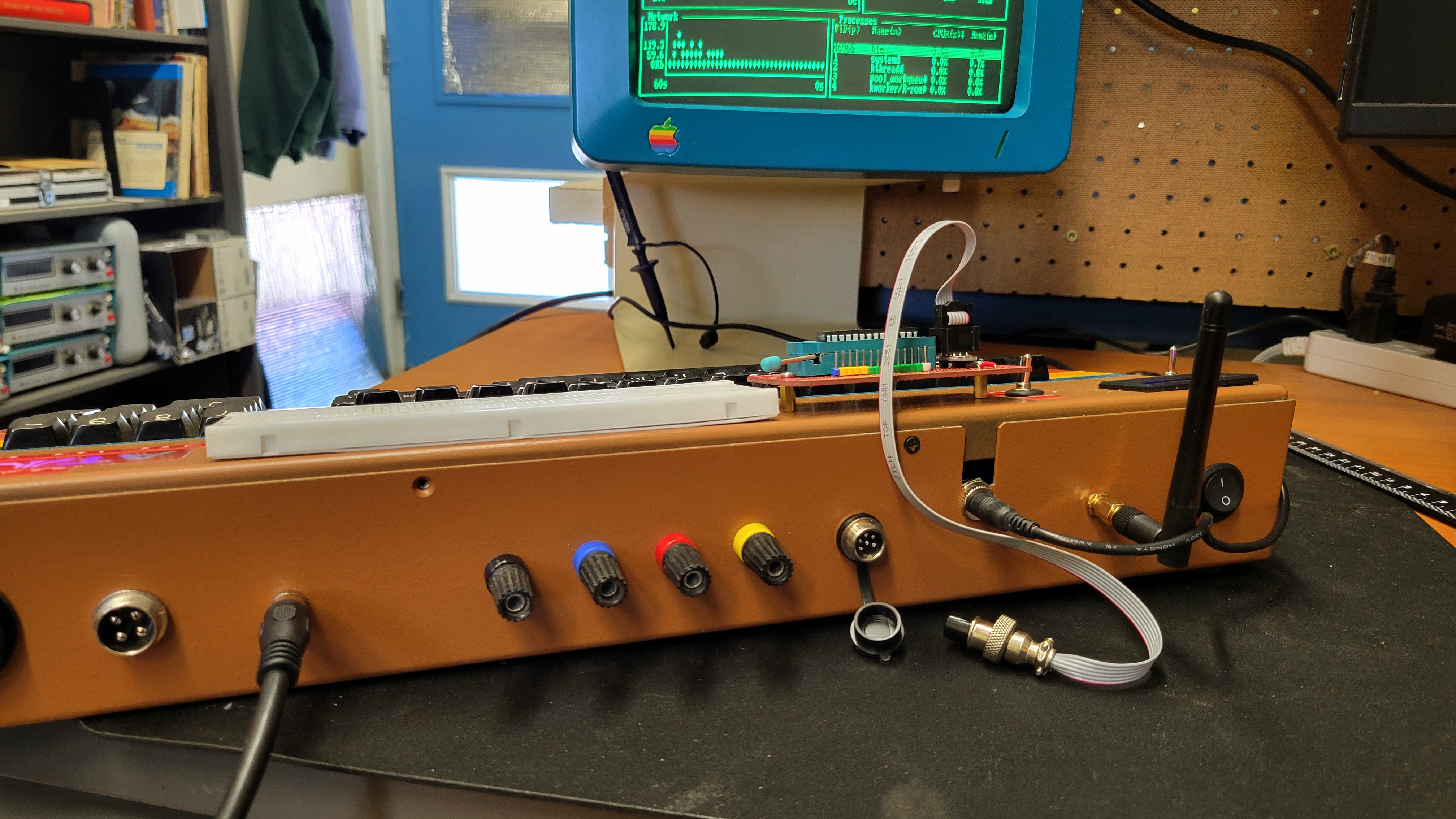
On the back of the workstation, there is a 6 pin aviation style connector. It is the programming port for the AVR UPDI interface.
![]()
Various cables with different connectors can be built. This one has a standard AVR ISP 6 pin IDC layout. So, it can work with existing AVR based board with an ISP connector.
The soldered protoboard mounted on the face of the workstation is for AVRxxxDA28 and AVRxxxDB28 DIP parts. Different protoboards can be built and mounted there for other AVR target processors.
![]()
For more detailed information about how this is connected to the Raspberry PI inside the case, checkout this link to a document describing a Raspberry PI 4 model B Development Platform for avrOS on my github page.
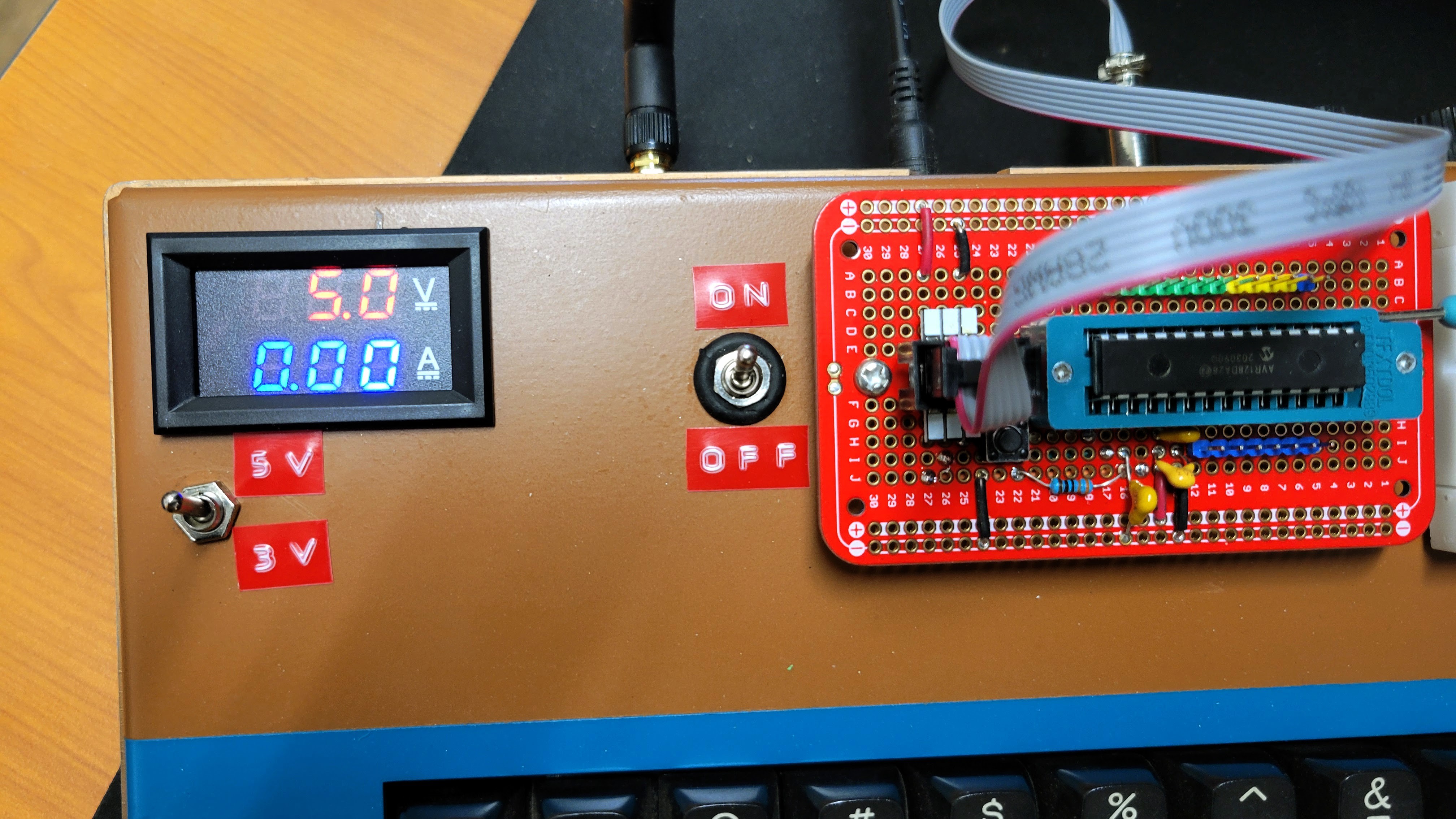
The "Atari" workstation has one addition feature for this AVR UPDI interface. The voltage of the power supplied to the programming interface is selectable between 5v and 3.3v.
![]()
This requires an additional level shifter to be added between the PI and the programming port. In addition, I added a volt/amp meter to display the voltage and current supplied on that port.
With all of this setup and connected, I can program AVR DA parts.
![]()
-
Final thoughts on PI video configuration
12/19/2024 at 16:54 • 0 commentsI present two different means to configure the PI video. The first one uses the old PI driver with the pivec app to fix a problem with it. The second one uses the new PI driver without any need for an additional app to deal with problems. Here's a summary of the pro's and con's that I am aware of.
Old Driver w/pivec
Pro
- You can tweak the screen resolution with the framebuffer_width and framebuffer_height parameters in the config.txt file. Using this and the console font selection allows you to setup exactly how many characters you want on the screen (up to 90x30)
- All the configuration is in the config.txt file
- The driver is reasonably documented
Con
- You have to build and install and use the pivec app to get rid of the annoying dithering
- The pivec app runs with root permissions and pokes at a hardware register
- This driver is no longer supported, so no new updates
New Driver
Pro
- This driver is supported
- You don't need to install pivec
- Slightly clearer at the full 720x240 resolution
Con
- You can't change the screen resolution. You are stuck with 720x240
- The console screen fonts only give you options for 8x8 and 8x14 fonts. So your options are only 90x30 or 90x17 characters. There are larger fonts for even few characters on the screen, but the precision is very granular
- Cryptic control of the driver using cmdline.txt. It is not documented anywhere. You have to search the PI forums and experiment
-
Update on video config for PI
12/19/2024 at 05:04 • 0 commentsAfter getting feedback from the developer, I figured out how to get the new vc4-kms-v3d driver to work with US NTSC monochrome displays. Using this approach you don't need the pivec application. As I mentioned before, the requirement for these displays is 240 line progressive scan (240p) and getting the chroma signal turned off.
To get it to work, first edit /boot/firmware/config.txt. Edit/add these lines:
dtoverlay=vc4-kms-v3d,composite
#sdtv_mode=16
#sdtv_aspect=1
#enable_tvout=1
#framebuffer_width=720
#franebuffer_height=224
#overscan_left=16
Note: These are the opposite of what I provided in the previous post. The # character "comments out" that line. It's also an option to just delete the lines starting with the # above.
Then edit /boot/firmware/cmdline.txt. This file is just one line. Add the following to the end of that line.
video=Composite-1:720x240M@60,tv_mode=Mono,margin_left=40,margin_right=26,margin_top=16,margin_bottom=16
Note: You will likely have to tweak the margin settings to work with your TV/monitor.
If you have already installed pivec and made it boot from the makefile. Go to the pivec directory and run the following command to remove it from the boot sequence.
make unboot
Then you just reboot and you should see your settings.
Tip: Using the raspi-config application enable SSH. You'll find that option in the Interface Options.
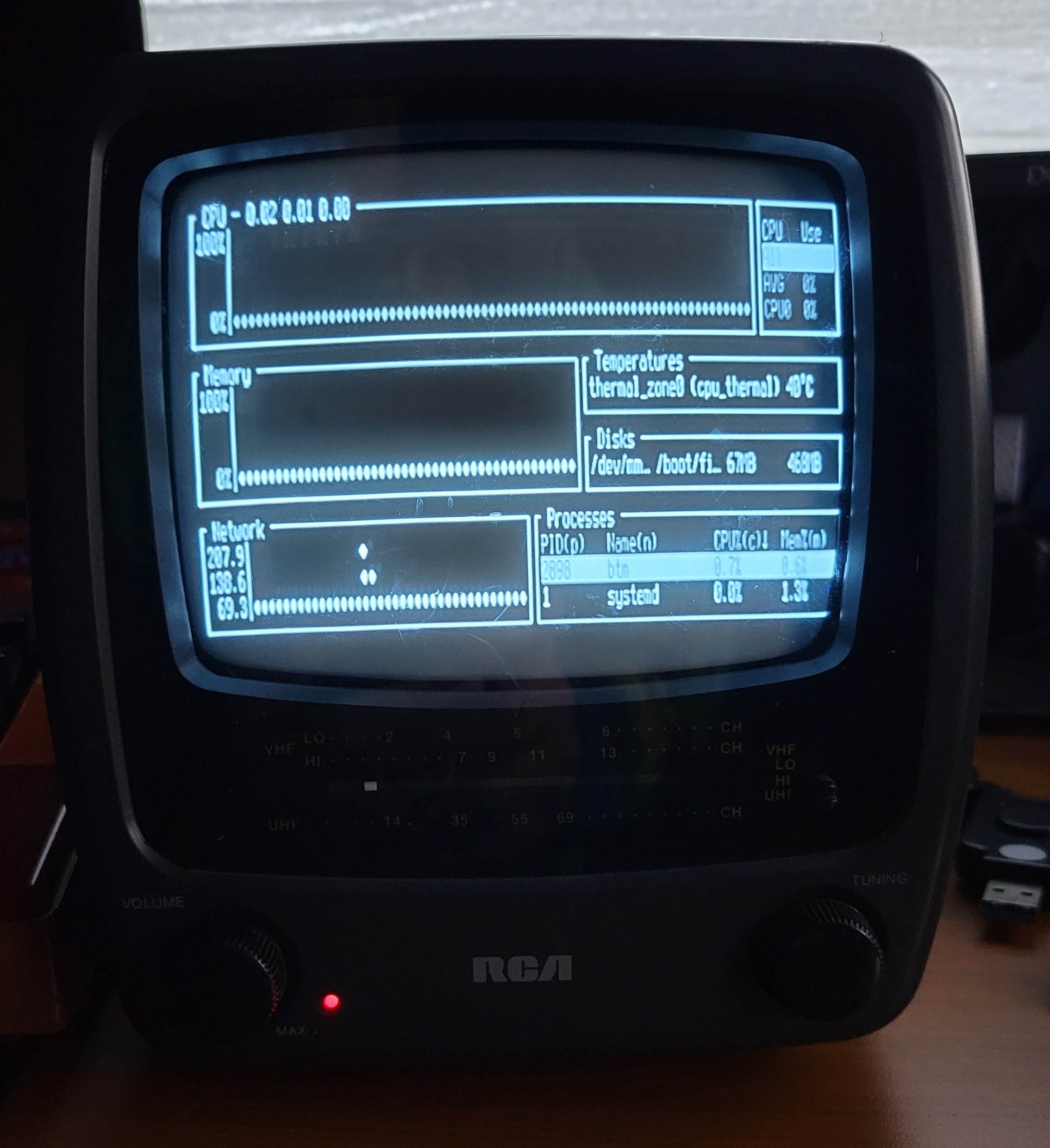
Here's an example of these settings on PI 4B connected to a cheap old US market RCA 5" B&W TV. This is the Terminus 8x14 font to make it a little more legible.
![]()
Note: The image is sharper and higher contrast in person. My camera phone doesn't do it justice.
-
Setup your PI to drive a retro B&W TV or Monochrome Monitor
12/18/2024 at 05:14 • 0 commentsIn the previous post where I mentioned pivec, I glossed over the other details of setting up your PI to output 240p composite video. If you are using an old B&W TV or monochrome monitor in the US, you'll want to use 240p because the altenative 480i mode will cause very annoying flicker. It gives me a headache in just a few minutes.
The video related lines in my config.txt looks like this:
#dtoverlay=vc4-kms-v3d
sdtv_mode=16
sdtv_aspect=1
enable_tvout=1
framebuffer_width=720
franebuffer_height=224
overscan_left=16
enable_tvout=1 enables the composite video out. sdtv_mode=16 sets it to 240p. You can play with the framebuffer and overscan settings to get the picture right for your display.
Note: this setup uses the legacy PI video driver. The new driver has 240p mode, but I haven't been able to set it up with the chroma signal disabled. If I use pivec to disable it, it will reset those bits on the next screen blank. So, I won't use that driver until it supports a Mono mode with the 240p configuration.
To install pivec, run the following commands from the command line.
git clone https://github.com/racerxr650r/pivec
cd pivec
make prereqs
make boot
-
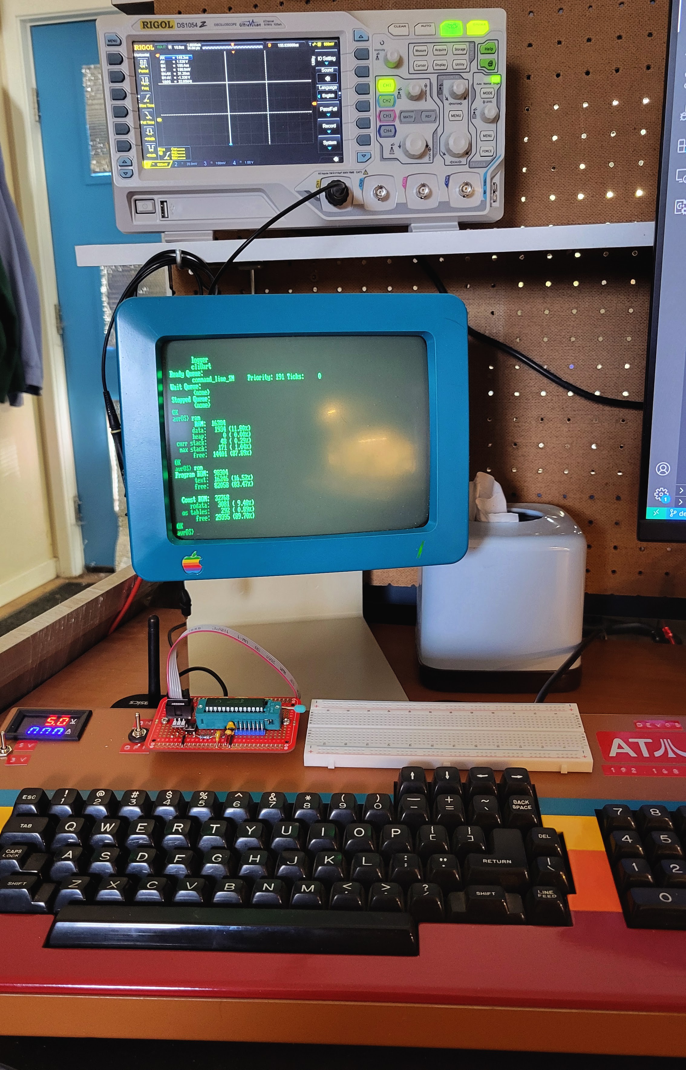
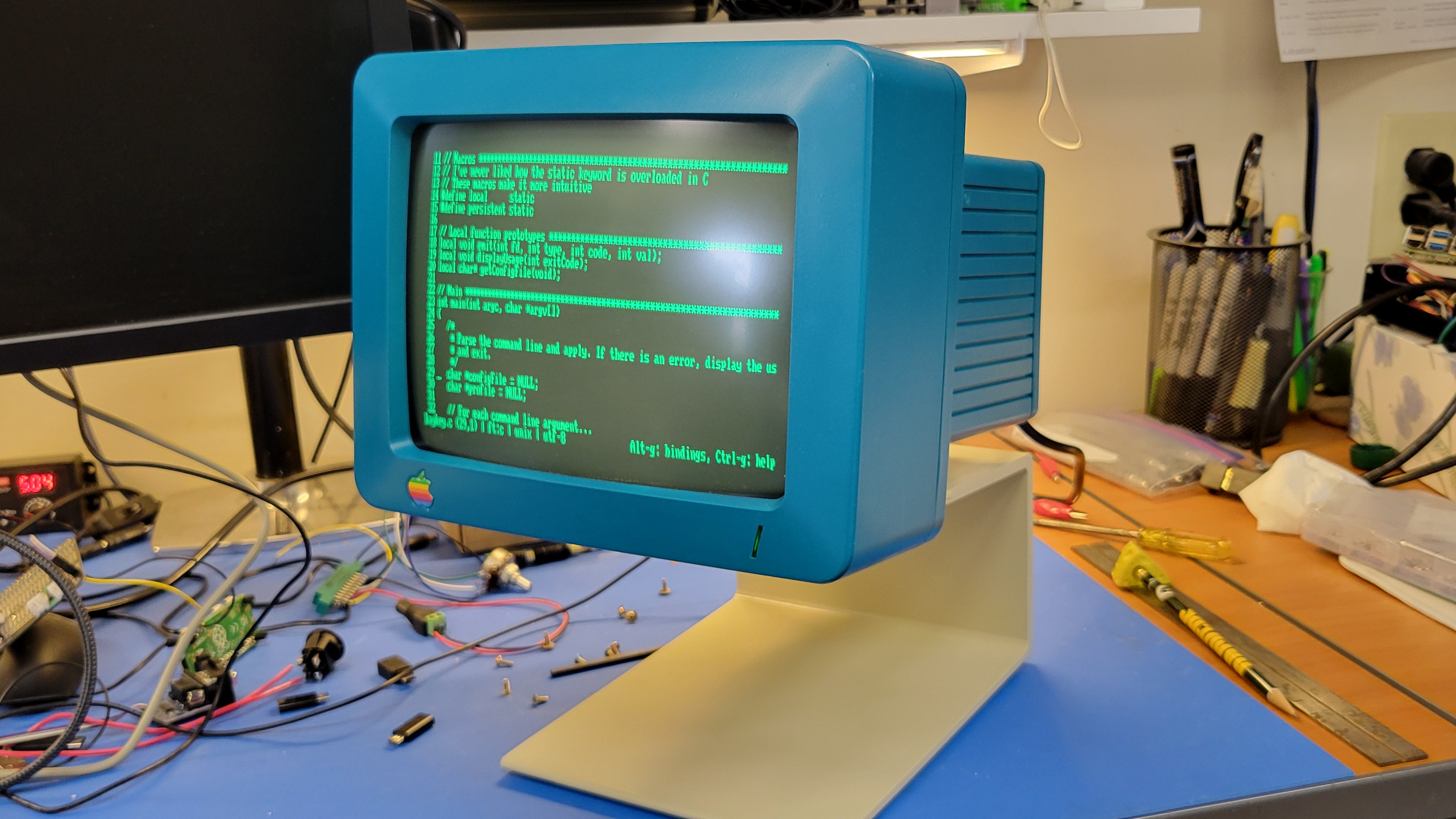
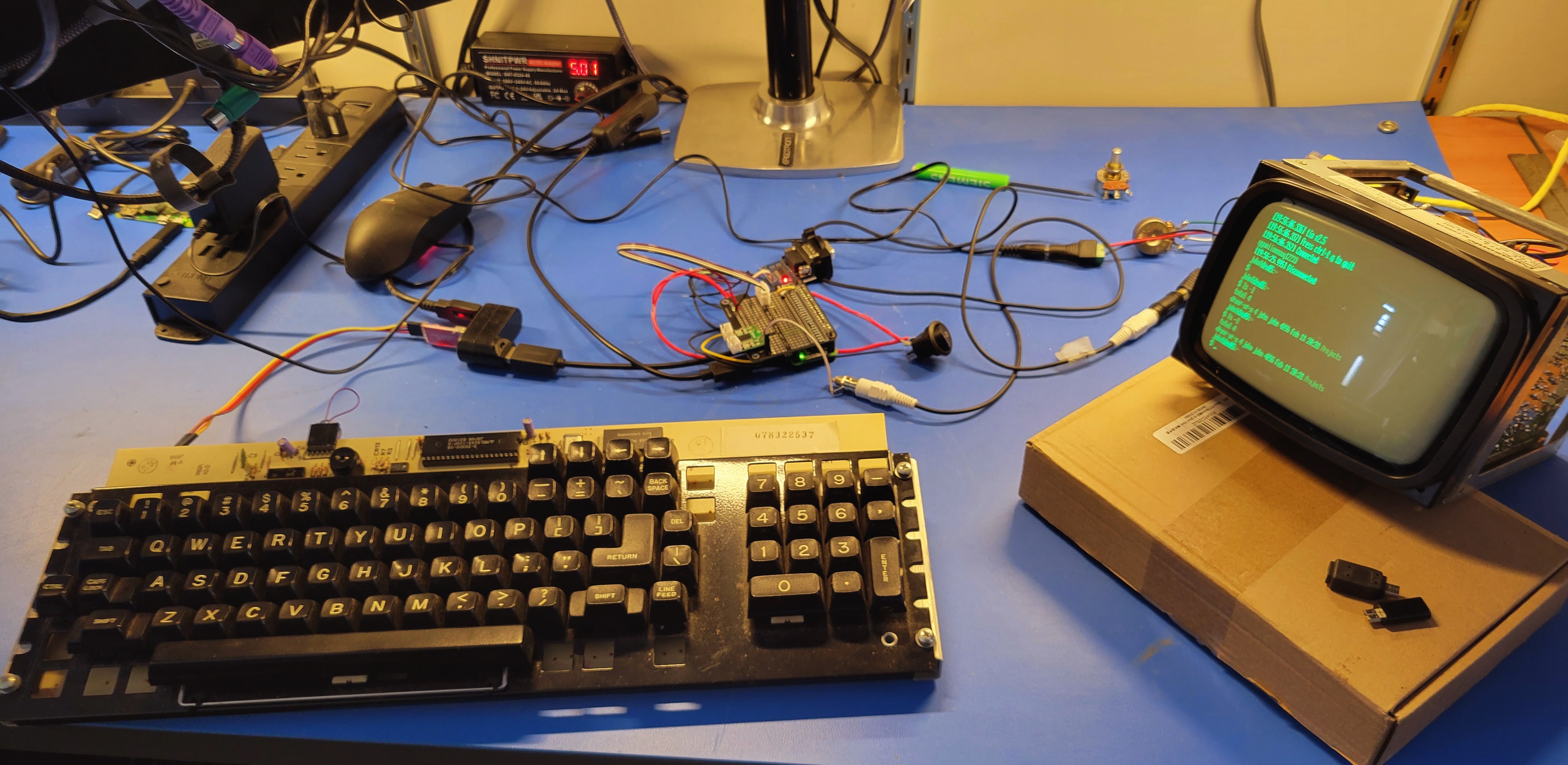
Programming AVRs
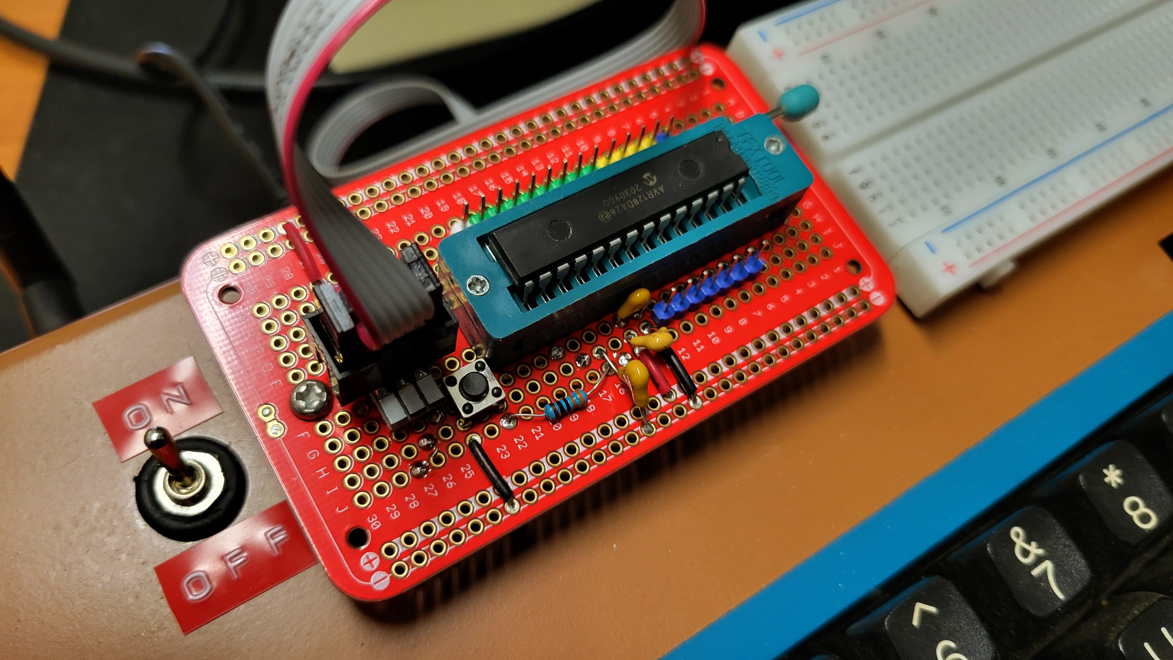
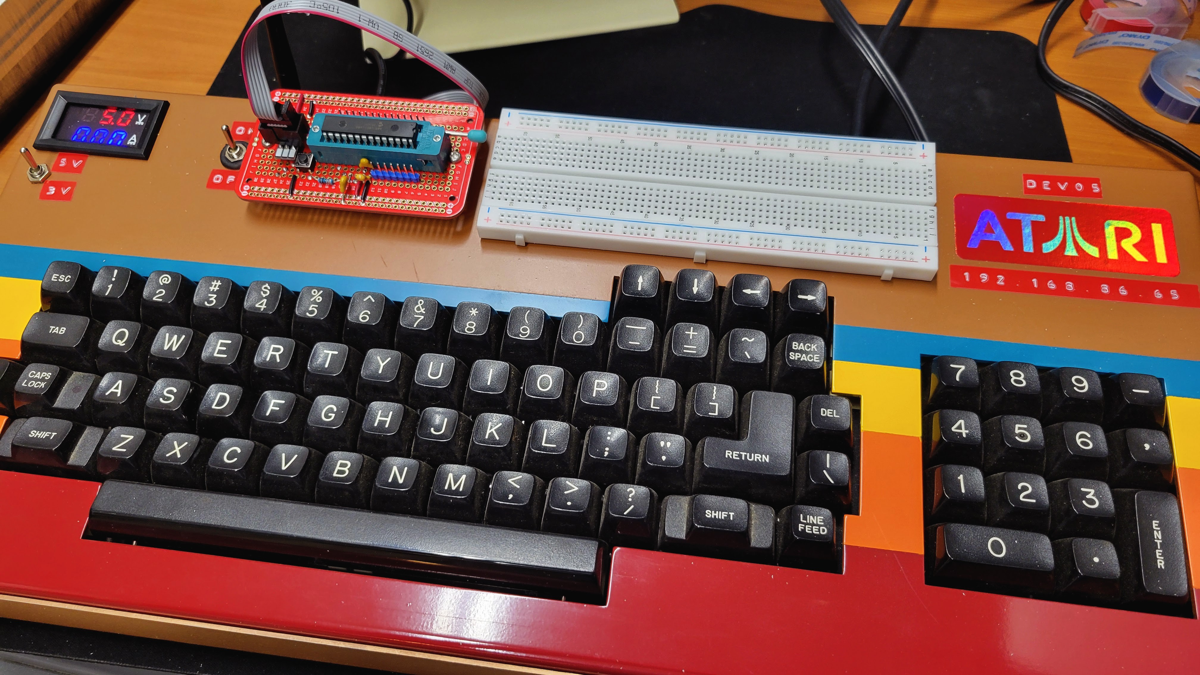
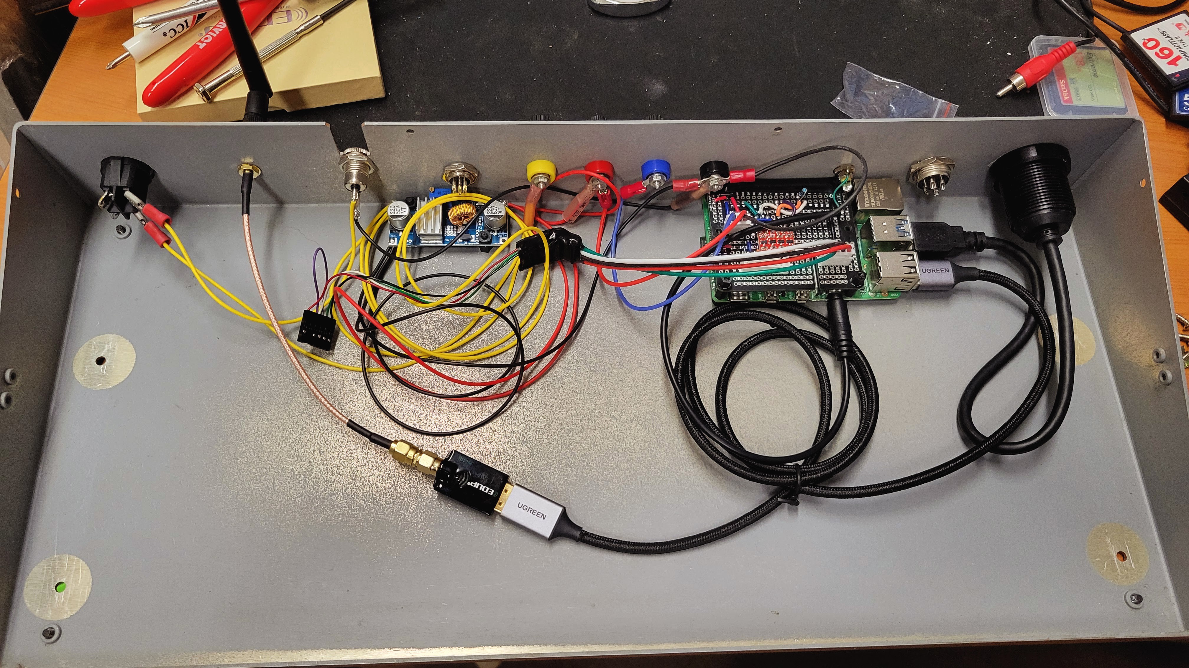
12/15/2024 at 18:44 • 0 commentsAs mentioned before, the PI has custom hat with a level shifter for a couple serial tx/rx lines from the PI. These and the power going to the 6 pin programming port are selectable between 3.3v and 5v via a toggle switch on the faceplate. The Volt/Amp meter next to the voltage selection switch displays the voltage and current draw of the Vcc pin on the programming port. Lastly, there is an on/off toggle switch that disable the programming port to make it safe to plug and unplug the cable.
![]()
The programming protoboard is replaceable for different AVR parts. The one shown is for the most common AVR part I use in projects, the AVR128DA28. The programming cable to the board can be used for programming the AVR and for debug. The cable may also be disconnected from the protoboard and plugged into one of my project boards for in circuit programming or debug.
You can see here how the cable connects using an aviation style connector at the back of the workstation and the standard AVR 6 pin ISP on the other end of the cable.
![]()
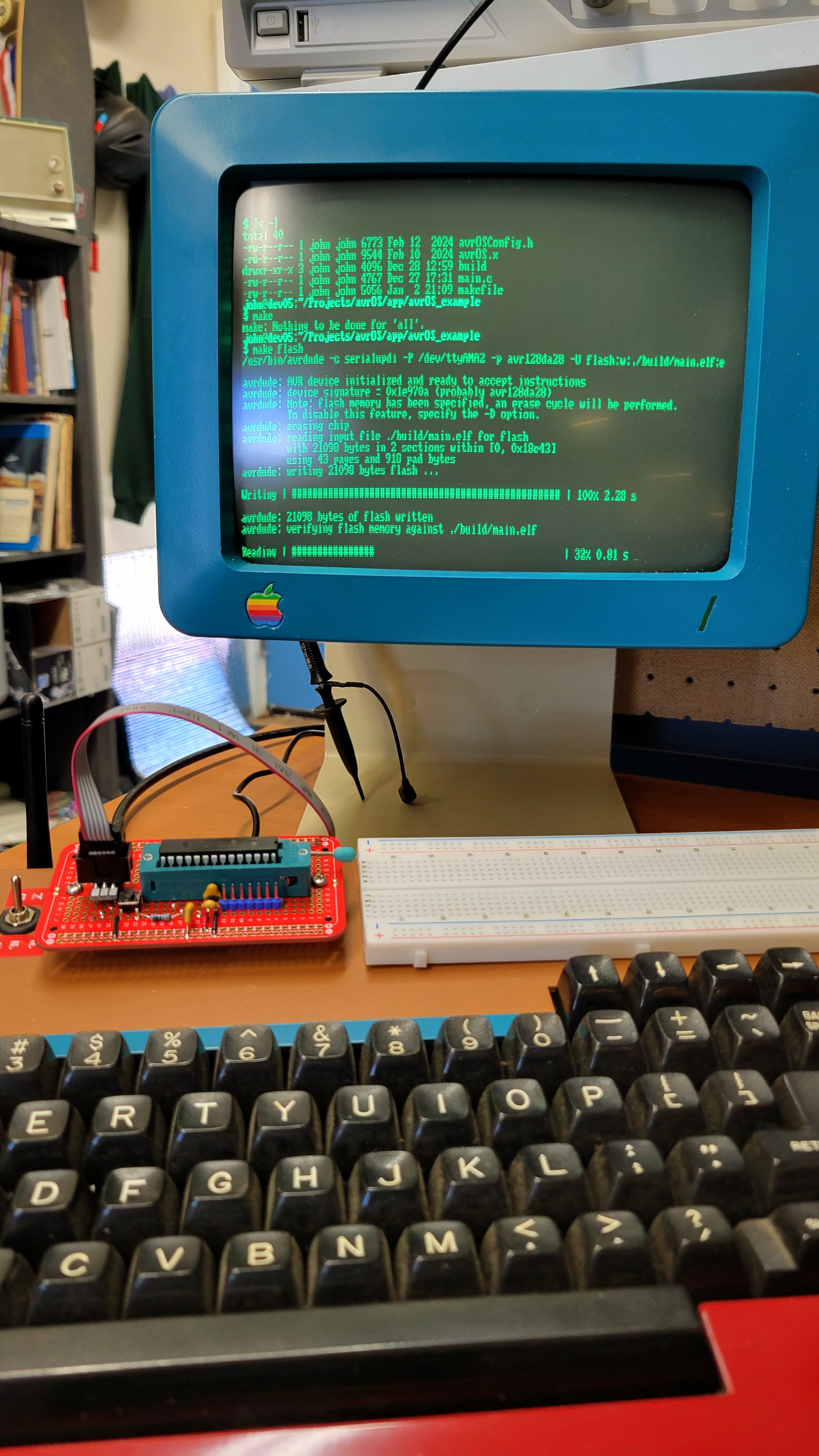
The serial TX/RX lines from the PI implement the UPDI programming interface to the AVR and another TX/RX pair for CLI interface to the application programmed on the AVR. This CLI can be used for development, debugging, and testing. I'm developing a tiny embedded OS for the AVR called avrOS that implements a state machine scheduler, events, queues, CLI, logger, and some basic AVR device drivers.
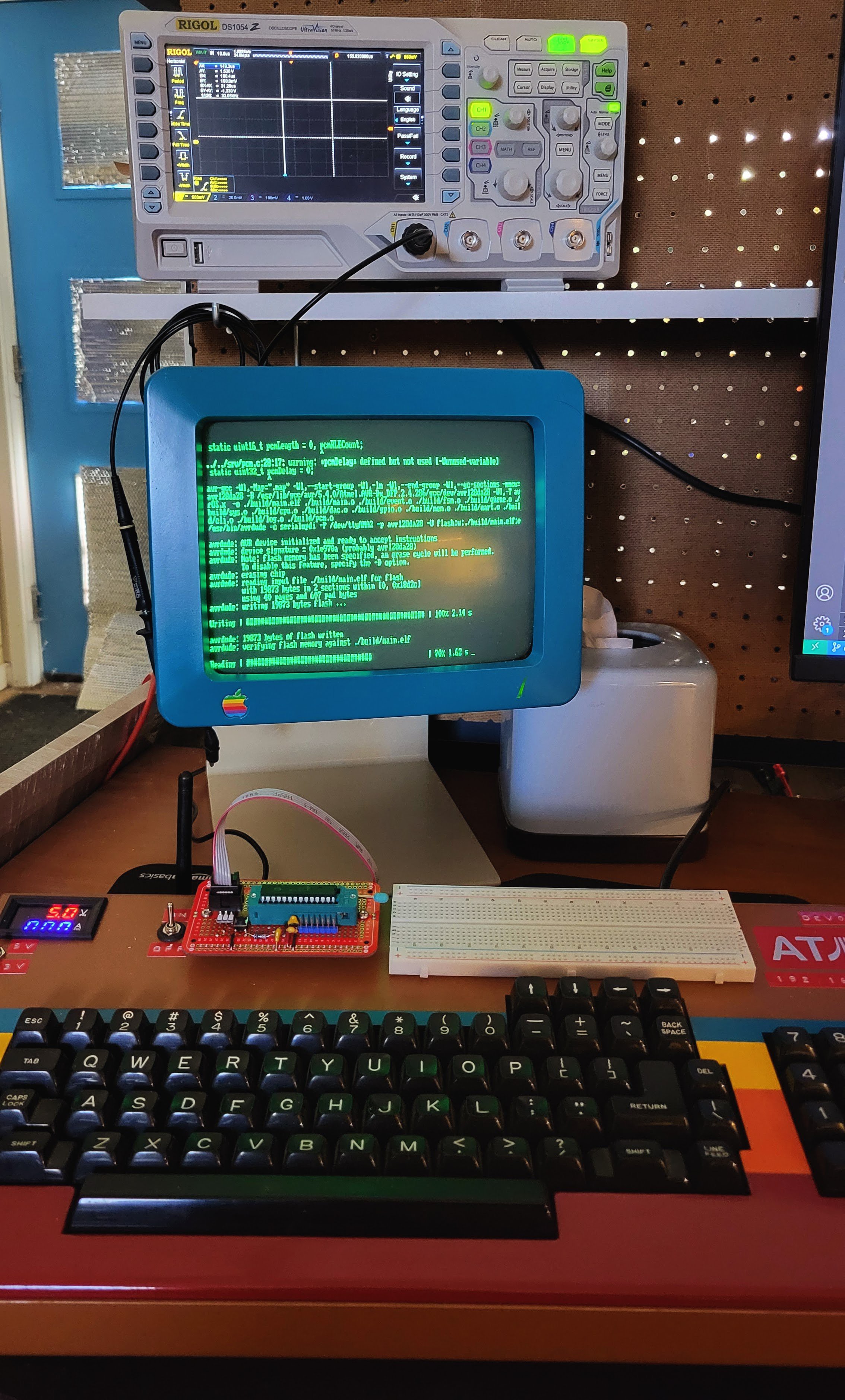
You can see programming an AVR part here.
![]()
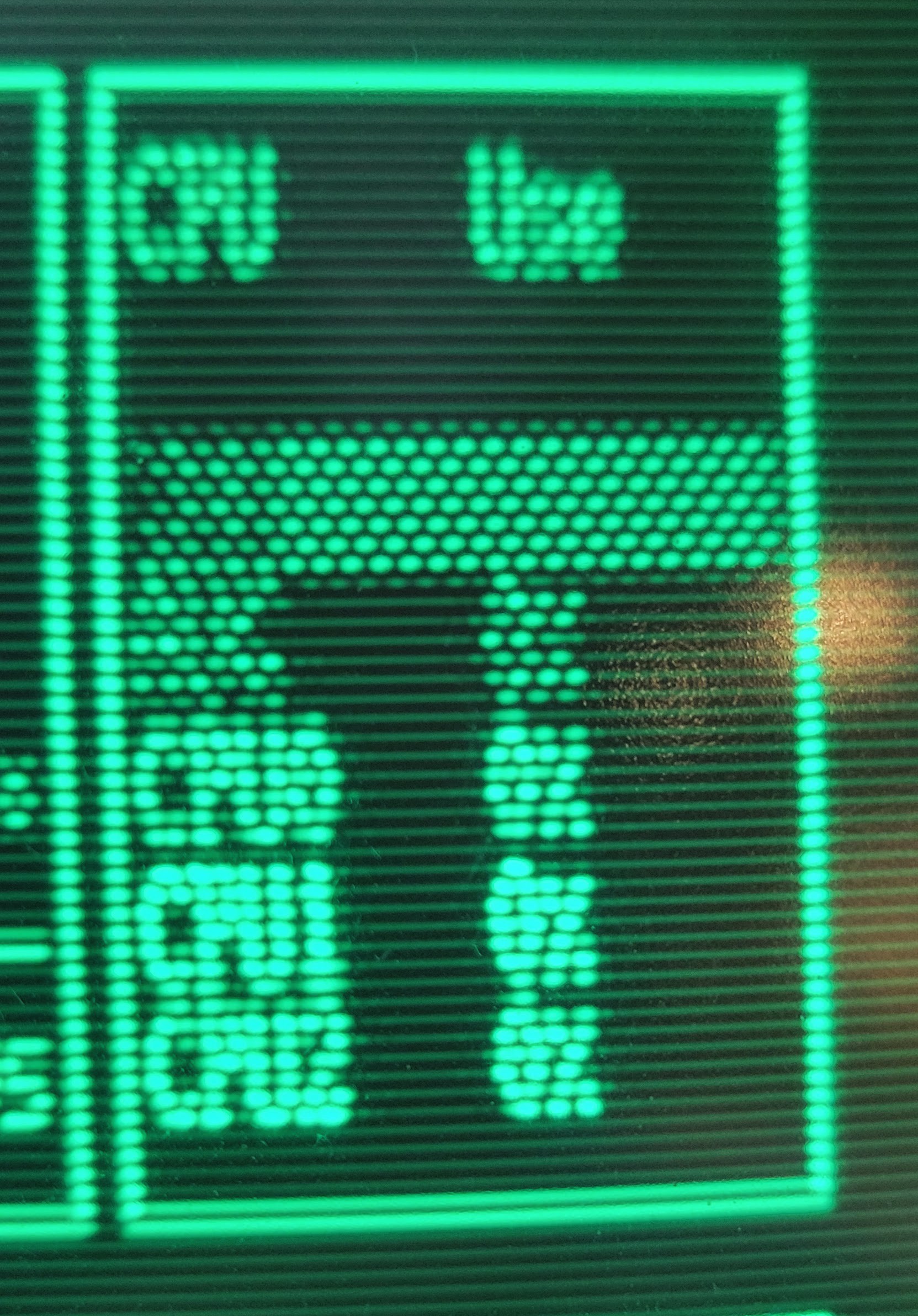
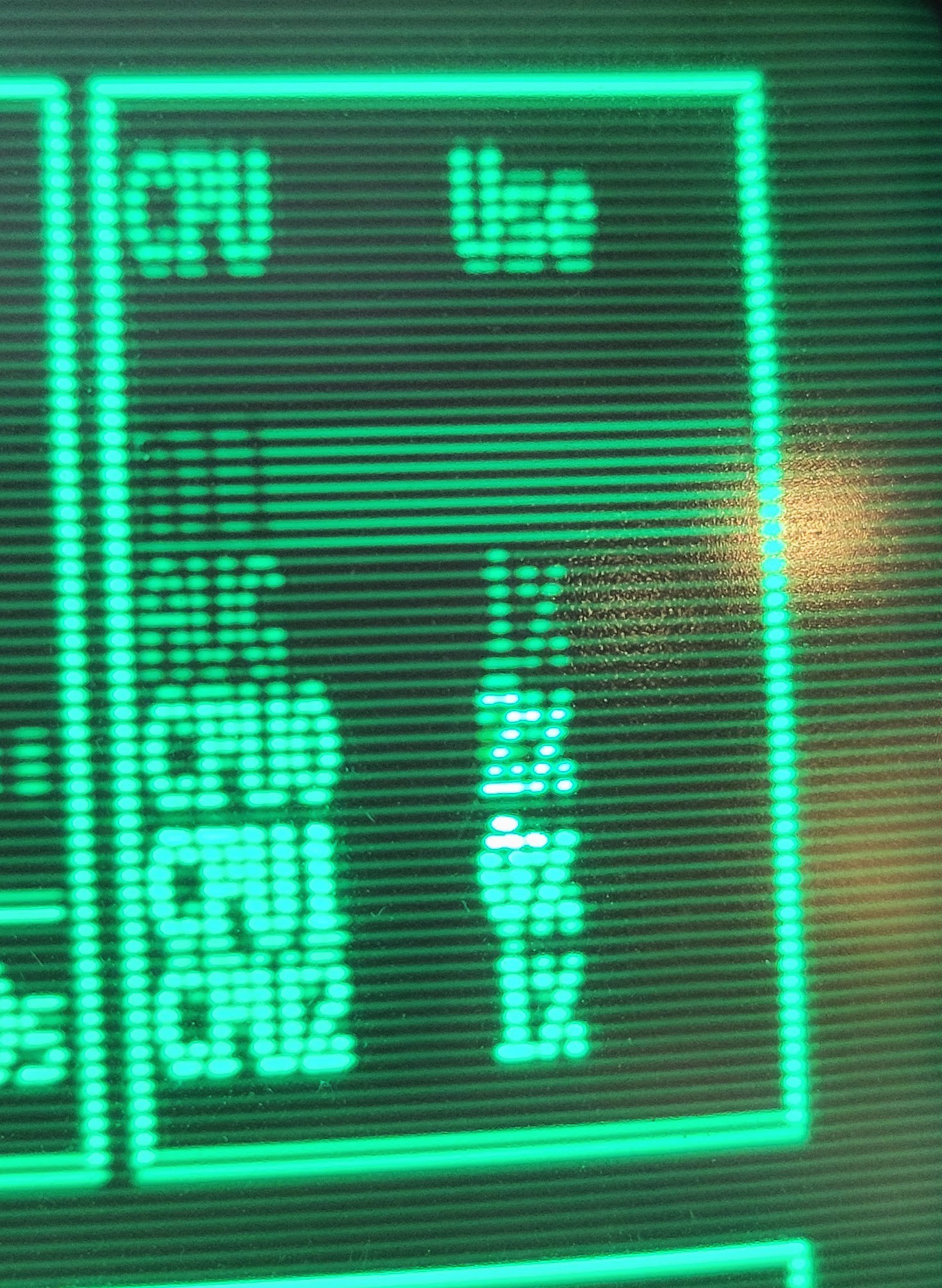
And the avrOS CLI for development and debug.
![]()
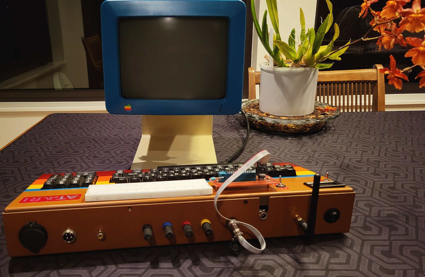
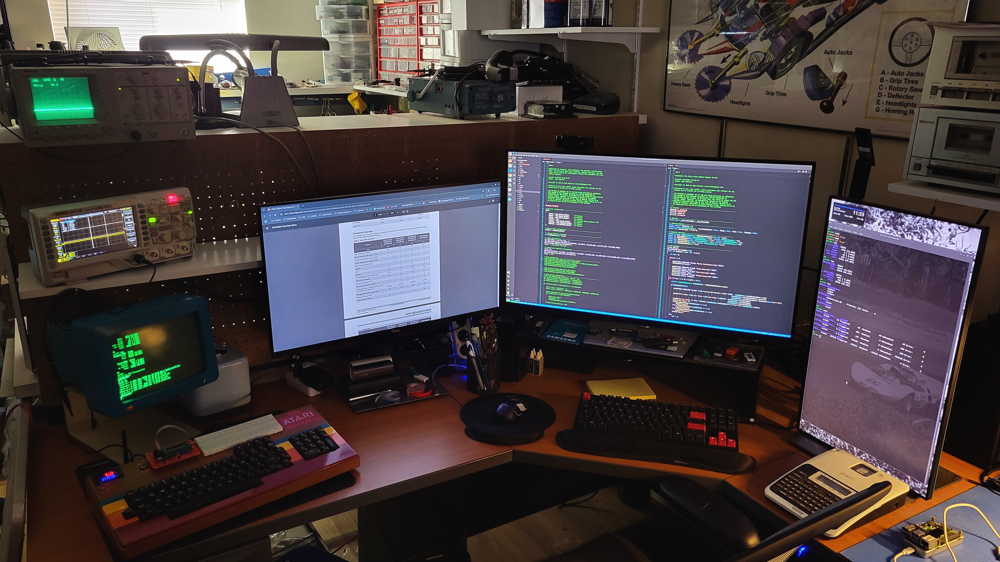
Since this is Linux based and I do 95% of my development from Vscode, I usually remote connect to the Atari workstation from the desktop Linux PC. So, my regular development setup actually looks like this with plenty of modern big LCD displays for browsing part manuals, more than one code editing window and the avrOS CLI on yet another screen.
![]()
-
Making a 40 yr old keyboard work with a PI
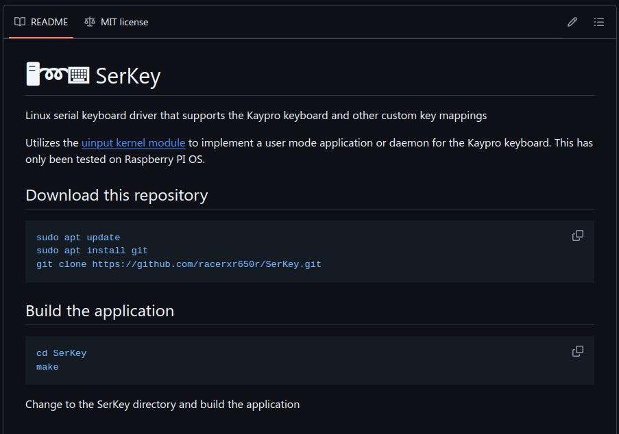
12/15/2024 at 04:07 • 0 commentsTo make the keyboard work with the PI, I wrote a user mode serial driver that uses the uinput kernel module to inject key events to the kernel. I've posted the application to Github. You can find it here: SerKey Serial Keyboard Driver. That was a fun project that required learning about Linux serial port programming and the uinput kernel module.
![]()
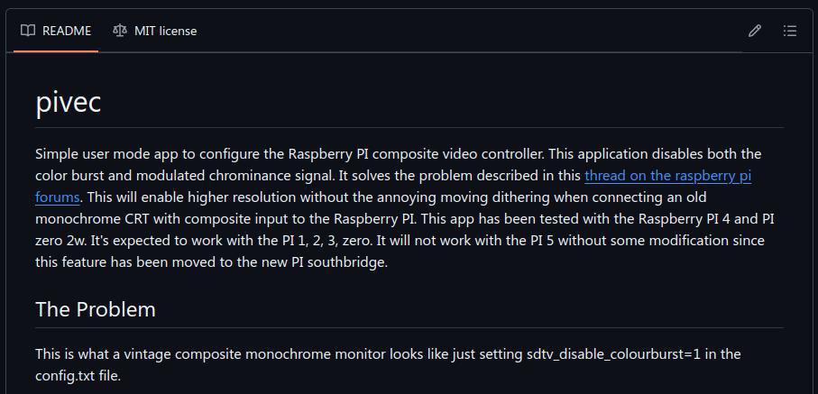
Lastly, the PI supports composite video out. This will connect to and drive the old Apple IIc monitor. However, PI OS does not provide a mechanism to turn off the chroma color signal modulated on top of the basic monochrome NTSC signal. This noticeably degrades the picture quality. So, I wrote another simple Linux command line app to properly set up the PI VEC composite video controller for a monochrome NTSC signal with no color chroma.
![]()
You can see the improvement to the display image below.
![]()
Before
![]()
After
-
Baking a PI
12/15/2024 at 03:57 • 0 commentsWith the keyboard sorted out and the case ready for assembly, I started building, installing, and wiring.
![]()
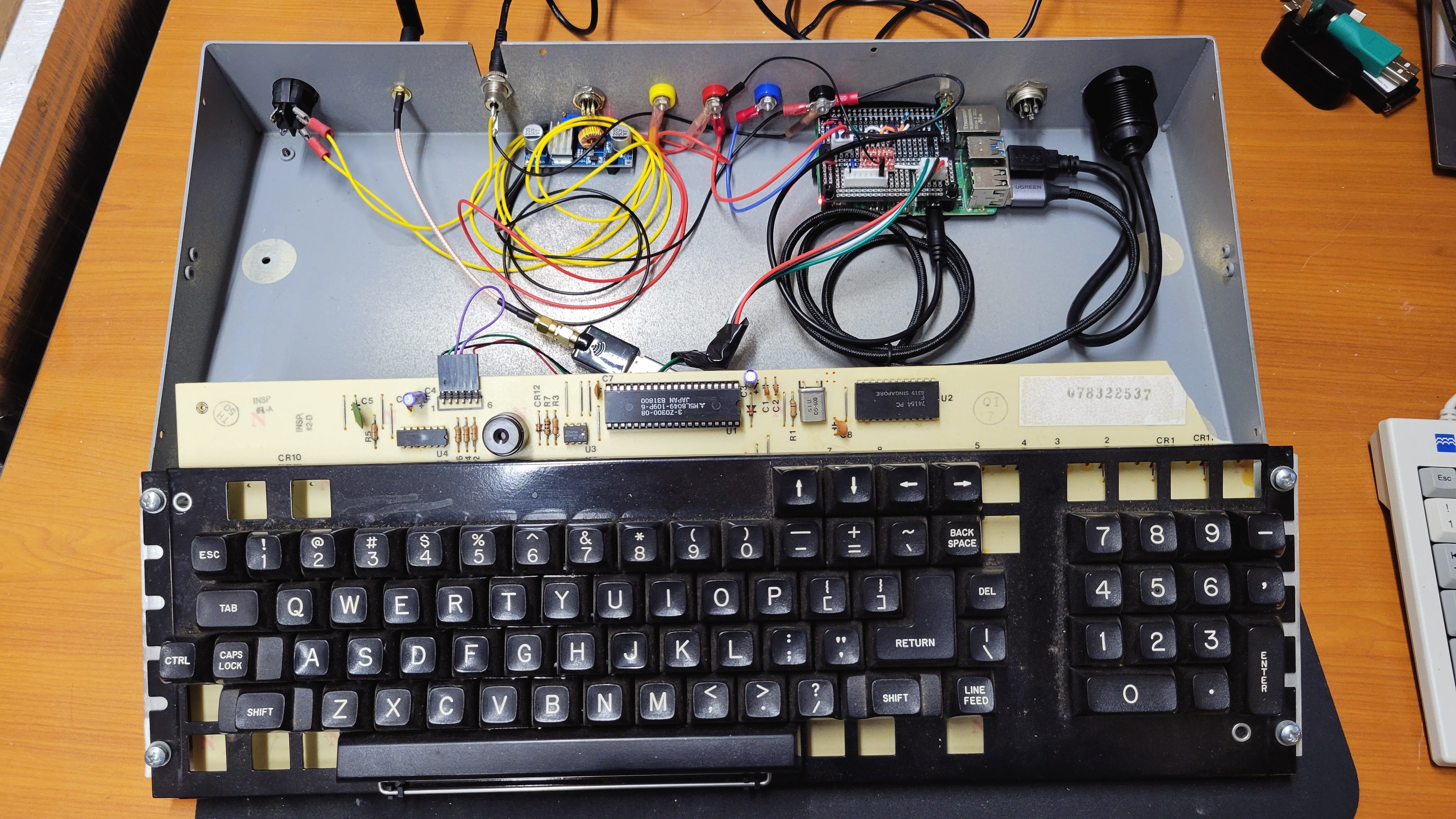
I installed a power switch, 12v to 5v DC to DC converter, banana plugs to bring out 12v, 5v, 3.3v, and ground to be used with the prototyping area, a USB type A port, a 6 pin aviation style connector for the UPDI programming cable w/power, and a SMA WiFI antenna. Next I soldered up a hat for the PI that has a 5v to 3.3v level shifter for the serial lines going to the keyboard and the AVR programming board. The AVR programming board is powered through the 6 pin cable. A toggle switch on the faceplate selects 5v or 3.3v. The PI was installed and wired up. In addition, I plugged in a USB WiFi dongle to make installing the external antenna easier. The PI doesn't have pads to solder an external antenna connector.
Then the keyboard was ready to be connected and screwed back into it's original place in the case. The size of the USB A port on the back panel necessitated that I cut a corner out of the keyboard PCB for clearance. This portion of the PCB had no traces. The USB A port was located there just for that reason.
![]()
-
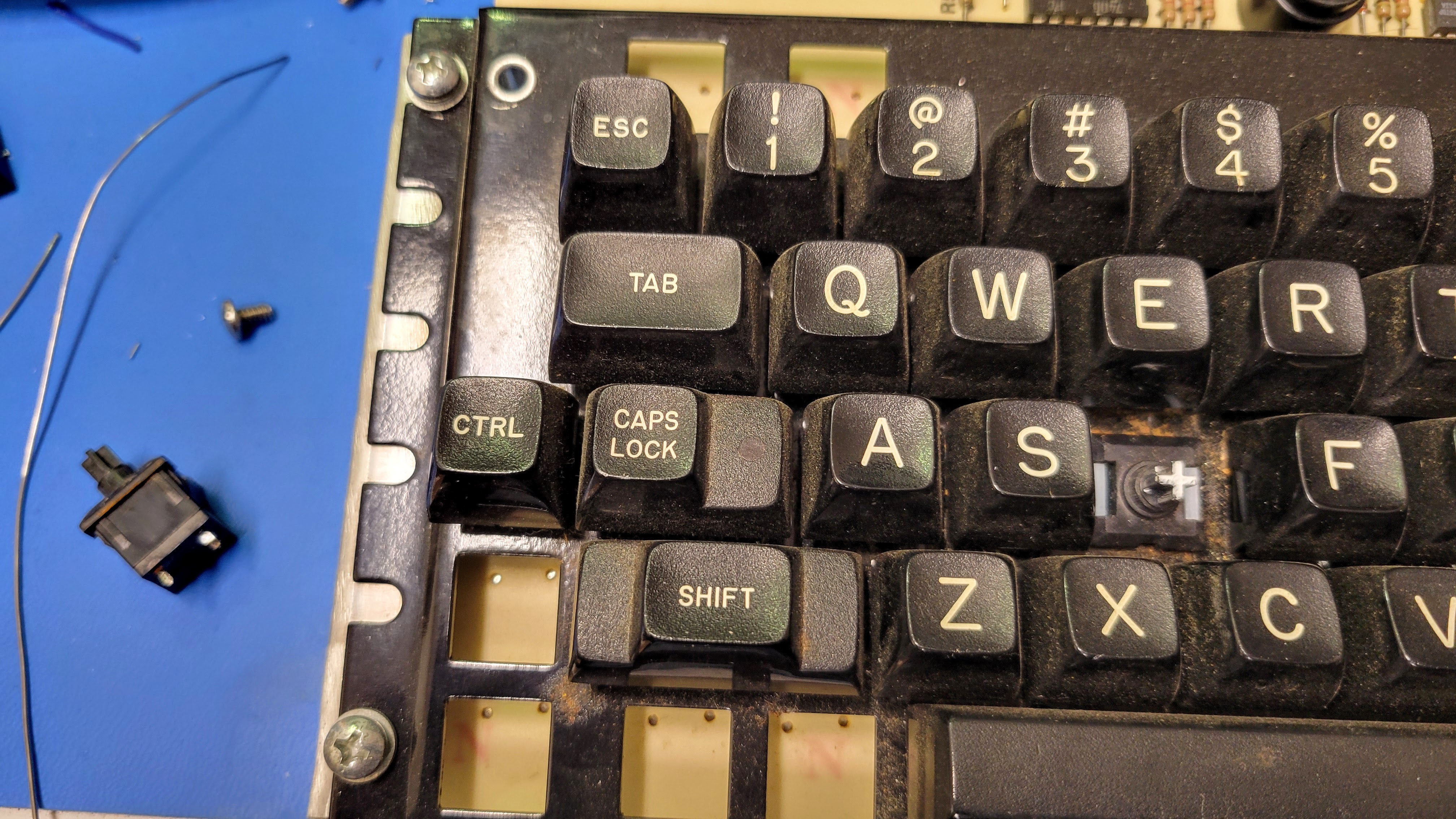
From two there became one
12/15/2024 at 03:45 • 0 commentsAs mentioned, I had two incomplete keyboards. Each was mostly complete with a couple keys/switches broken. Intentionally I had bought two with complimentary keys missing. So, I selected the PCB with the cleanest switches to be the base for the build. I only had to swap three switched. The big through hole parts and my Hakko FR-301 desoldering tool made the work simple.
![]()
![]()
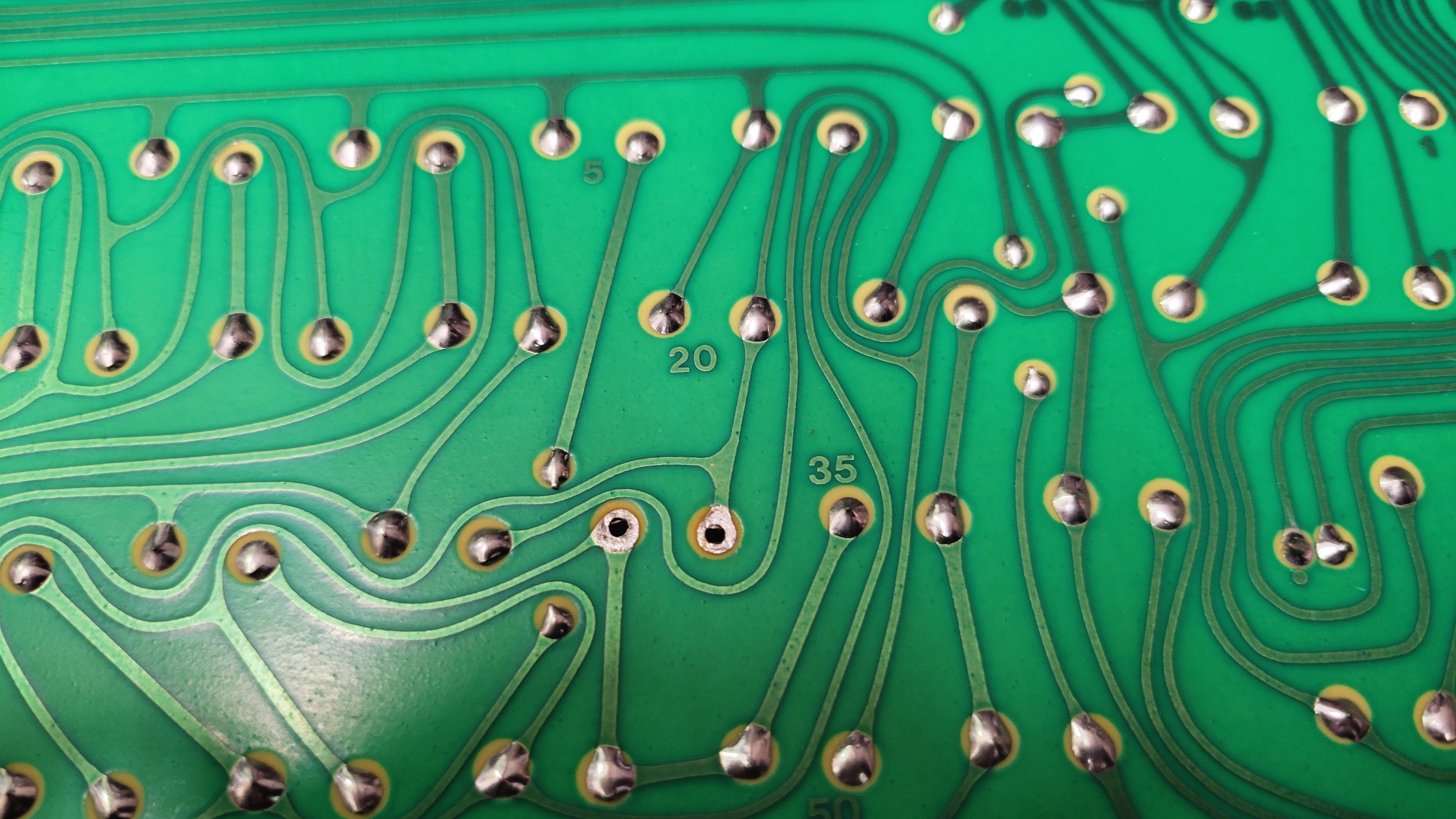
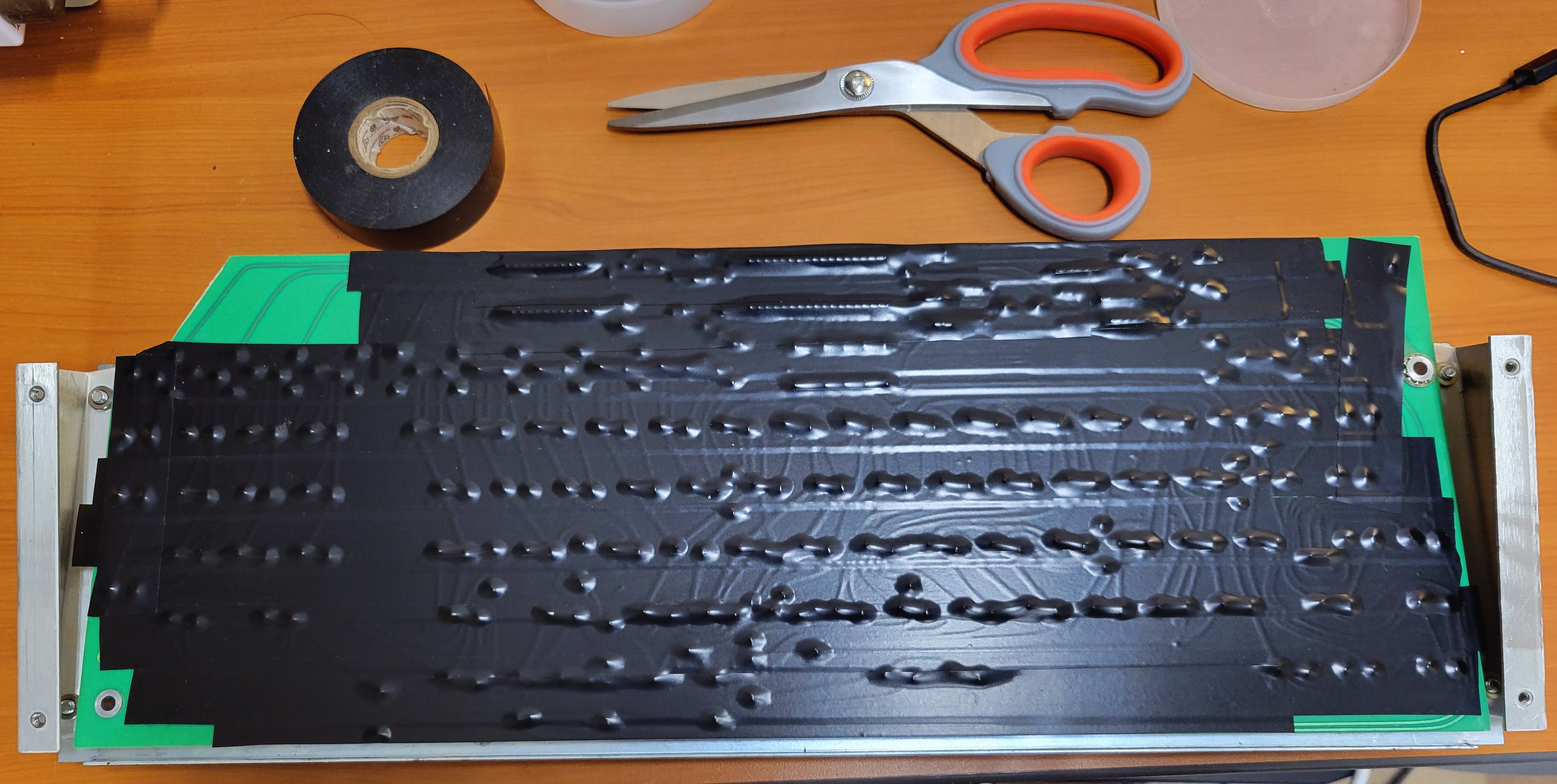
After that, I simply covered the back of the PCB with some electrical tape to minimize the chance of shorting something out since the PI was going to be located below the PCB.
![]()
-
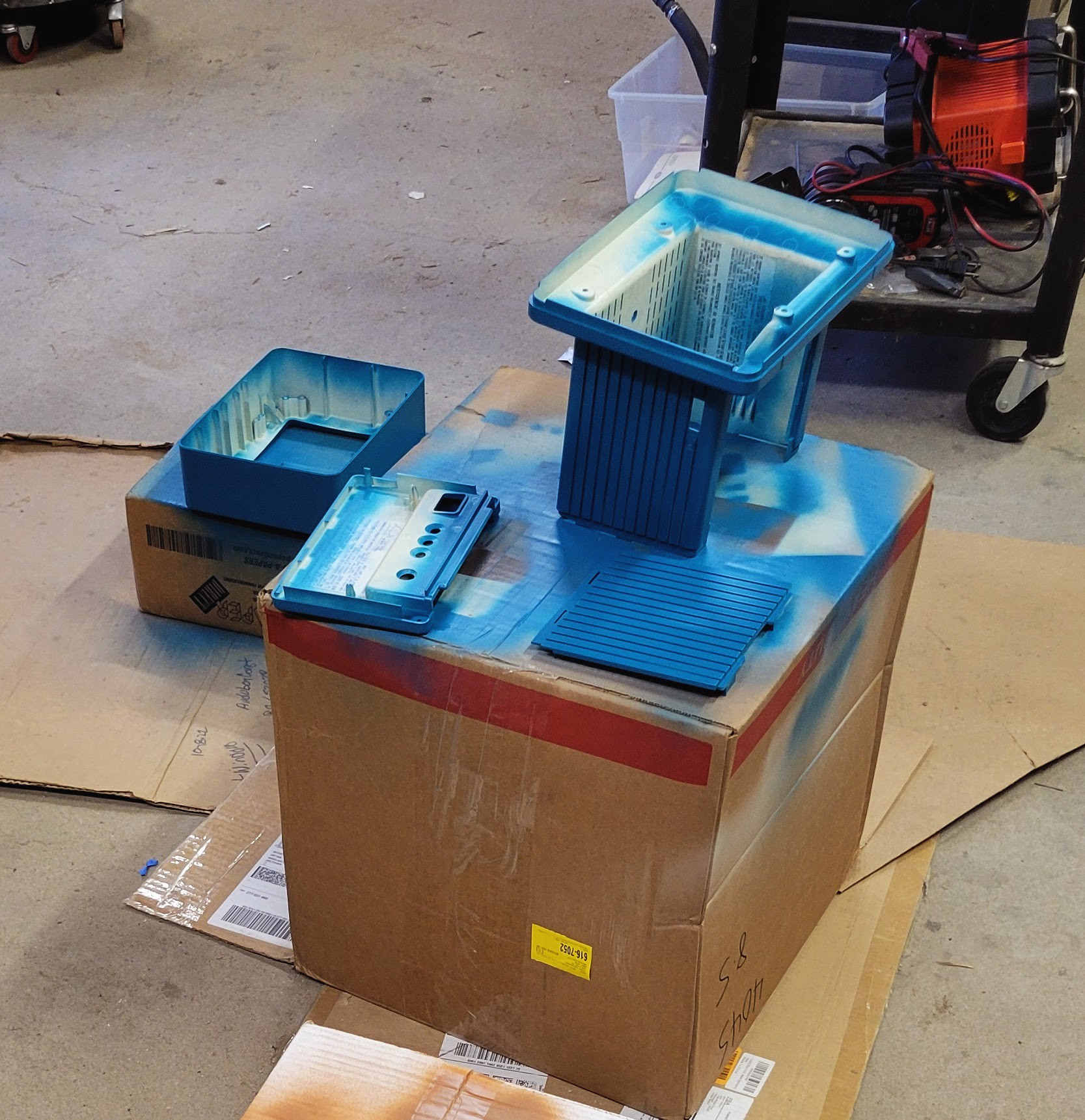
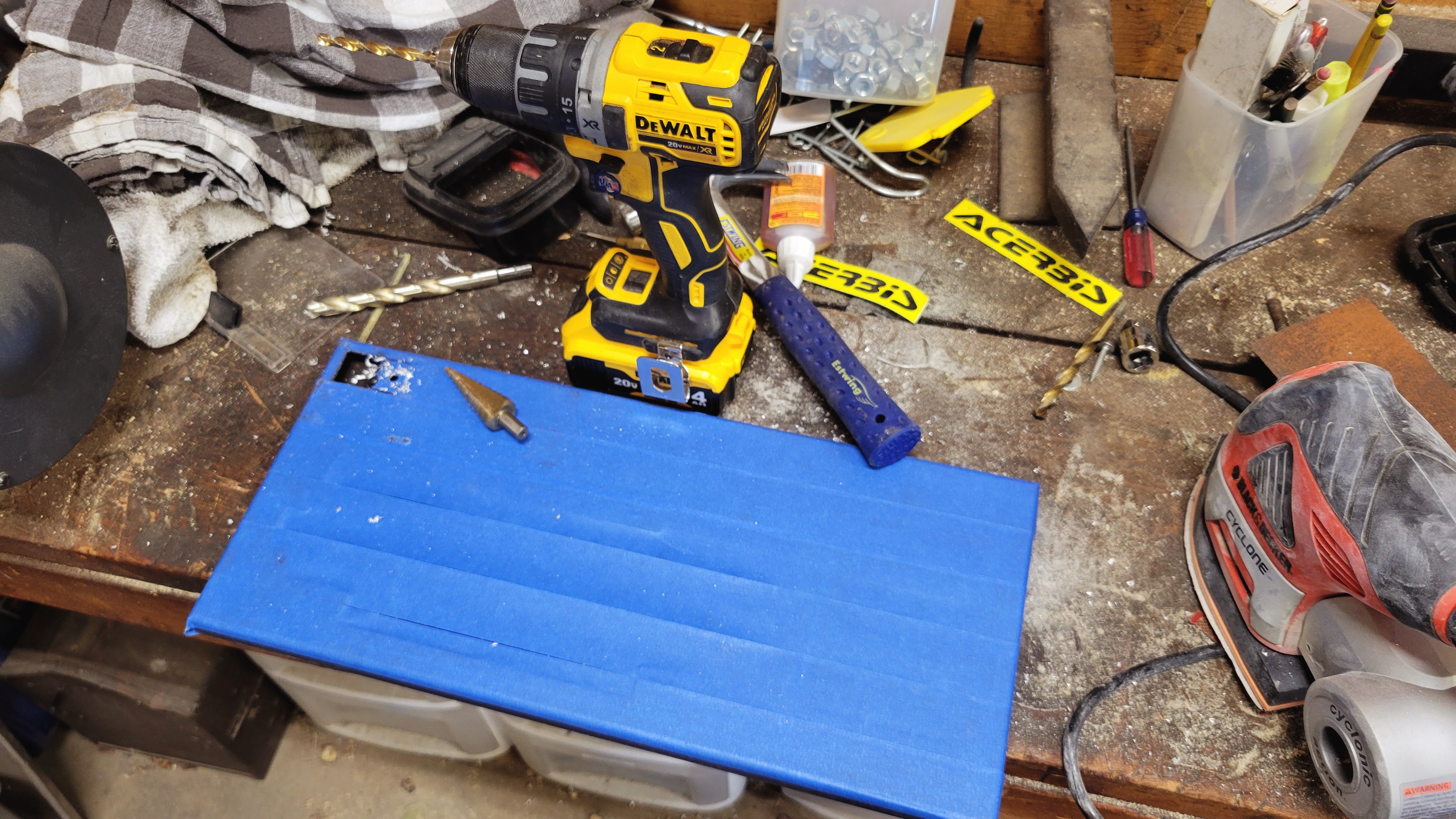
Making it look pretty
12/15/2024 at 03:36 • 0 commentsOnce I measured things and convinced myself everything would fit, I took every thing out of the keyboard case and CRT case and prepped them for paint. For the monitor this just required some disassembly and a little cleaning to prepare it for some rattle can paint.
![]()
A vintage Tektronix like blue that I found at the local hardware store worked well. While I had the monitor apart, I replaced a fuse that had blown (I got it really cheap), cleaned up the pots on the board, and adjusted everything to make the image as sharp as possible. When I was done and it was all reassembled, it looked great.
![]()
Next was the keyboard. That took a little more work. I needed to measure and drill out holes for the PI standoffs, drill holes for the connectors I brought out on the rear panel, drill a couple holes in the faceplate for a couple switches, and cut a square hole in the faceplate for volt/amp meter used to measure voltage and current to the external controller programming board.
![]()
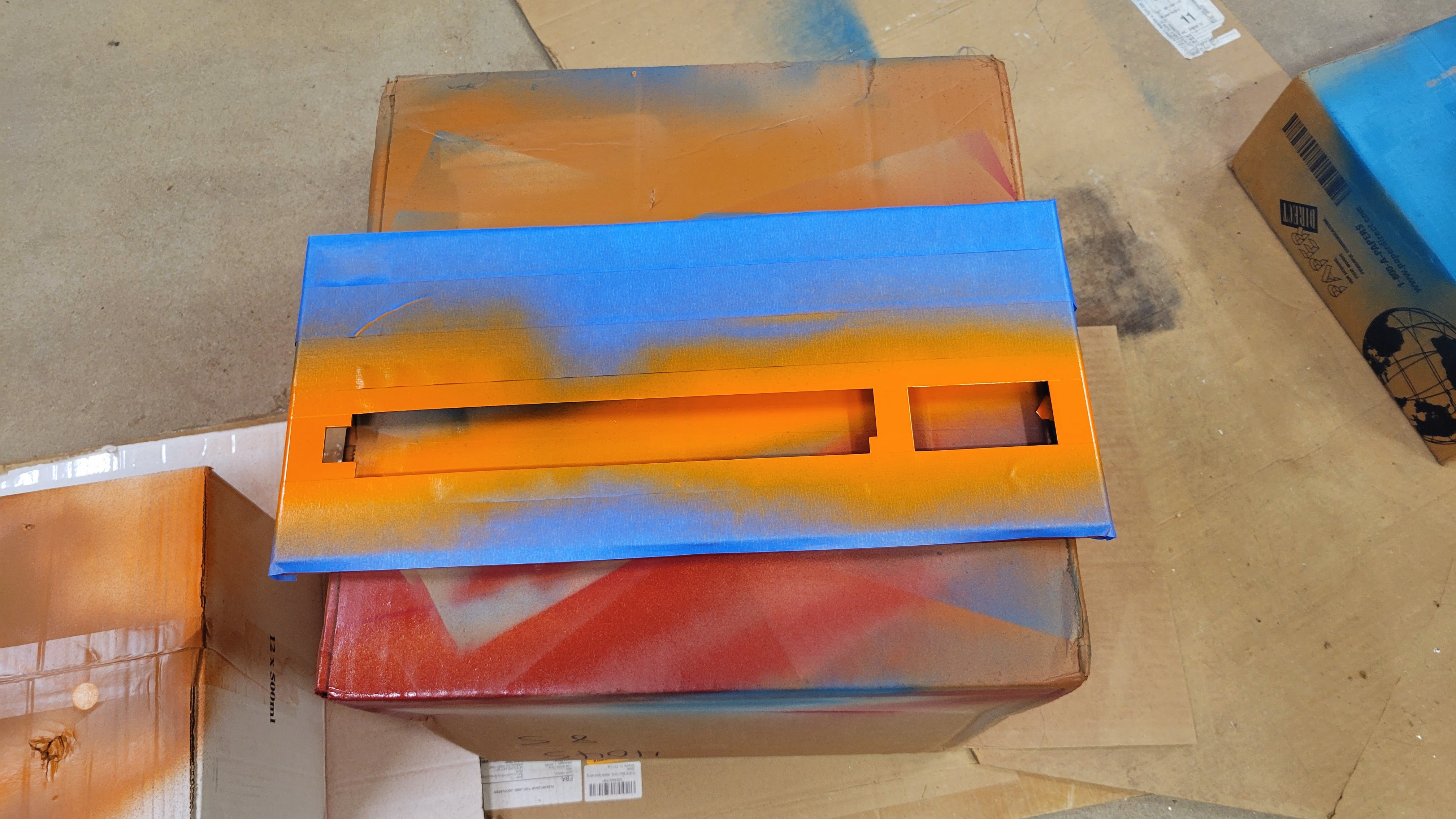
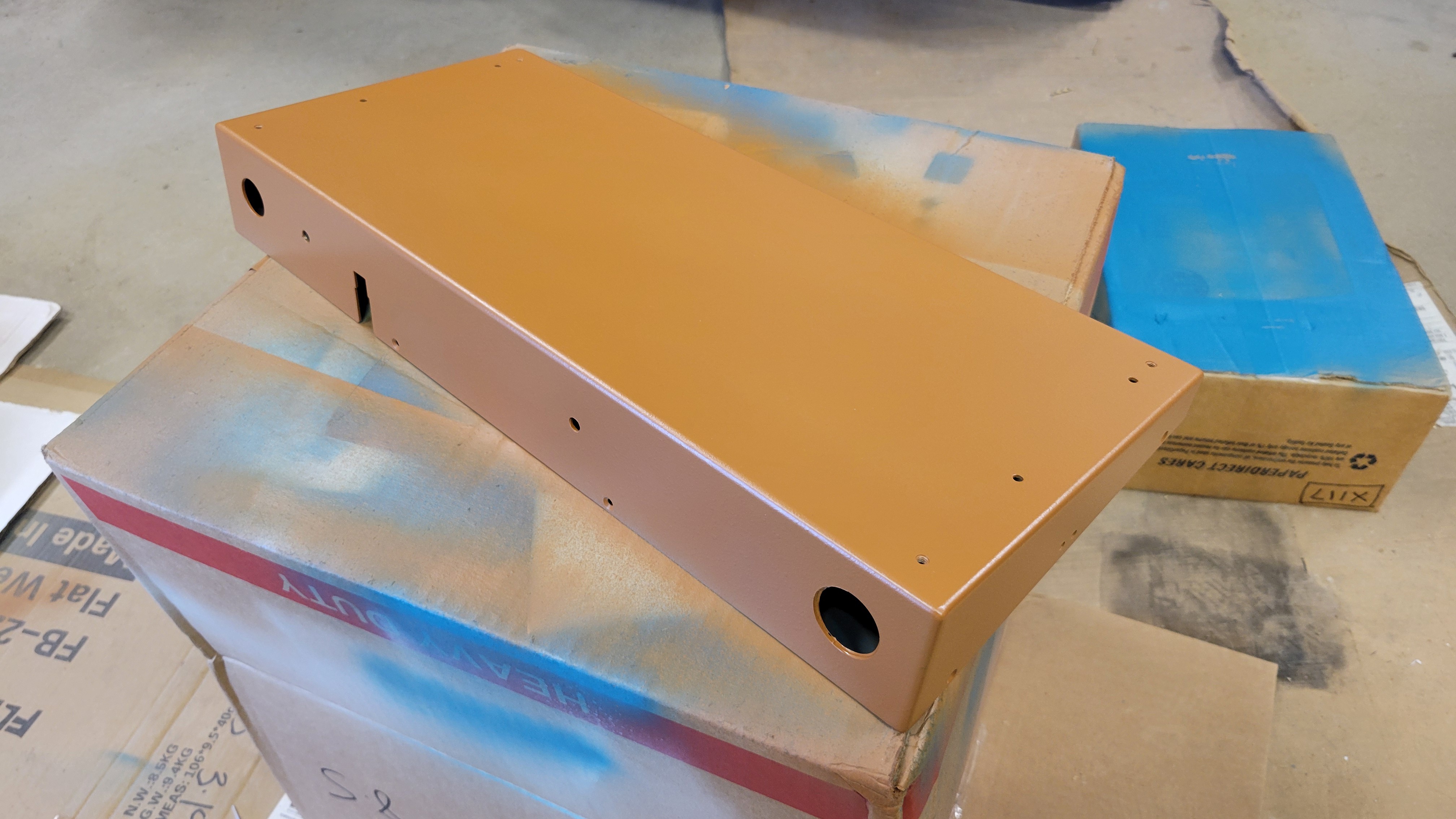
Then it was ready for some paint.
![]()
![]()
For the case, I selected a 70's classic brown base with red, orange, yellow, blue stripes that any 70's van owner would have been proud of.
-
Testing connectivity
12/15/2024 at 03:22 • 0 commentsKaypro sold a couple hundred thousand units back in the 80's and they have been sitting in attics for the past 30+ years now. So, you can find parted out examples pretty easily. In my case, I bought a couple broken incomplete keyboards on eBay very cheap over the last 5-6 years. These were originally intended to be spare parts for a complete system that I came across almost 10 years ago. So when it came time to find a case for a new Raspberry PI project, they were a pretty easy choice.
The Kaypro II keyboard has a 5v TTL level serial connection to the base computer. Digging through old manuals with schematics and specifications, I found that the interface is setup as 300 baud, no parity, 8 data bits, and 1 stop bit. This could easily be interfaced to a Raspberry PI. So I busted out a PI, connected a 5v tolerant USB TTL serial adapter, and fired up tio serial IO app to see what I got.
![]()
It worked first try and I discovered the keyboard sends ASCII characters on the key make. There is not break. For my intended use, that is no big deal. If was planning to build a game machine, that would have been a deal killer.
Connectivity to the keyboard looks like this.
![]()
I connected the PI to the keyboard PCB via the existing 6 pin connector. I reused the original connector from the wire harness. The pinout is in the table below.
Pin Description 1 Power +5v 2 Keyboard TS 3 Ground 4 Ground 5 No Connect 6 Keyboard RX
Atari AVR Development Workstation
A couple parted out Kaypro keyboards and a tired old Apple IIc monitor become a resto-mod late 70s looking AVR development workstation