Ben
Ben-
Project Log: The Final Build - Integrating the Super Widgets ?
08/08/2025 at 10:43 • 0 commentsProject Log: The Final Build - Integrating the Super Widgets 💥
The last few project logs have focused on the subsystems, but now it's time to bring them all together. This log covers the "final boss" of this project: the actual print-in-place process itself. It's one thing to design each part
individually, but it's a whole other challenge to embed them all into a single, complex 3D print while it's still running.
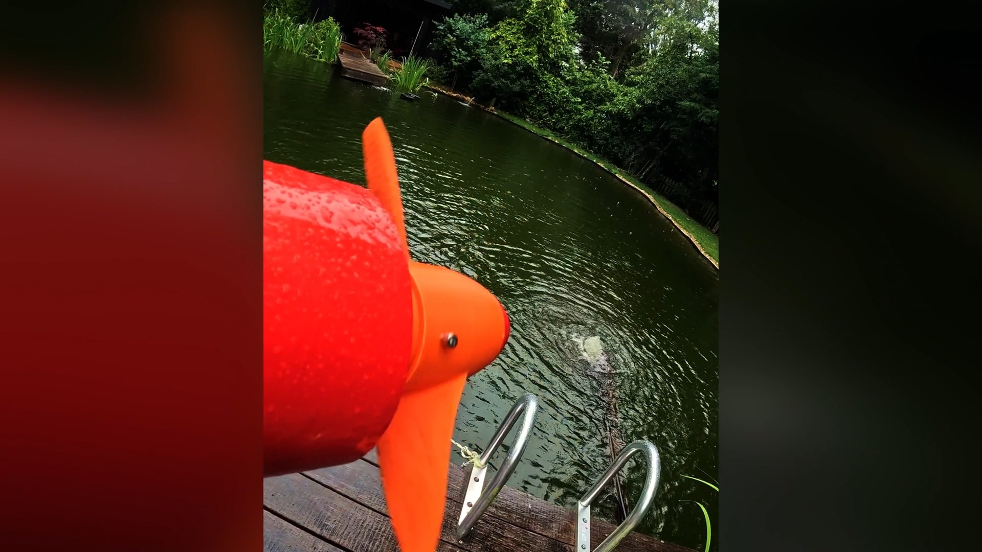
Check out the video below for the Complete build and maiden voyage.
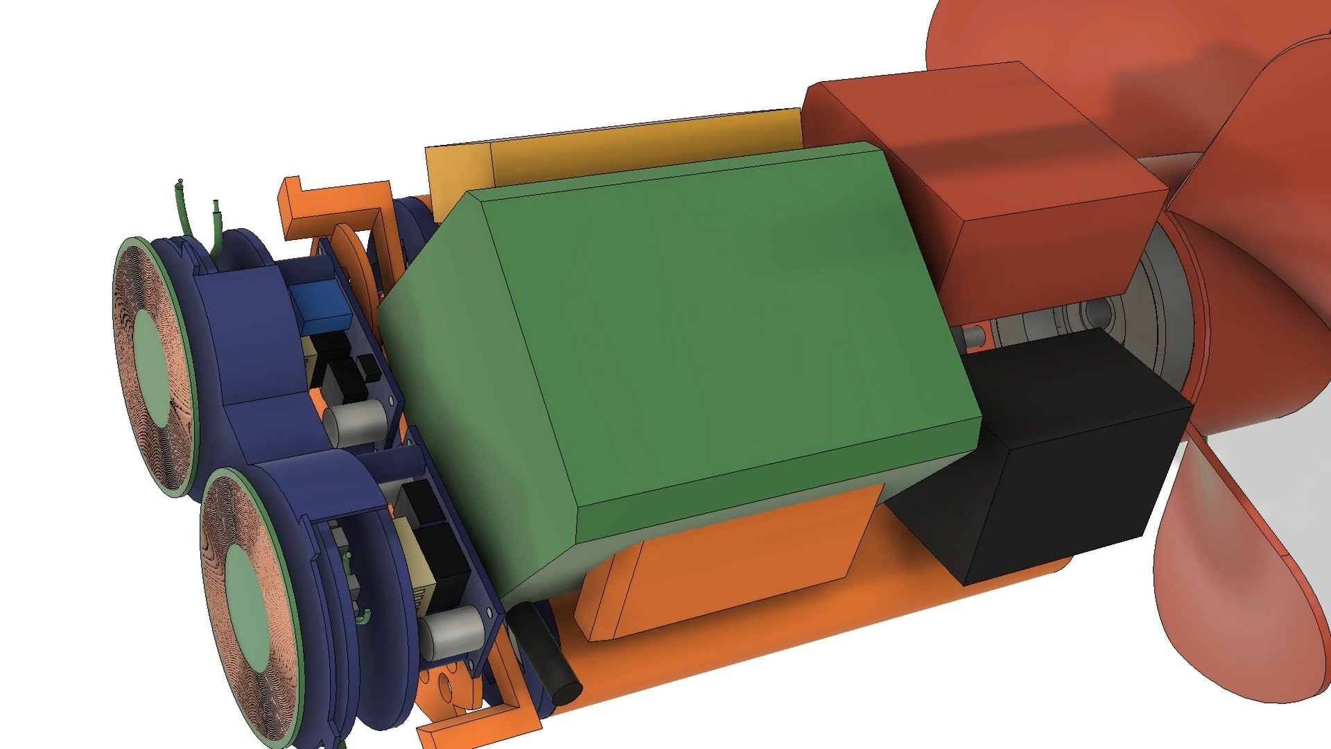
Subsystem Layout and Assembly 🤖
The biggest challenge was fitting everything inside the hull. There was no margin for error. I had to design a layout where each subsystem — the custom battery pack, the wireless charging coils, the motor, and the control electronics — fit together like a puzzle. The custom battery pack, in a 2x4 cell arrangement, was key here. It wrapped neatly around the drive motor and served as a central "scaffolding" point for all the other components. Custom-designed standoffs and mounting tabs were integrated into the hull's internal structure to ensure each part could be accurately positioned and secured during the print.
![]()
The Print-in-Place Process: A High-Stakes Assembly 😲
The final print was a nerve-wracking, 14 hour affair . The plan was to pause the print at specific layers to insert the "super widgets" and then resume printing.
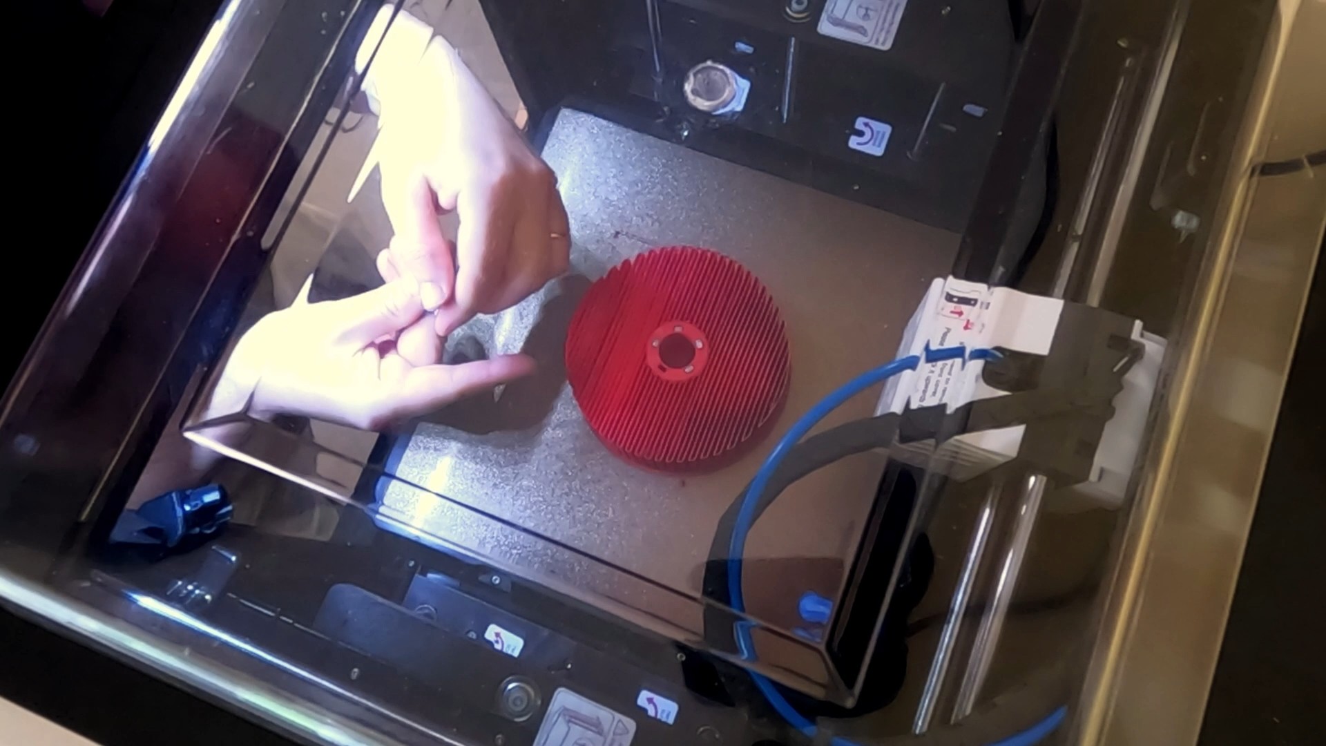
- Embedding the Magnetic Gear's Concentrator: The first pause was to embed the iron bars that form the field concentrator layer of the magnetic gear. This was a relatively simple step, requiring a bit of glue to secure the bars in place.
![]()
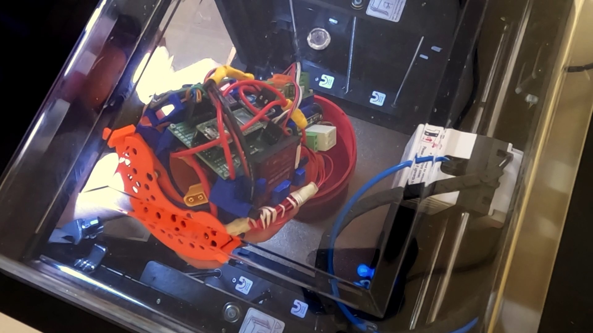
- Inserting the Drive System: The next pause was for the largest component: the complete drive system, including the motor and internal rotor. I had designed orange tabs on the drive system to mate with the hull's walls, ensuring perfect orientation. As I lowered it in, the weight of this massive component slightly lowered the print bed due to elasticity in the Z-axis belt. I had to manually adjust the Z-offset by 0.3mm to prevent the nozzle from hitting the newly inserted part and causing a print failure.
![]()
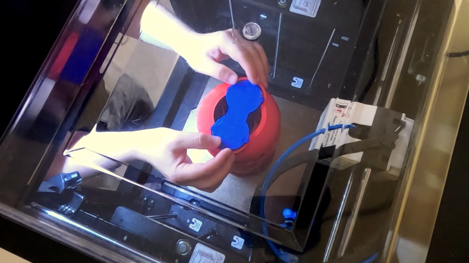
- Adding the Wireless Charging Coils: The final pause was for the wireless charging assembly. I connected it to the battery, lined it up with its tabs, and tacked it in place. Again, a small Z-offset adjustment was necessary to keep the print running smoothly.
![]()
The print finished successfully, leaving me with a completed hull and all the internal systems encapsulated. The last step was to coat the exterior in epoxy, and the impossible print-in-place sea scooter was finally a reality.
![]()
- Embedding the Magnetic Gear's Concentrator: The first pause was to embed the iron bars that form the field concentrator layer of the magnetic gear. This was a relatively simple step, requiring a bit of glue to secure the bars in place.
-
Designing the wireless charging and battery system
03/21/2025 at 12:14 • 0 commentsIn this post It’s time to focus on the wireless charging and battery system of the sea scooter.
If you are interested the below video documents this stage of the build. So please do check it out!
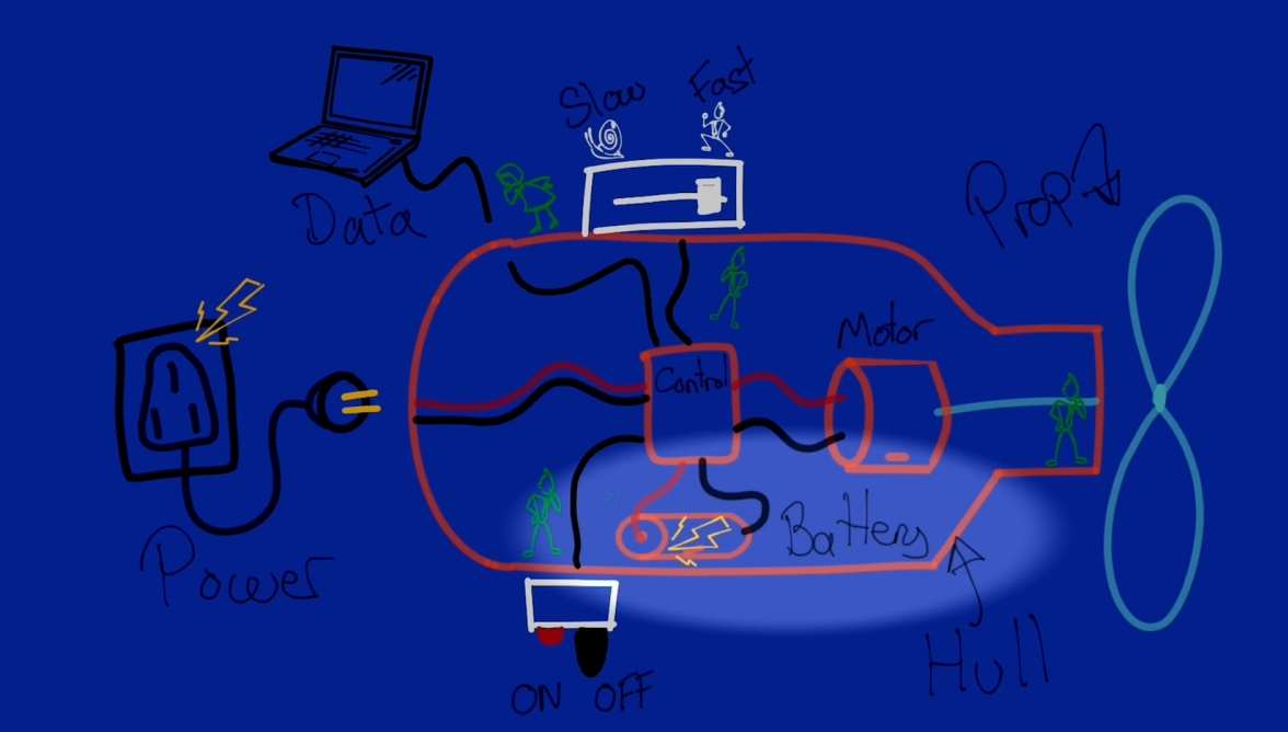
What is the power system
I've broken the power system down into 2 main subsystems.
1 – The power storage subsystem. Comprising of a battery pack and battery management system.
![]()
1 – The power storage subsystem. 2 – The wireless charging subsystem. All about efficiently getting enough power at the right voltage though the hull wirelessly to charge the batteries in a reasonable time scale.
![]()
2 – The wireless charging subsystem.
Designing the power management subsystem
I first takeled the design of the power management system as this will have a knock on impact to the wireless charging subsystem design. The first decision was what voltage and maximum current I want the system to run at. If you’ve followed the previous instalments of the build you might know the answer.
Quite early on in the build I decided to design the system to run at around 24 volts with a maximum 15 Amps current draw on the basis of the characteristics of the motor and it being still a safe voltage to work with.
To calculate the Watt-hours capacity. I’m going to approximate the power consumption as the maximum expected power consumption of the Motor. Following the results of the magnetic gear propeller testing I arrived at a max current draw before the magnetic gear stalled at around 4 amps. So I’m going to work on the basis that the max average power consumption of the sea scooter will be 4 amps. So the total power consumption would be voltage times current so 24 times 4. Lets call it 100w.
The next question is what is the minimum time I want the scooter to run for on a full charge?
I think anything under 30 mins would be rather frustrating so i've picked that as the absolute minimum run time. Which if it’s running flat out at 100w would consume. 100 times 0.5 which is 50 Watt hours of capacity.
I've decided to design my own battery pack that will snugly fit into the hull. It will be a fun mini project on it’s own.
Right so given that I’m making my own battery pack the first thing to decide was what battery chemistry do I want to use. As this would affect the way that I’d have to wire the battery up, volume and storage capacity, also the charging circuit.
To cut a long story short I ended up deciding on LiFePO4. Principle on the basis of high energy density. High discharge rate. one, if not the most stable of the mainstream Li-ion battery chemistries. Modular form factor. And..well.. I found a job lot available at a really good price on eBay. :-)
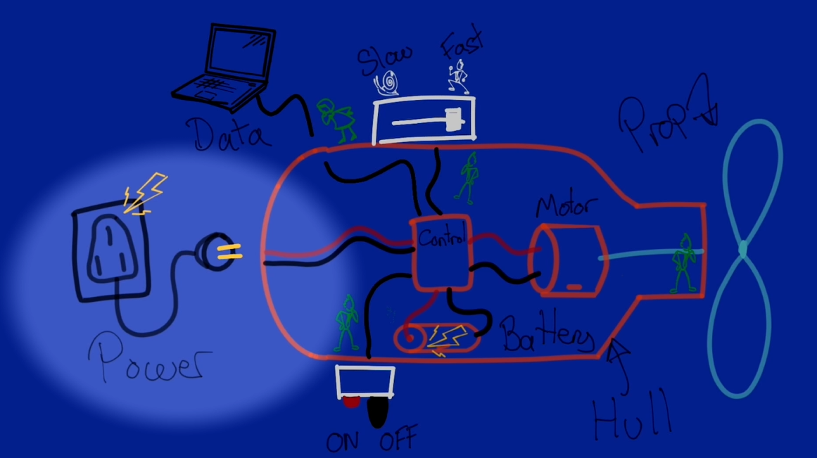
This is what a single LiFePO4 cell looks like.
![]()
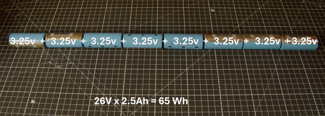
There are a few common form factors you can by the most common is called a 18650. Which means that it is has an 18mm diameter and 65 mm long. This one is actually a 26650 which, as you've probably guessed, it means it’s got a larger diameter of 26mm and a length of 65mm. These batteries have a nominal voltage of 3.2 v. Which is importantly is different to the 3.7 volts per cell your probably used to if own a LiPo battery for an RC car or plane. These one’s have a capacity of 2.5 Ah and a somewhat unnecessarily high discharge rate rating of 42 A. Apparently they were originally spec to go in an EV car battery. I think I paid around $3 per battery.
Ok so I’ll need a battery that runs at around 24 volts.
We can increase the voltage though the magic of simply connecting the batteries in series
![]()
Ok so 8 cells is the magic number to get us over 24 volts. So this battery configuration would give us 26 volts times 2.5 amp hours equals 65 Wh of energy storage capacity. Which should give us a minimum of 40 minutes run time under normal conditions, so more than the 30 min minimum run time I was aiming for.
So it looks like this battery pack that I will need to build will need to be wired as an 8S 1P battery pack or in other words an 8 cells in series and 1 set of cells in parallel.
One of the down sides to Li ion batteries is that they are fairly fussy about what voltage they are being charged at and discharged to. If you go outside of this range they start degrading rapidly and in extreme cases might case the battery to become unstable and even catch fire.
To ensure that each and every battery cell is being maintained within the required voltage range when operating a key component of any Liion battery is some sort of battery management system, often simply referred to as a BMS.
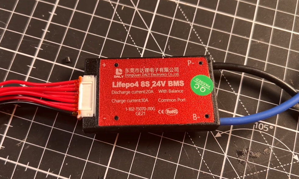
After searching around I eventually decided to go for one made by the relatively well known Chinese company called Daily BMS that sits towards the bottom end of the market, but cater for just about all battery configurations and most importantly LiFeO4 chemistry. As the min and max voltage range is 2.3v to 3.65v compared to most other Li ion chemistries you’ll typically see that are 2.7v to 4.25v.
![]()
This one is an 8S 24v, well i've already mentioned that it’s really more like 26v nominal and if we want to charge it to 100% then we’ll actually need to supply 29.2 v! It’s spec’d for 20 A continuous discharge and 10 amps charging which should be plenty for this system. And it apparently also have a sort of last resort over current protection for both charging and discharging current limits.
You can see that it comes with quite a few wires. That’s because each cell-string in series needs to have its voltage individually monitored. Since I only have one cell in each string this makes it a little easier.
Designing the enclosure.
Great so we know how the battery pack needs to be wired now lets design something that will fit snugly into the sea scooter hull, in the gap between the motor and the hull. I think 2 cells by 4 should be pretty efficient packing so will go for a crescent shaped outer battery holder, that has a base plate to followed by 4 battery’s then a spacer between the cell layers so that I can attach the BMS monitoring cables, then another 4 cells and finally a lid. I think that looks pretty compact.
![]()
Assembling the battery pack.
I first added some battery terminals to the blue top middle and bottom parts. Then solder on some thick gauge wire to create a path from the first cell to the last to give us our 8 cells in series. Then solder on the BMS cell monitoring wires to each of the positive terminals of the cells plus an initial ground. Then solder on some thick gauge wires to the Positive and Negative terminals.
The BMS then sits between the negative terminal of the battery and the negative wire of the external charging or discharging systems. With the positive battery connected straight to the external system.
![]()
Ok so on to the Wireless charging subsystem
Great so now we know what the vital statistics for voltage, current and capacity parameters for the power management system to design and source a wireless charging system to feed it.
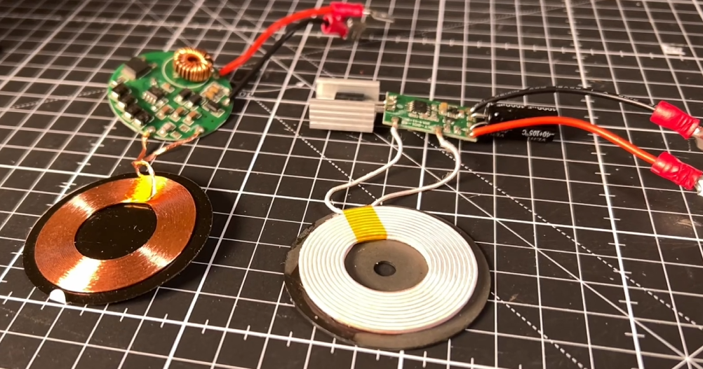
After doing a bit of research I think a resonant inductively coupled wireless charging system should give the best bang for my bucks. Very few that I found actually even quote an output current. But this one seemed to be the best output power to size to cost balance. Apparently It’s got an input of 24 v and an output of 12 v delivering up to 2 Amps. Which would give me up to 24 Watts of charging capacity.
![]()
Ok now lets tackle the output voltage as we need 29.2 v to charge the batteries to 100%.
To do this I’ll add a boost converter. Which has a sole purpose to take an input voltage and step it up to a higher voltage. And I can use little blue trimmer component adjust the output voltage. I think these where about $1 each and supposedly handle 3 Amps and boost up to 35 volts.
![]()
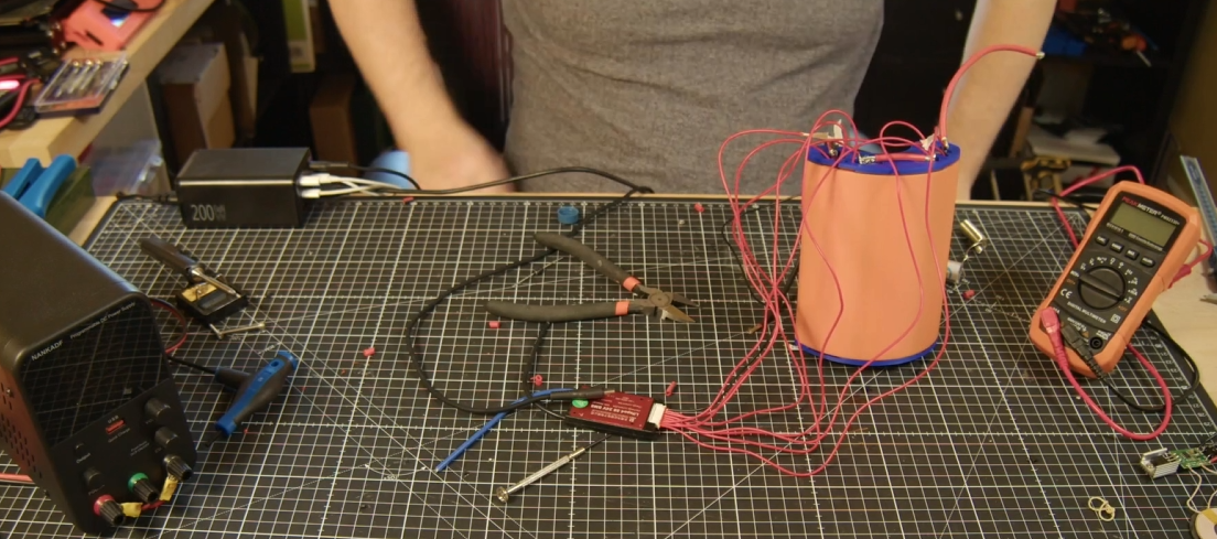
And after quite a bit of testing. I ended up settling on the below design. which uses multiple wireless charging coils. (see the video at the top of the post for details).
![]()
which ended up being able to charge my 26v LiFePO4 pack at 1 Amp as you can see in the below picture which should be plenty of power for this project!
I shall call that a success. :-)
If you are interested the below video documents this stage of the build. So please do check it out!
-
Designing an underwater wireless control system
03/06/2025 at 14:43 • 0 commentsWhat is the control system
So I've been continuing to focus on meeting the second design constraint . Working out how to wirelessly control the sea scooter…. underwater.
if your interested in the detail of this phase of the project then you might want to check out the video below that goes though it all
I've broken this down into 3 subsystems.
1 - The master on off switch or ‘key’. Which isolates the power source from the rest of the system. Reducing the passive current draw when the sea scooter is of as well as providing an emergency off button that is triggered in the event the sea scooter gets out of control, say you let go of it while underwater
2 – the throttle and axillary function to make the sea scooter change spend and trigger any other auxiliary functions that we might want to do periodically such as synchronising the sea scooter with a base station or running a special test program.
3 - the sea scooters ‘brain’ or central control system that takes in inputs and concerts these to output signals to control other systems like the motor.

Video explaining the three subsystems I've focused on in this part of the build Why can we just use Bluetooth or wifi..
When someone say’s that they want to make something wireless the first thing that comes to mind is why not use wifi or Bluetooth to achieve this. I mean they are pretty main stream technologies and seem to be integrated into just about anything.
the first thing to note about WiFi and Bluetooth is that these both work at 2.4GHz and higher frequency, which is the same as a microwave oven. This is because it’s a frequency that water is very good at absorbing and turning this into heat.
So when you try to send a Wi-Fi or Bluetooth signal through water, which is often about ten thousand times weaker than your microwave oven the water molecules almost immediately absorb this radiation and converts it into heat. Not very useful.
So if you work it though Wi-Fi and Bluetooth have an theoretical range of a few of millimetres though water. And as everyone I’m sure knows trying to use wifi or Bluetooth at the extreme of it’s range is often rather flaky and not something you can particularly count on.
So I've gone for something a little different and once again turn to the power of magnets to save the day. As interestingly the magnetic permeability of water is almost the exactly the same as air. So I've designed a control system that can sense magnetic fields above a certain threshold at a particular point in space so that I can transmit the intention to switch a button or increase a throttle.
Sensing magnetic fields is of course something that is not a new idea and there are quite a few ways to achieve it. Two popular, simple and well proven methods are firstly using a reed switch. Which acts like a magnetic switch that closes when a magnetic field is near . The second method uses a hall sensor to sense the strength of the local magnetic field.
Both sensors have their advantages.
The reed switch is super simple but only giving binary feedback of whether a magnetic field above a certain threshold is nearby, but consequently fairly robust to changes in the local magnetic field due to other sources of magnetism such as the motor, magnetic gearbox even the earths magnetic field.
While the hall sensor can sense the size of the magnetic field as well but this requires more complex electronics and often benefits from being connected to a microcontroller to read the output from the sensor and decide what to do with the signal. Hall sensor are much more sensitive than reed switches, which is great, but this also makes them more susceptible to magnetic noise from other sources of magnetism that are in the local area.
On this basis I’m going to for now at least make the master on off switch a reed switch. As I want it to activate independently of any other electronics and have a high threshold for being affected by other changes in the local magnetic field to maximise it’s reliability.
For the throttle and auxiliary function control. I actually tried both reed switches and hall sensors and ended up for now at least sticking to one based on reed switches. If you are interested I've included the details of why, backed up with some testing results, in the main video at the top of the post.
The control system design
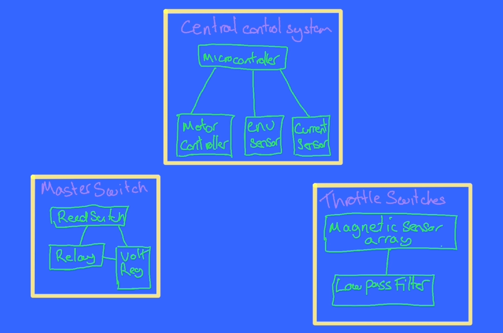
Right so we’ve got our three subsystems, lets start to flesh the design out a bit.
Lets start with the sea scooter brain. – we’re going to need a simple computer, lets use a microcontroller as the brain. In addition to the two other input control systems we’ll need to out put a signal to drive the motor, to help with this we’ll need a motor controller that can drive the high voltage DC motor which in turn drives the propeller.
If this build goes to plan we’re going to end up with a hermetically sealed chamber it’s going to be important to monitor what the environment of the chamber is during operation. Specifically I think it’s sensible to monitor temperature to check that heat is able to get out of the system quick enough, the humidity to check it’s not leaking and the pressure of the chamber to check that it’s not going to pop and also as an indirect measure of how air tight it is when it goes under water and whether their might be a slow leak of some kind. Lets call this an environmental sensor.
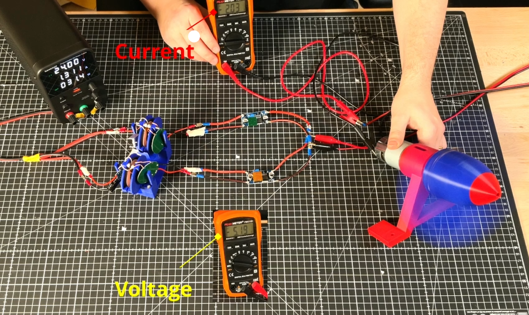
![]()
In addition I mentioned in the previous Hackaday Log post that when we add too much torque though the magnetic gear it looses synchronisation. And this synchronisation loss seems to correspond to a fairly consistent current draw from the power source. I therefore also need a current sensor to monitor how close the magnetic gear is to it’s limit as well as detect if synchronisation is lost so that the motor can back off and let the gear regain synchronisation.
For the master switch sub assembly as well as the magnet sensing reed switch I've added a relay that it can control to handle the larger current that the master switch will need to handle and to ensure the master switch is able to function on it’s own we’ll also need a voltage regulator just for the master switch sub system that can work off the raw 24 volts battery supply and step this down a more civilised 5 volts to drive the relay.
For the throttle and auxiliary sub system were going to want to ensure the signals that are coming out if the subsystem are as reliable and accurate as possible so lets add a filter to remove as much of the unwanted noise that could be created by the environment that the magnetic sensors or switches are in. As a first go i've added a low pass filter to the output signal from these sensors to filter out the high frequency sources of noise and only measure the relatively slowly changing states that would correspond with say pushing a throttle leaver.
Ok so I know logically what I want to build lets see what this looks like in terms of electronic components on the bread board .
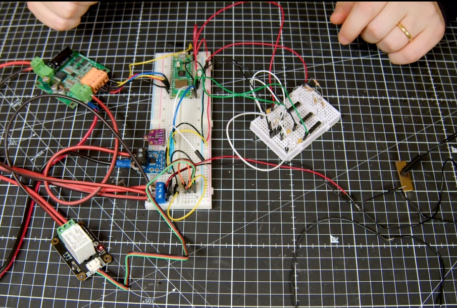
Bread board
![]()
For the brain I’m using a Raspberry Pi Pico W. this is connected to a bme680 environmental sensor and ina260 current sensor via an I2C bus.
The master switch uses a waterproof reed switch connected to a L7805 5 V regulator steps down the 24 v raw battery supply to drive a 15 amp relay.
For the motor controller I’m using a 15 amp single channel motor controller that can handle 36 volts. Usefully it also has a 5v output that I can use to power the microcontroller and all the other low voltage circuits. You can see that the current sensor is inserted between the motor controller and motor and you might be able to make out that it’s sensing the low side current i.e. on the ground side rather than the high side as high voltage PWM drive signal produces far too much electronic noise to be operated in the vicinity of the low voltage logic. As soon as I tried to measure the current using the high side configuration above about 15 volts the sensor stopped working.
The throttle and axillary control system design based on reed switches. uses a series of equally spaced reed switches that each incorporate an Resistor and capacitor to create an RC low pass filter. As the magnet passes over the reed switch it is activated. It’s actually possible to have more than one reed switch activated at any one time so allowing us to interpolate the magnets position as well.
For approach two that uses hall sensors I’ve mounted two hall sensors on the PCB so that they are in the same plane. As the magnet moves over them the relative magnetic field that is sensed should change fairly repeatably.
It will be interesting to see how they compare.
Proto board
So you can see that the bread board seems to be wired up correctly and working as expected. Lets transfer this onto proto boards so that I can integrate them into the test hull.
Much soldering later.

Finished throttle and aux wireless control board based on reed switches 
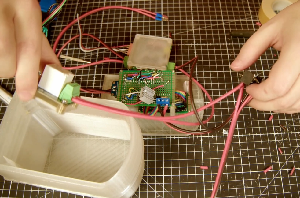
finished main 'brain' control board that include the master reed switch components Design and build the casing.
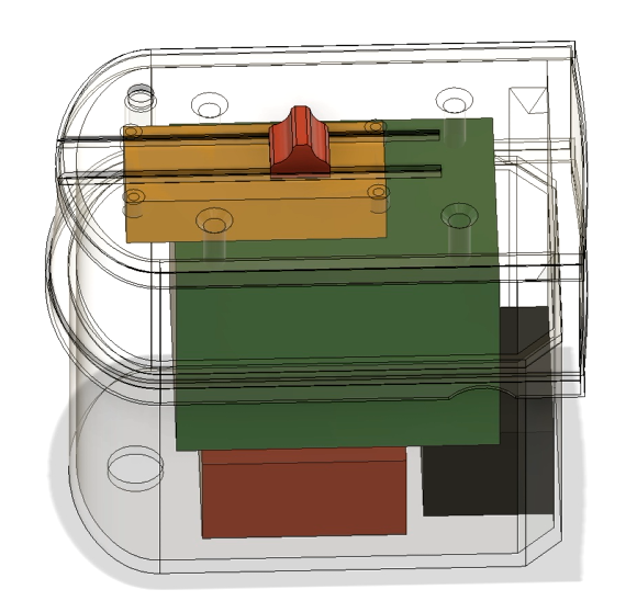
Right so next step was to work out how to fit all these electronics into the test hull so I could do some in water testing.
![]()
For this I created a case that fits on top of the test hull and can double as a replacement for the polycarbonate lid. I added add some rough bocks for each of the pcb’s in the CAD model to make sure we can fit everything inside. On the lid I’ve added some tracks to mount a slider that will hold a magnet and test the throttle control behaviour.
I’ve also included a mounting point for the master reed switch to test that too.
Lets print it out.
Assemble the electronics
I added some threaded inserts to make mounting the pcb’s easier
And made this as transparent as possible with a bit of sanding and a coat or two of clear coat.
Next lets mount the pcb’s and wire them up…..
![]()
That was quite a bit of work but we got there in the end.
![]()
The Code
If you’re thinking that there must be quite a bit of code required to control the Pico, you’d be right. I’ve tried to keep it as simple as possible by writing it all in micropython and arranging it into a few modules.
![]()
In summary there is a main script that runs on boot and calls on the other modules as part of the script. These are for the INA260 and BME680 current and Environmental sensor communication modules. Seascooter and sea scooter_test modules contains general functions that are required for the sea scooter background operation like system logging and calculating throttle response based on the magnetic sensors. And OTA and sendmqtt are all about getting data in and out off the pico.
Rather than go through the detail of the code line by line here I’ve included a link to the git repository in a free member Patroen post here if you are interested in the detail.
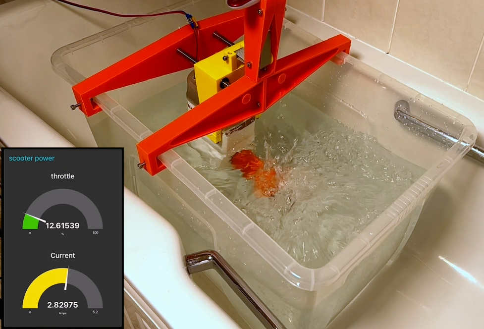
The only bit that I’ll mention here is that for testing purposes I though it might be a good idea to create a web app to monitor the status of the scooter during testing that I could access from my phone. I’ll talk though the specifics of the final design of this in the next video, as the current solution is really geared around getting realtime data out of the sea scooter for live, partially submerged testing. Rather than the final solution which will have different connectivity constraints.
![]()
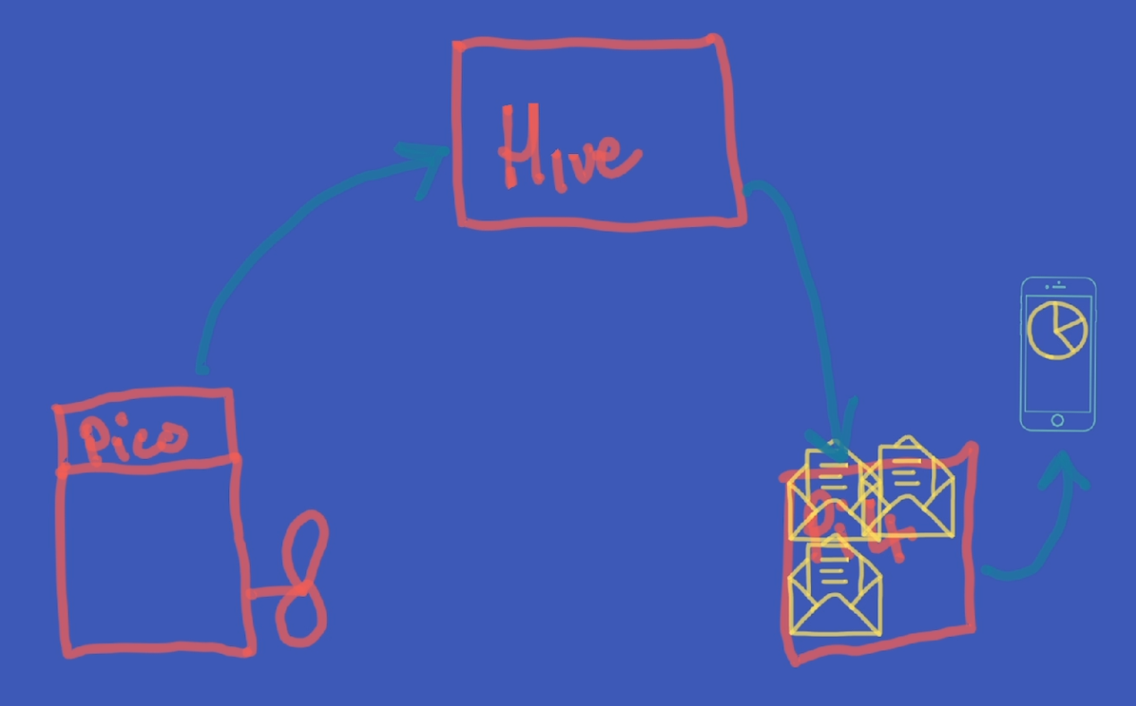
But in big handfuls the sendmqtt script on the Pico W, uploads, or publishes, every quarter of a second the complete state of all the sea scooter sensors as a set of messages with different tags, via WiFi, to something called a message broker, for this I’m using a free cloud based one called HiveMQ. These messages are then stored in different topic ques based on the tags that they arrive with. I then built a simple application using the open access Node Red platform, installed on a Raspberry PI 4, that subscribes to these topics, collects these messages from the message broker and displays this information on some real time dashboards that you can view via a web browser.
Because it’s a locally hosted website I can make it look like an app on my phone and connect directly to it to monitor the sensors in real time and plot the values over time.
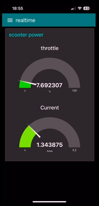
Here you can see the Realtime throttle value and current value from the web app on my phone.
![]()
![]()
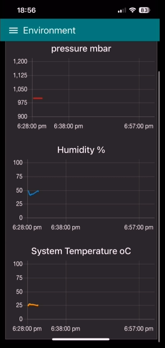
As well as the pressure temperature and humidity of the sea scooter over time.
Pretty neat eh.
In bath testing
Before i started ting I thought I might be worth iterating on the propeller design a bit and trying a few of the improvements that you popped down in the comments in the last video.
Firstly I took the three best designs from the last video and make sure that they are all the same scale as the original design intended them to be. I then flipped all the designs so that the they all have the same pitch direction so I don’t get caught out like I did last time. Next I printed them all using the smallest nozzle I have, which is 0.4 mm and the have a bit of a go at smoothing the surface and edges using sandpaper first…. Followed by a couple of coats of clear coat.
![]()
These small diameter props SHOULD be able to output more power with less torque required, which is good for the magnetic gear. Also the smaller diameter should ensure that the tips stay submerged during the testing.
![]()
Well that’s the theory anyway… check out the full video below to see how the electronics and props preform using the same test rig that we used last time. as it didn't quite go to plan.
But at least all the electronics seemed to be working as expected :-)!!
-
Designing a Non-contact drive system
02/28/2025 at 15:43 • 0 commentsIn this update I've been looking at the non-contact drive system for the propeller. where I have combined a non-contact drive system that incorporates reduction gear box, known as a magnetic gear, to better match the motor with the propeller.
If you are interested complete details of this part of the build process is documented in the below video
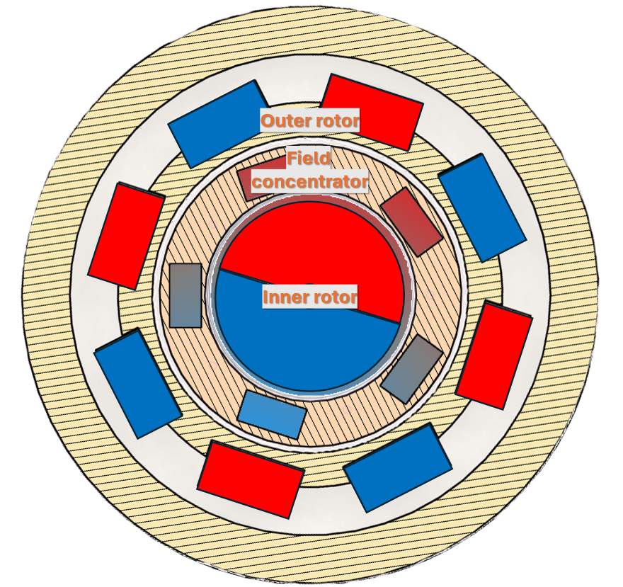
A magnetic gear is made up of three components a inner rotor, field concentrator and outer rotor. As the inner rotor rotates the outer magnetic rotor rotates in the opposite direction by an amount that is equal to the ratio of the outer to inner number of magnetic pole pairs. In this design the ratio is 4:1.
![]()
If you’re interested in more details of the construction of the magnetic gear, how it works and performs check out video below.
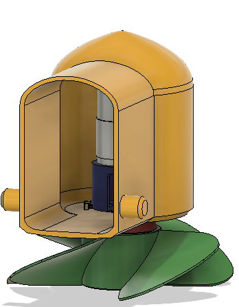
Incorporating the magnetic gear into the hull.
For this design to work I needed to be able to incorporate the field concentrator layer that contains 5 soft iron field concentrators into the wall of the hull that I need to be able to printed together with the hull in one go.
The simplest setup I could come up with to test this integrated magnetic gear design was to create an access port in the hull and add a motor and motor mount. Powering the motor remotely using an external power supply.
![]()
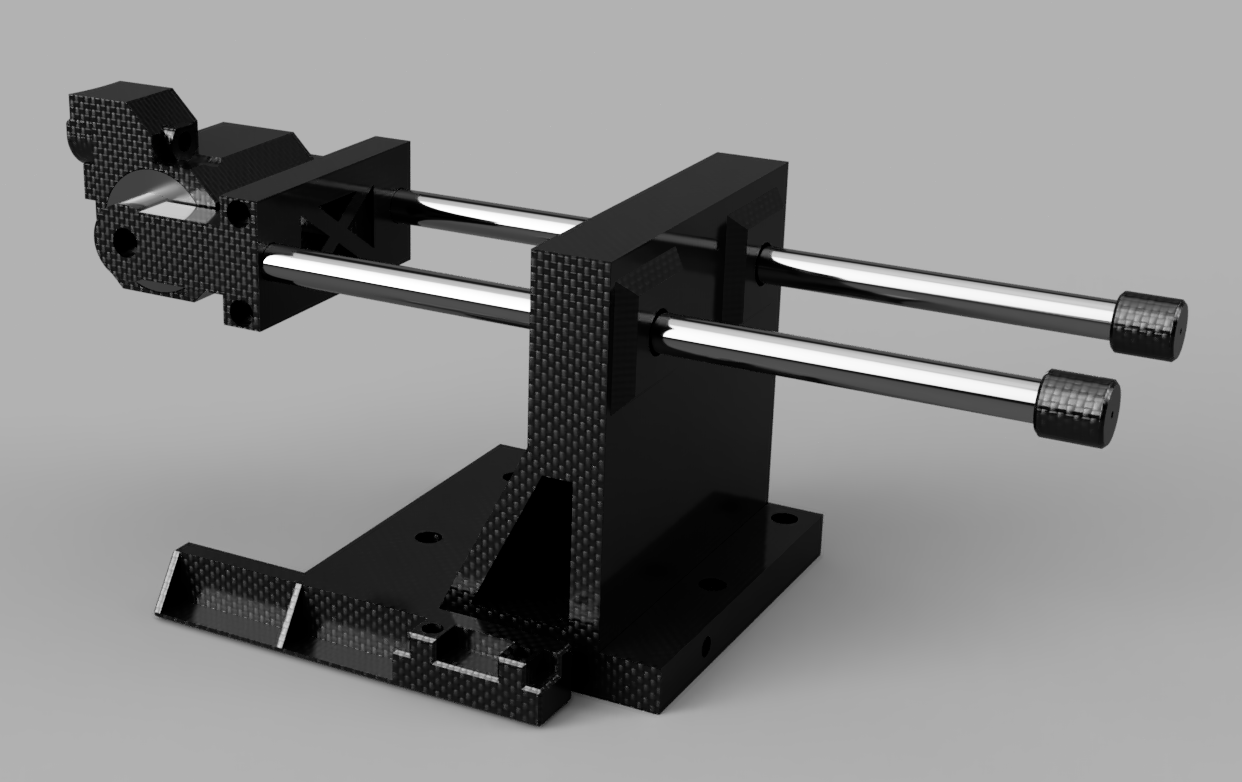
I also need to cut some 5mm thick strips of low carbon iron to use as the magnetic concentrators. To make this easy for myself I decided to build cross cutting jig for my DeWalt mini grinder.
![]()
This design also incorporates a fence to make cutting the same dimension easy. As you can see it does the job fairly well. The only slight addition worth incorporating in to add a bit of metal angle to the fence and square edge that are in contact with the part being cut to prevent the plastic from melting.
If you want to see how the cross cutting jig is designed and put together check out the video I made on it below.
I then glued the shroud on to the hull and then coated the surface in epoxy. This time I tried some readily available 5 minute epoxy that you can get from the local hardware store rather than flexible epoxy as I’m not expecting there to be much elastic deformation of the plastic this time around compared with the pressure testing video and it’s much, much quicker to cure.
only thing left to do was to cut out the plastic window and make some holes to pass though the power cable and attach it to the hull and we are good to start testing.
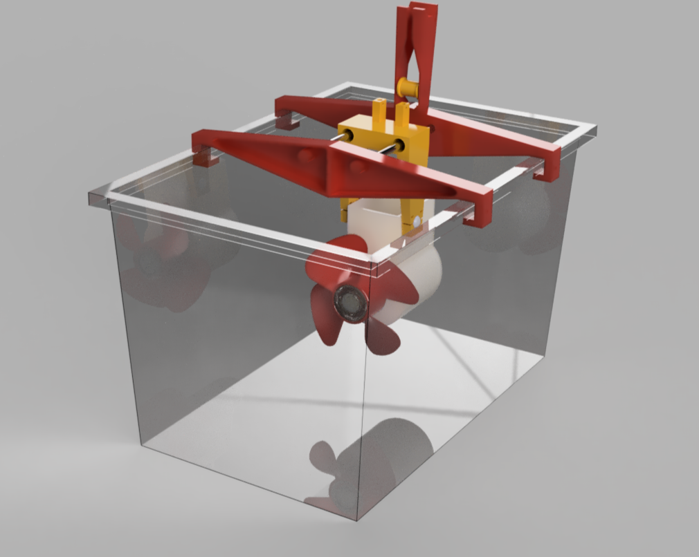
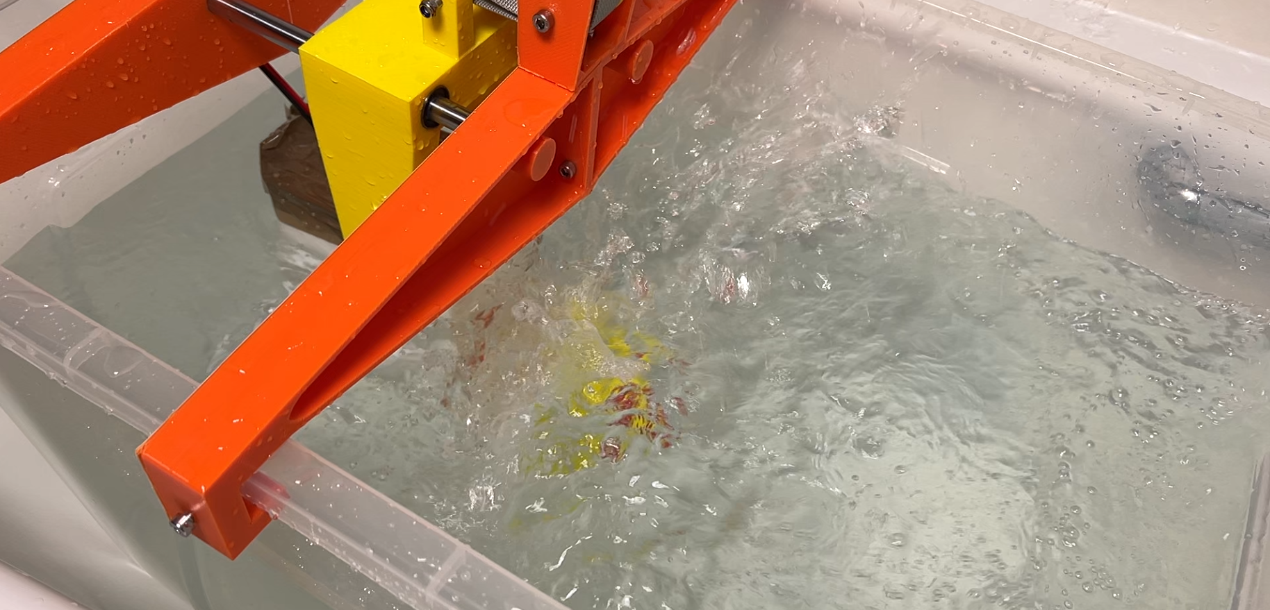
Testing rig design
I need some sort of test rig to measure how much thrust the test hull propeller combo actually produces. So I decided to take the biggest plastic box I could find add a gantry and sled to it and attach the test hull underneath it. That way I can constrain the motion to one dimension to measure static thrust. The only other piece I needed was to actually measure the thrust. I could buy a load cell, calibrate it, attach it to a micro controller and some sort of display. Or I could just repurpose a luggage scale that I have which has a resolution of 10 grams or 0.1 newtons which should do the job. Just needed to add a pully to ensure to transfer the force from horizontal to vertical so that I could read the display and keep it nice and dry.
![]()
Propellers to test
I decided to test 4 contrasting designs for propellers to see which is the best match. These designs where some of the top ranking prop designs for the rctestflight propeller competition that was run in the summer. Thanks to rctestflight and the participants for making the designs available. If you’re interested in the detailed test of how these and a whole bunch of other propellers performed then you should definitely take a look at rctestflight’s channel and the final competition video.
Lets print out the props.
![]()
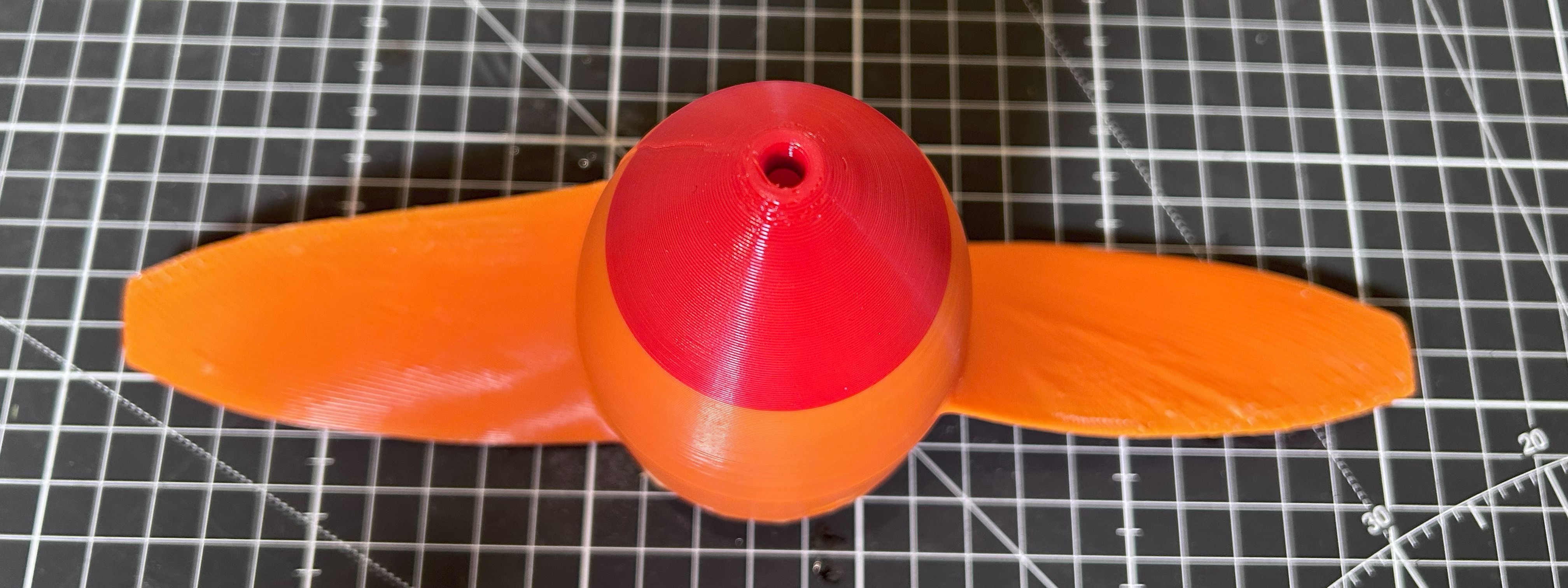
Design 1 - known as the spanmaxxing it’s a two blade prop with the end of the blades clipped with a steep angle of attack on the root. ![]()
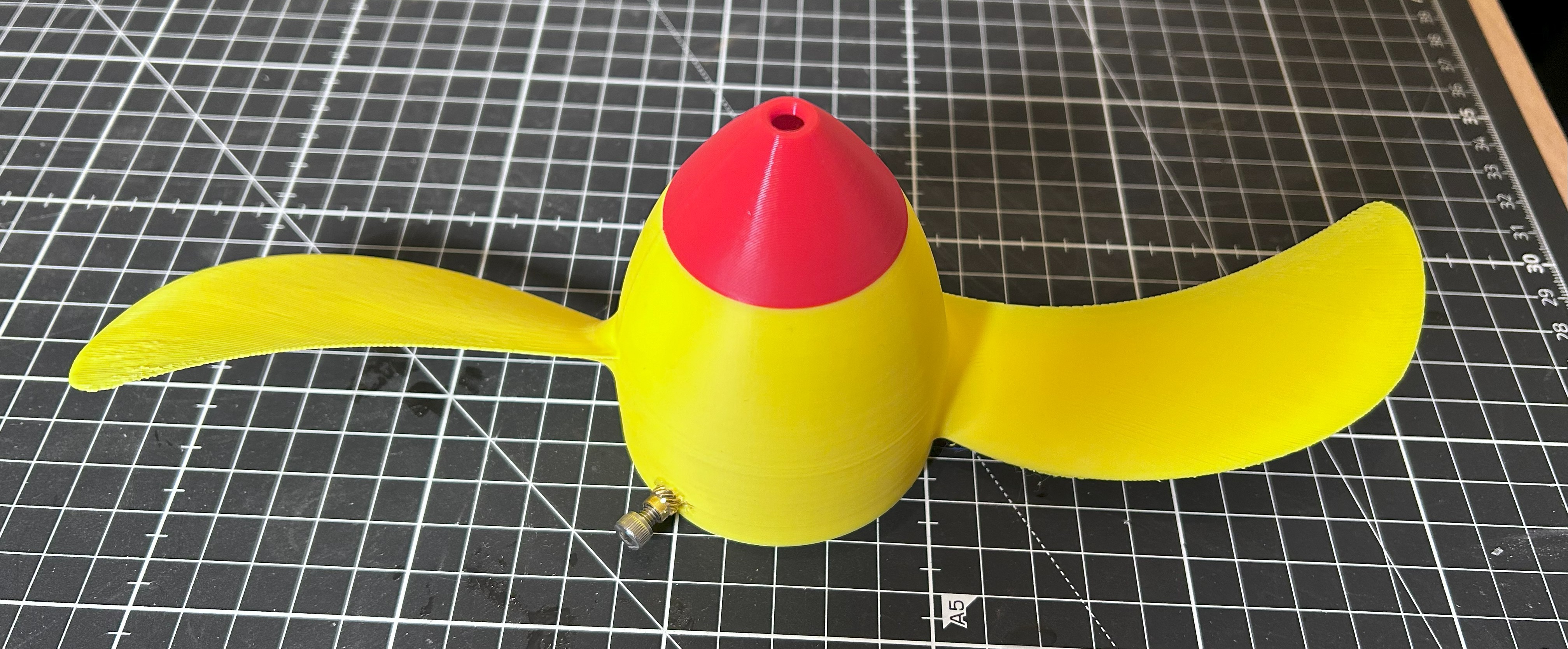
Design 2 – is a another 2 blade prop, with a really thin profile and a slight sweepback on the blade. ![]()
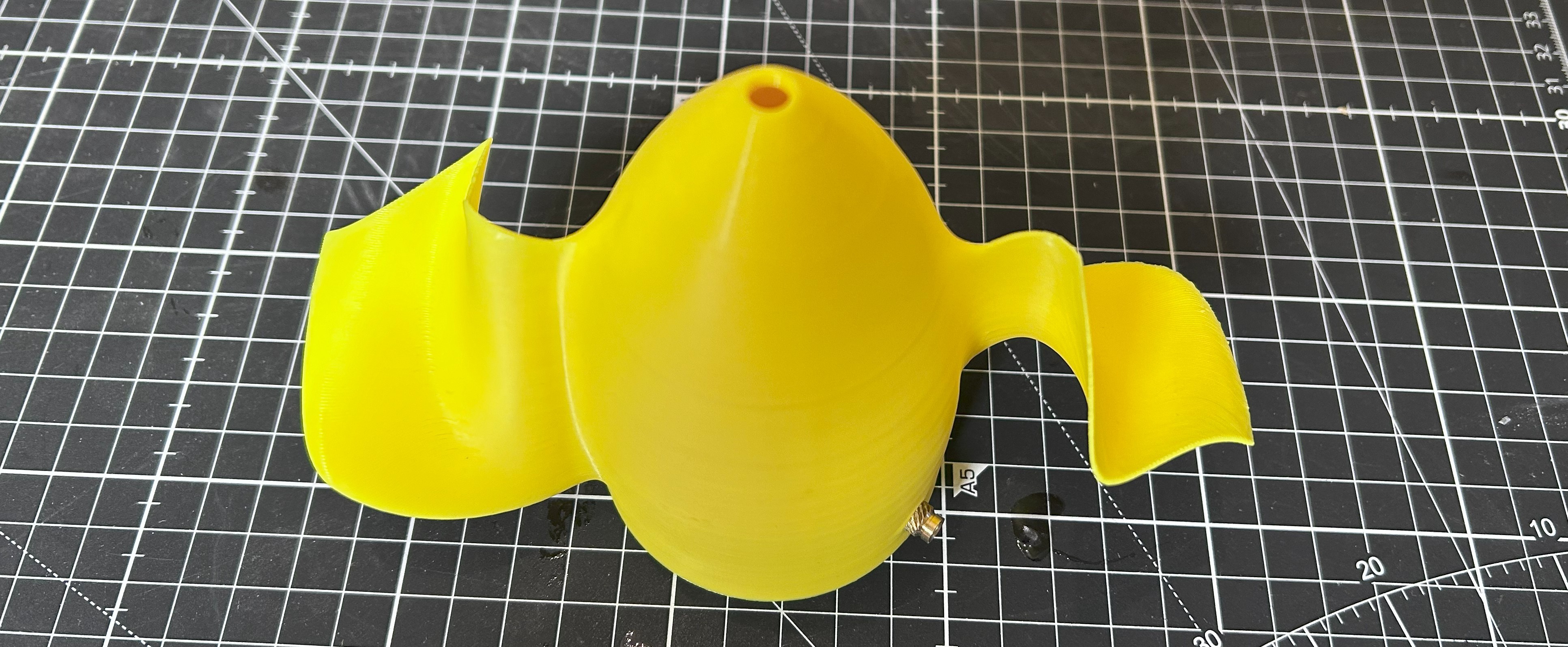
Design 3 – This is a 2 blade design with a really unusual concertina blade shape, with a much smaller overall diameter. ![]()
Design 4 – Is a toroidal shaped blade. Where there are no blade tips. This one has 4 blades and again a smaller diameter. I was particularly interested to see how this one does as toroidal blades are supposed to be much quieter. For reach test I set the power supply to 24 volts and ramp up the current in 0.1 Amp increments from around 1.5-2 A to around 4 Amps.
![]()
I've gone though the out come of all the testing in the video at the top of this log entry post!
For the sea scooter design I’m actually leaning towards the toroidal propeller as it seemed the most stable, was the quietest by a mile and had the second highest max power output. It was also printed with the 0.8mm nozzle so the printed surface was very rough, so plenty of room for improvement there. Definitely scope for a second round of testing with smaller props that have also been made smooth. I wouldn’t be surprised if we can eek at least another 10% of thrust.
-
Waterproofing the Hull
02/28/2025 at 11:30 • 0 commentsOk so the first challenge was to see if I can actually make a 3D print waterproof. if not this project is sunk in the water.
For this to work I'm not just talking about whether the print can hold water. But need something that can stand up to some serious water pressure without springing a leak....
if your interested in the phase of the build then be sure to check out the video below as it has all the details of the build so far.
I needed a pressure test rig for that.
Ok so to test whether the sea scooter can to handle this kind of pressure. i first had to design a pressure testing rig!
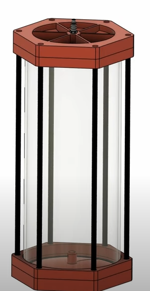
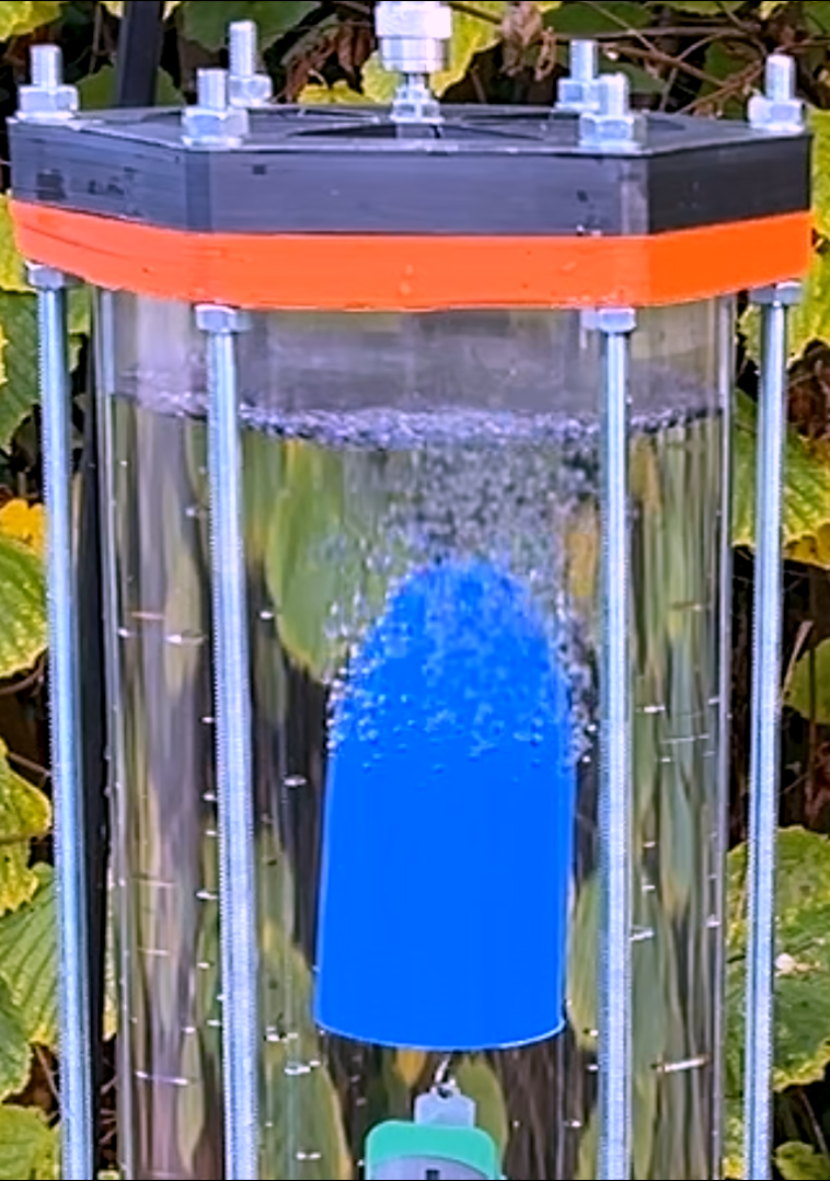
I went for a design that consists of a polycarbonate cylinder with 3D printed endcaps also out of polycarbonate. well actually polycarbonate carbon fiber in the end... These form a tight seal with the cylinder using a large silicone O-ring. With either end secured in place with 6 pieces of M10 threaded rod. It was then filled with water and a ¼ inch air hose fitting taped into the top so that I could connect it to an air compressor to pressurize the test rig.
![]()
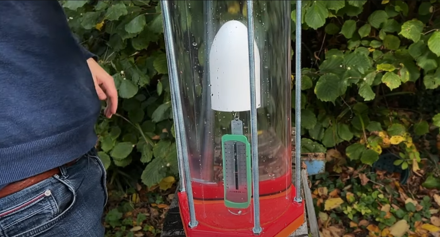
The samples where attached to this load spring and submerged in the tank to measure how buoyant they where, and how this changes over time. The idea being that either water iwould ingress and compress the air in the cavity – reducing the buoyancy, or water would ingress and air would leave as a stream of bubbles – reducing the buoyancy. As a back up I also weighted the samples before and after to measure if they took on water.
![]()
I tested a scaled down, simplified version of a sea scooter hull to make the testing as representative as possible. (white object above)
If you do a quick search you’d find quite a bit of material on ways to water proof a 3d print. It’s not all entirely consistent. but after a bit of thought I think I found a good set of parameters to test. (details in the above video).
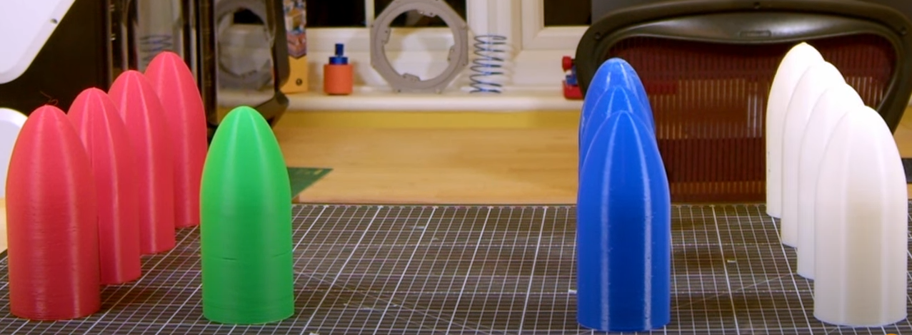
I tried ASA as the main contender and PLA as a reference. Trying these at a few different pressures up to a few Atmospheres (Atm) water pressure and also few post processing techniques like acetone smoothing and epoxy coating. So I needed quite a few test hulls......!
![]()
There where some surprising results.
![]()
But post processing was definitely the way to go. The Epoxy coating in particular was able to stand up to more pressure than you might expect.
Print-in-Place Sea Scooter
Building a wireless print-in-place 3d printed sea scooter without the need for any holes or seals for connectors, power or even drive shaft!