 Nasser
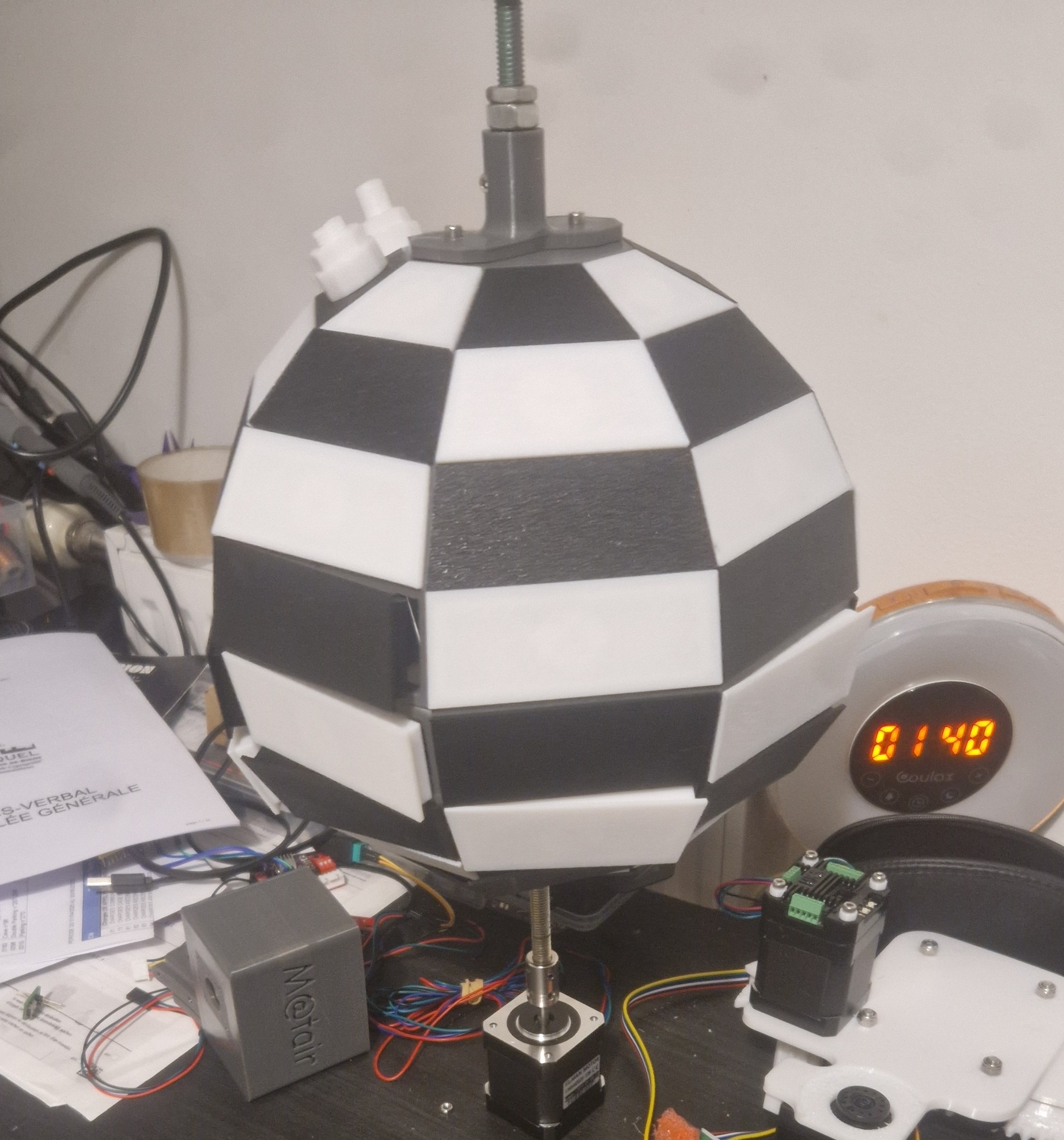
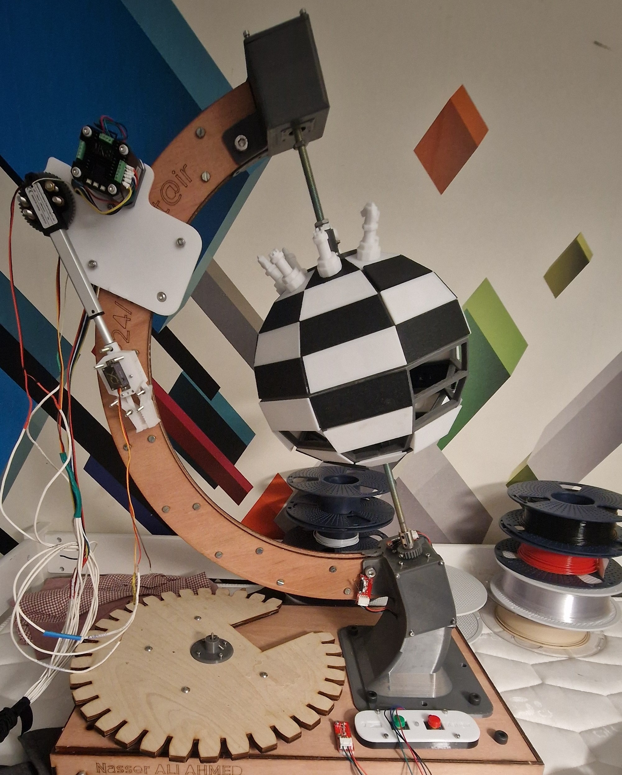
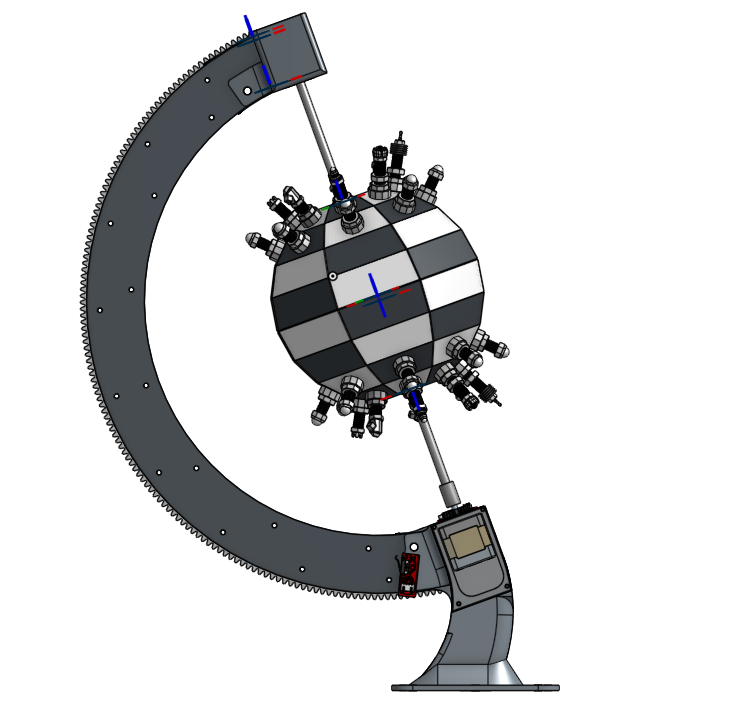
The goal of this project is to create a spherical chessboard where moves are played by a small robotic arm moving along a circular track.
The robotic arm will execute the moves made by players in an online chess game.
A spherical chessboard where a robotic arm plays moves from an online game.
Already have an account? Log in.
To make the experience fit your profile, pick a username and tell us what interests you.
The goal of this project is to create a spherical chessboard where moves are played by a small robotic arm moving along a circular track.
The robotic arm will execute the moves made by players in an online chess game.
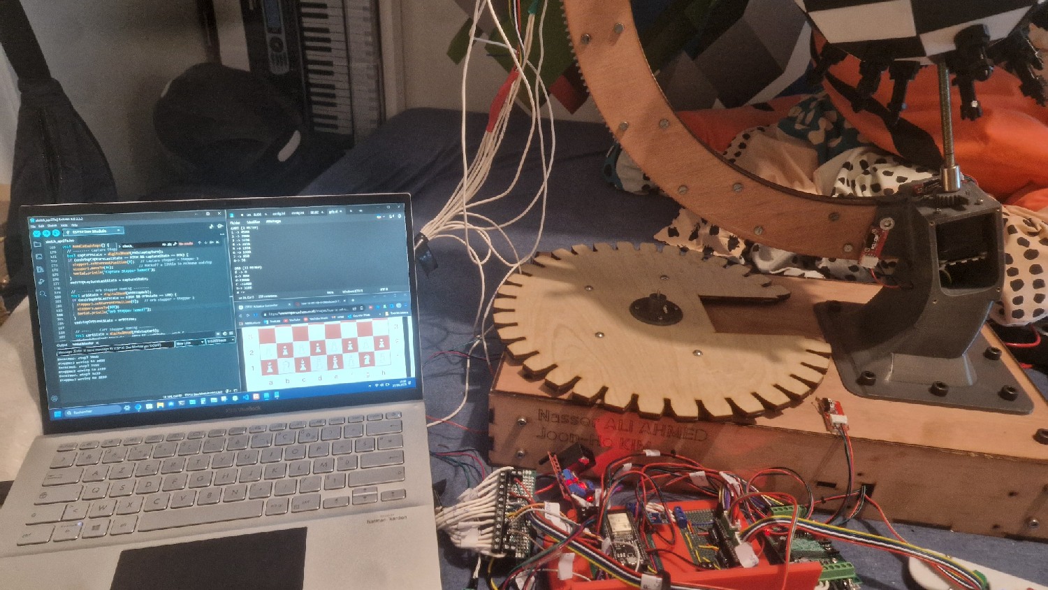
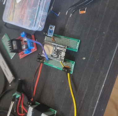
Once the project was working, we ran into many electrical issues and signal noise, especially with the servos. Our original wiring was a mess, which made troubleshooting a nightmare.
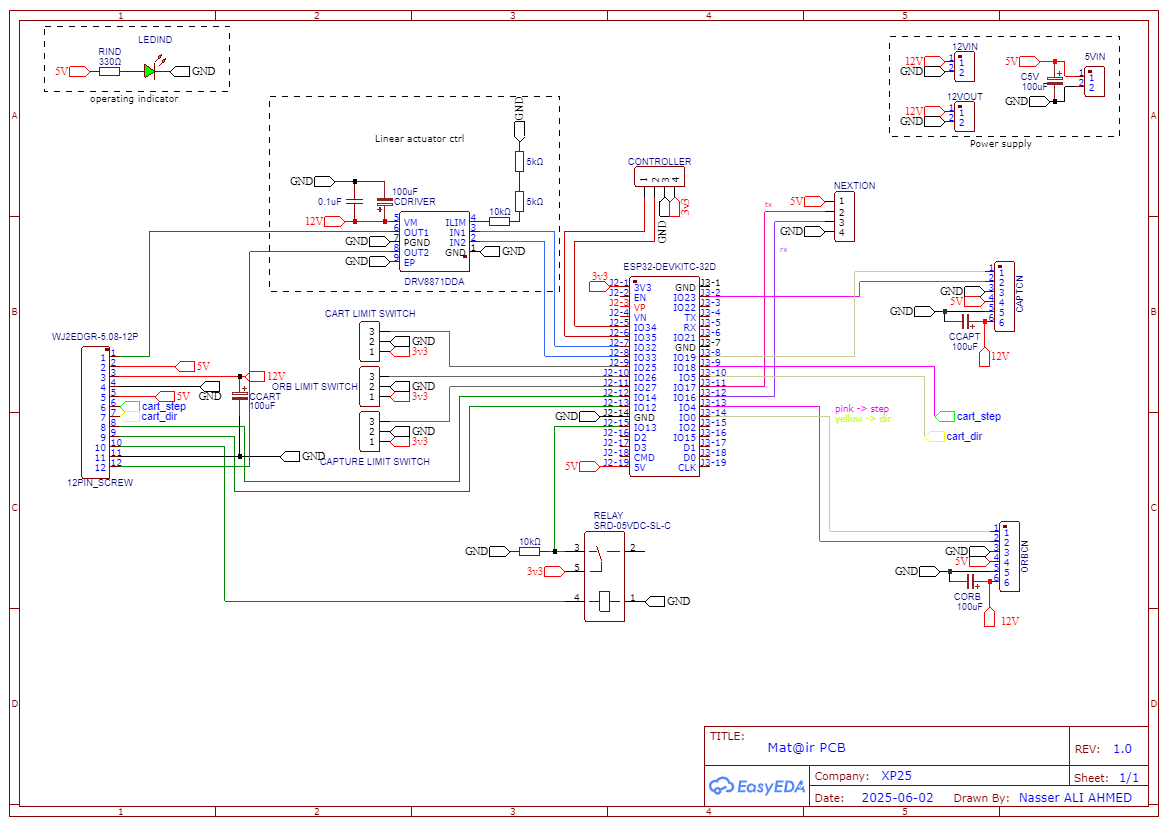
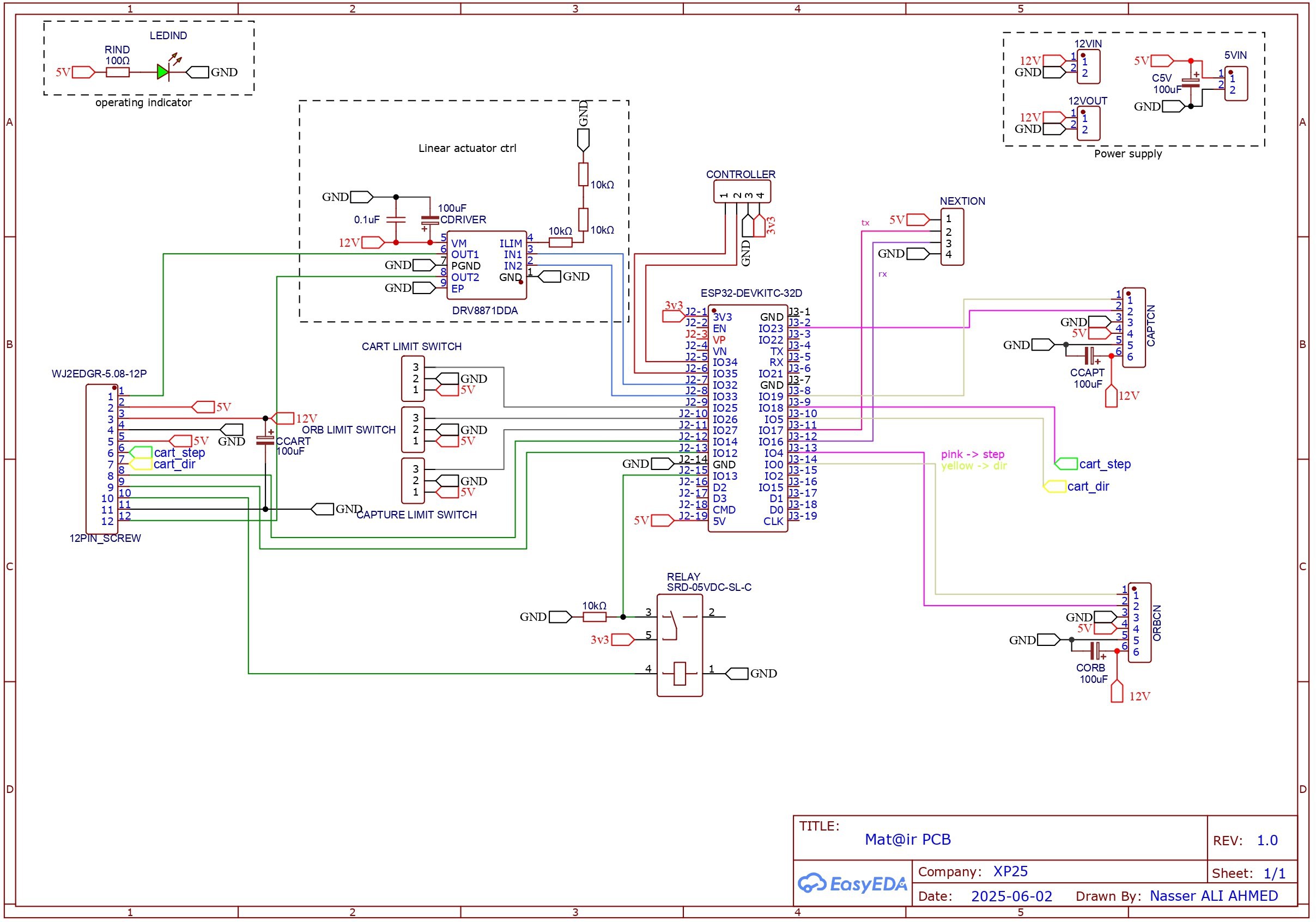
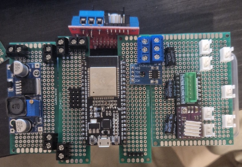
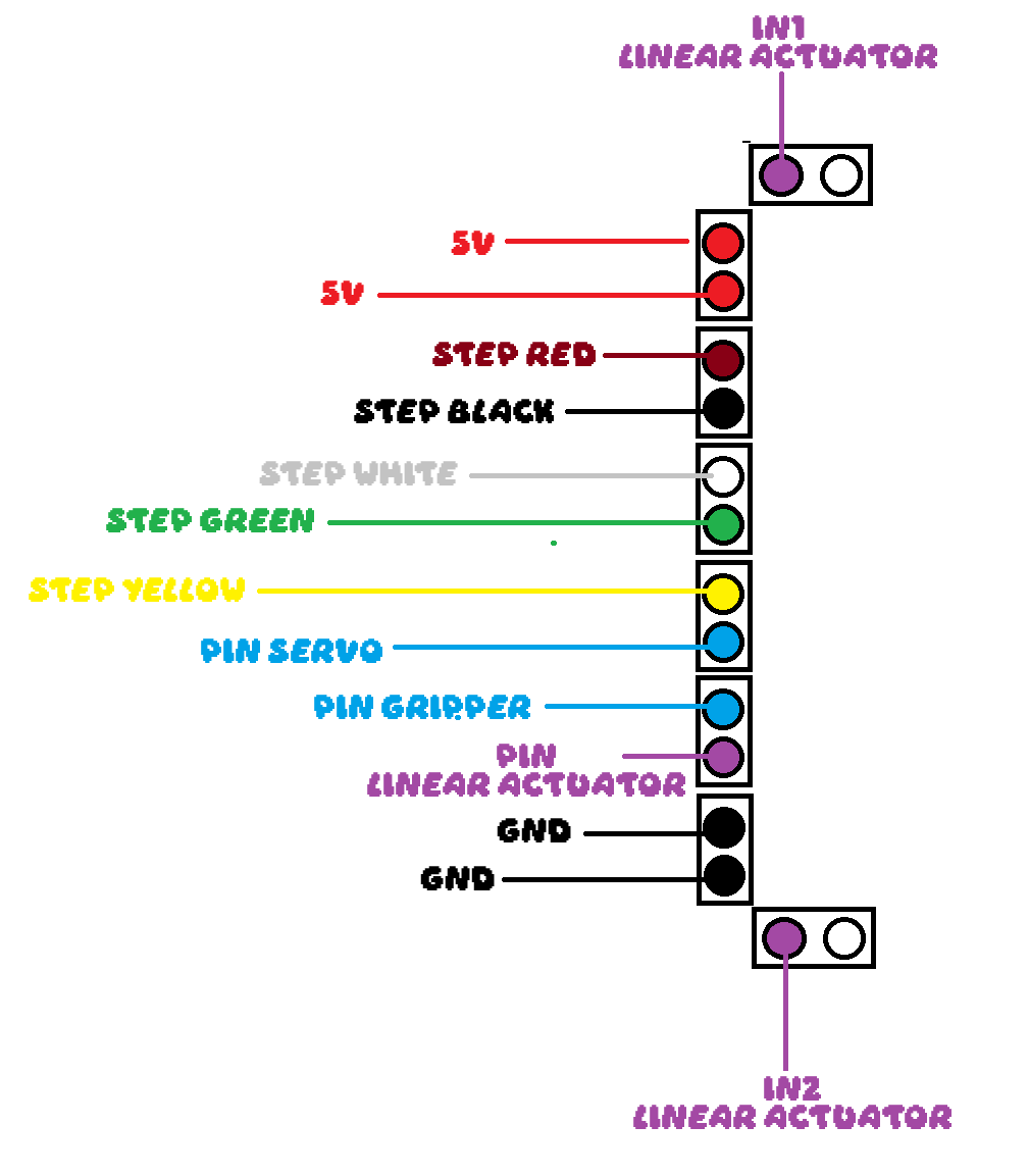
We upgraded to a PCB to solve this. Here is the wiring diagram:
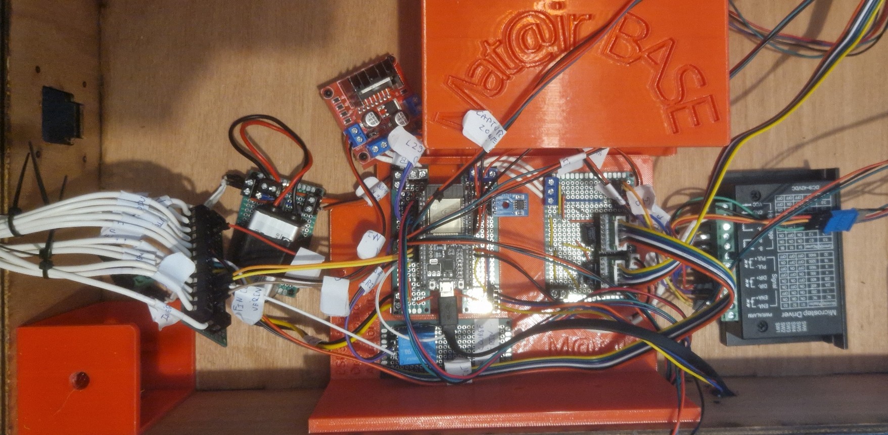
The PCB:
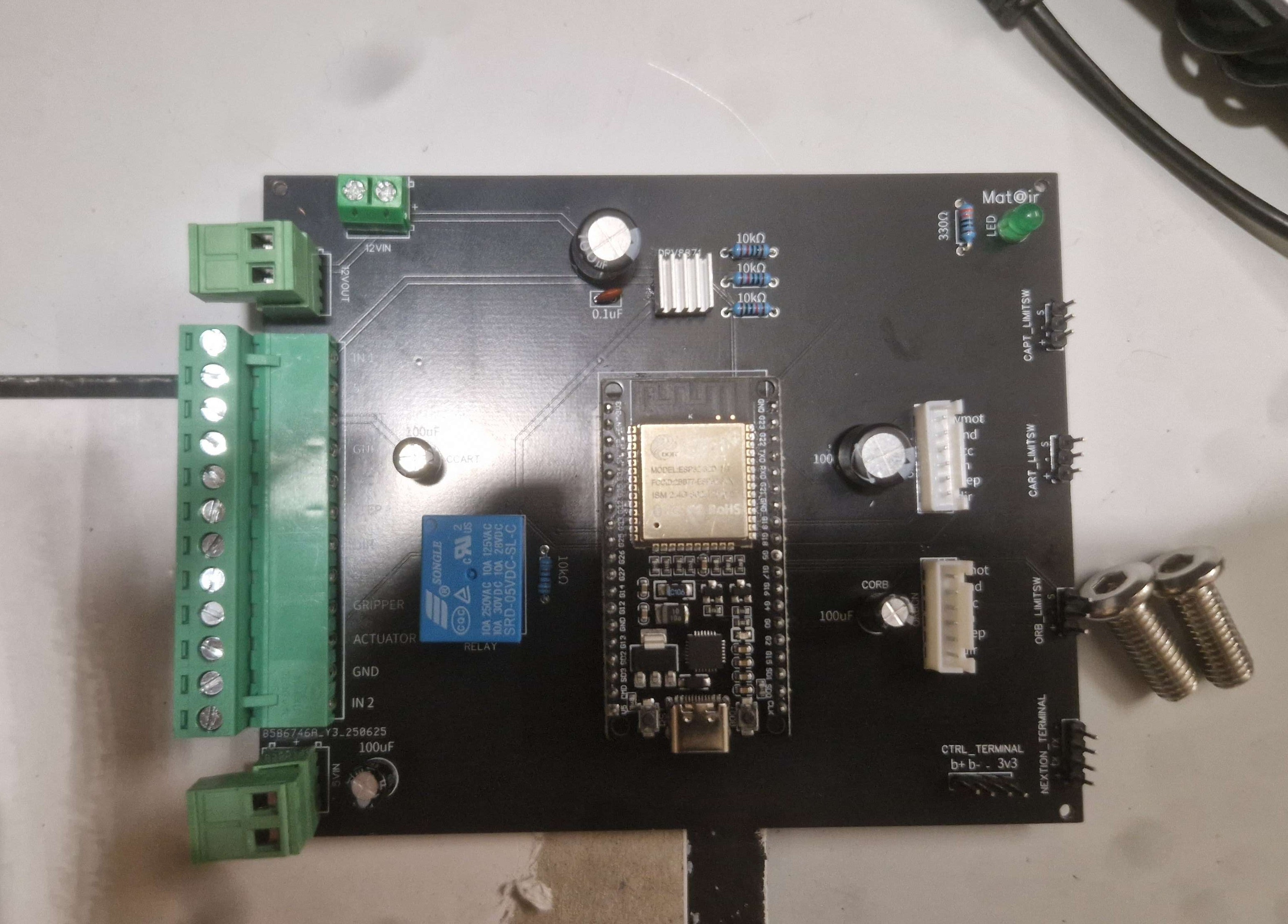 |
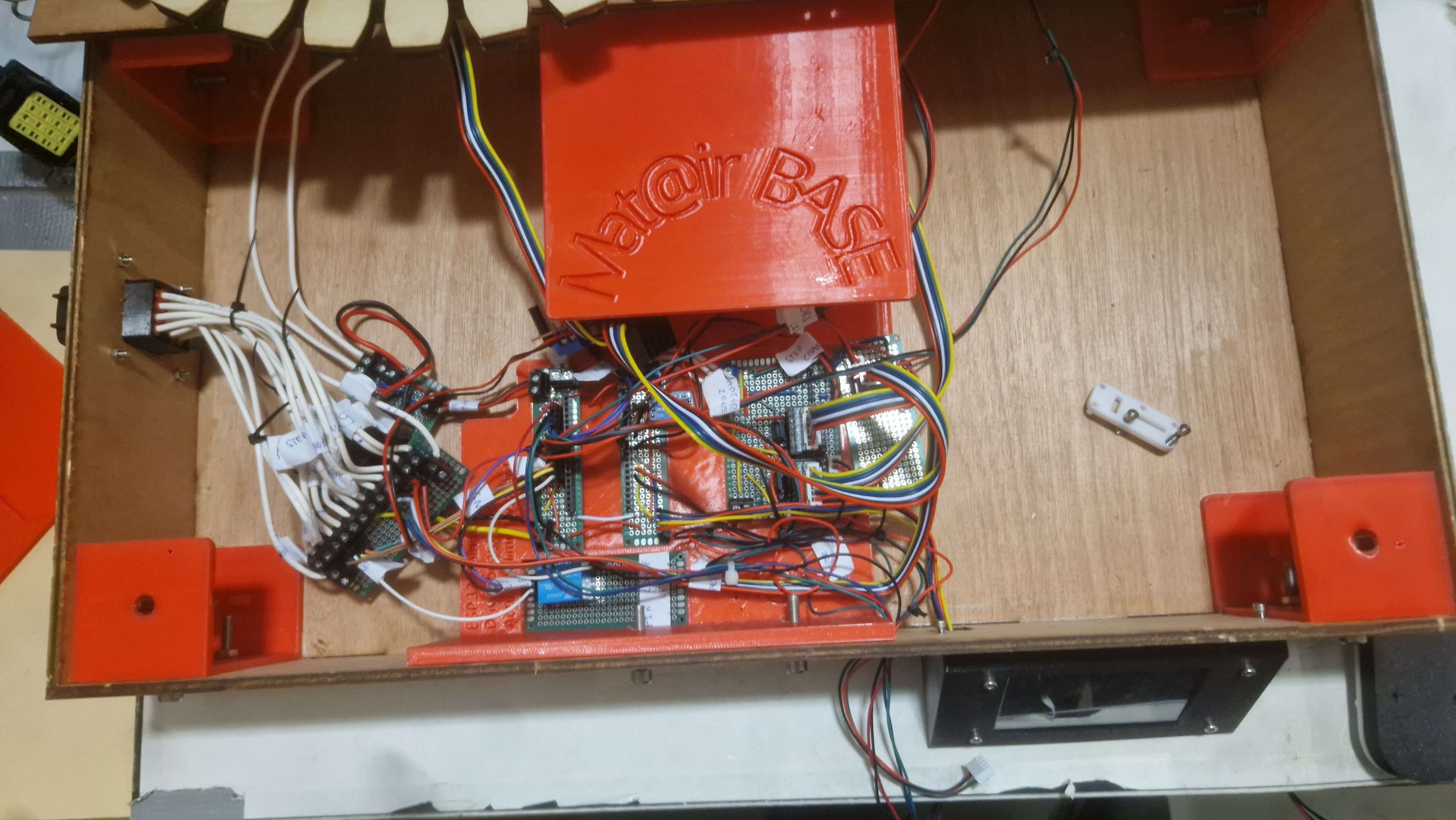
This is how the wiring looks now.
With this latest addition, we have decided to end the project.
With the mechanical and electronic parts assembled, we moved on to programming to connect the motors, servos, sensors, and user inputs.
We defined the main behaviors the system needed:
We wrote the program for an ESP32 using the Arduino framework. Since networking code ran in the background, all motion routines had to be completely non-blocking.
We used multiple state machines to control the cart, gripper, capture system, board rotation, manual controller, and screen.
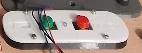
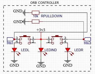
We started with a simple test program for the controller. Using the two buttons, we sent signals to the actuators to confirm the mechanical and electrical systems worked
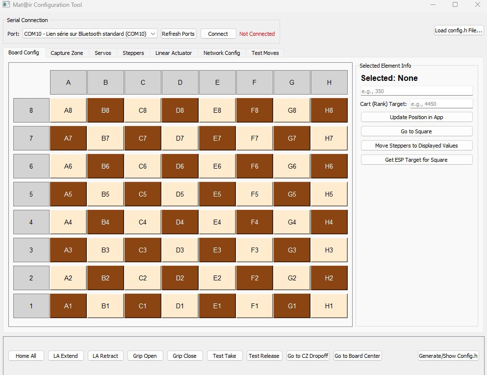
After that, we wrote a second program to control the actuators via serial commands from a computer. We used this to figure out the right angles and positions for each motor to reach every square on the board and the capture slots.
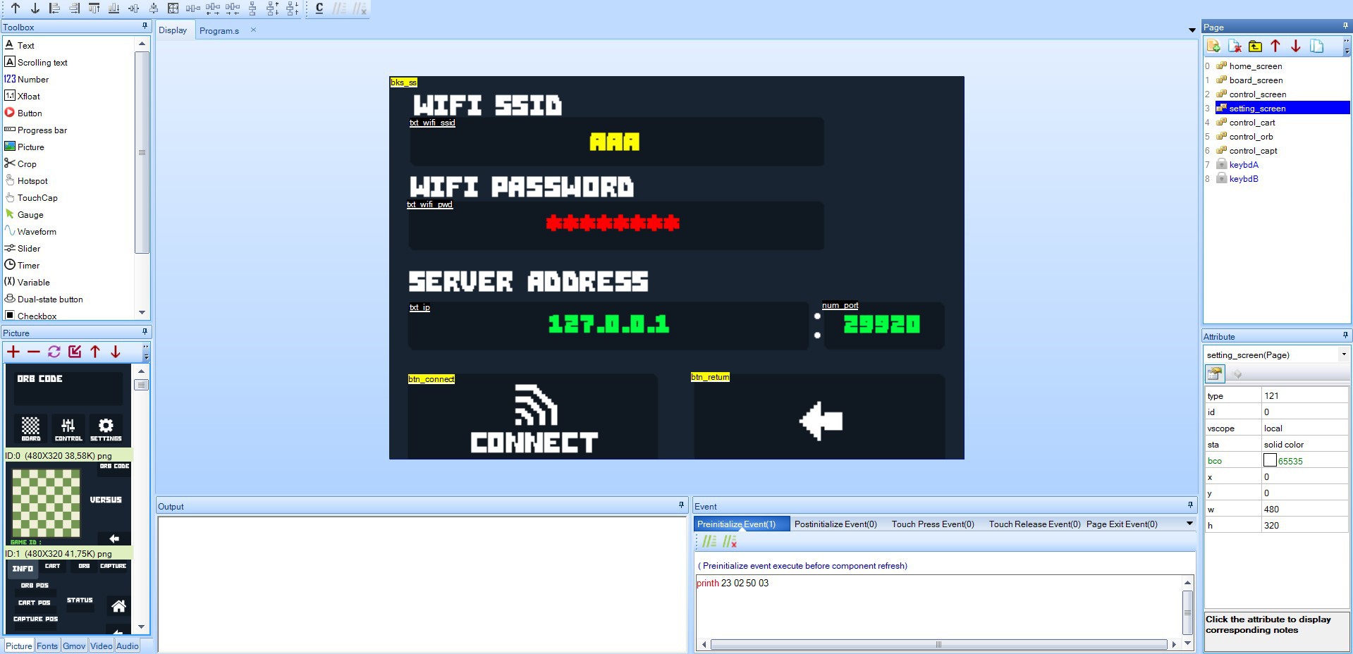
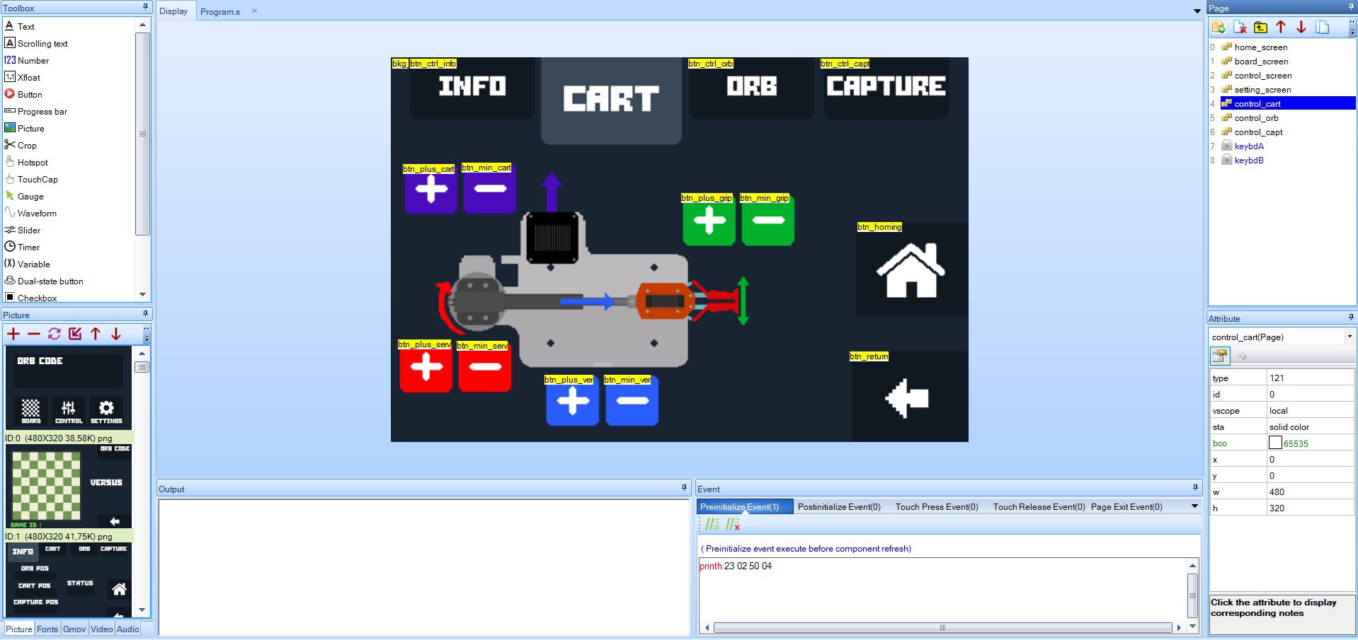
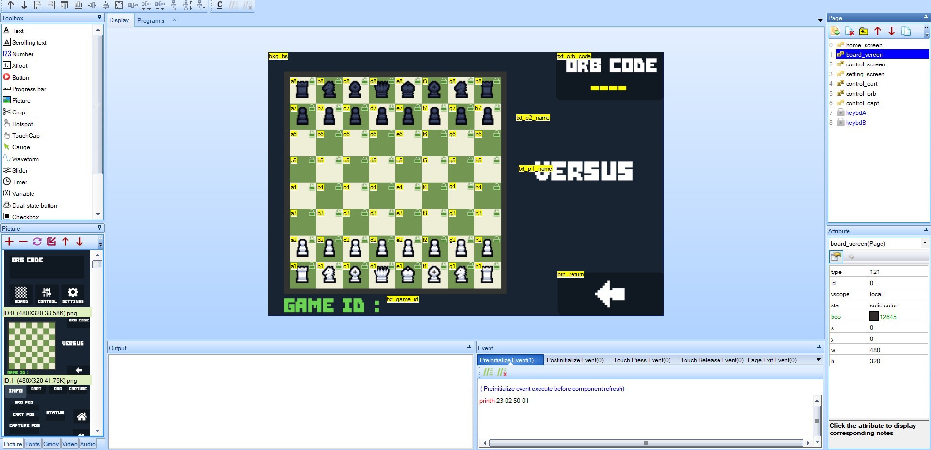
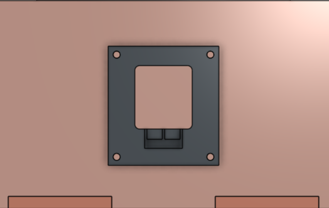
We used the Nextion Editor to build the touchscreen interface. It allowed us to:
Here are some screenshots:
The final motion control codebase was over 2000 lines long. It included:
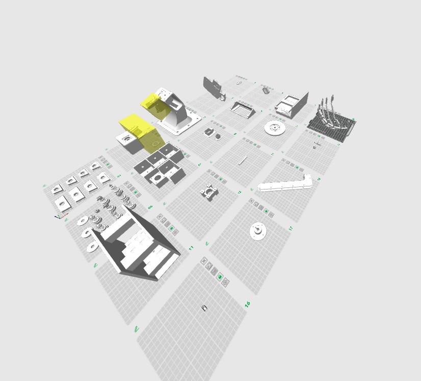
After assembling the mechanical parts, we moved on to the electronics. We laid out the components:
Next, we made the circuit diagram.
 |  |
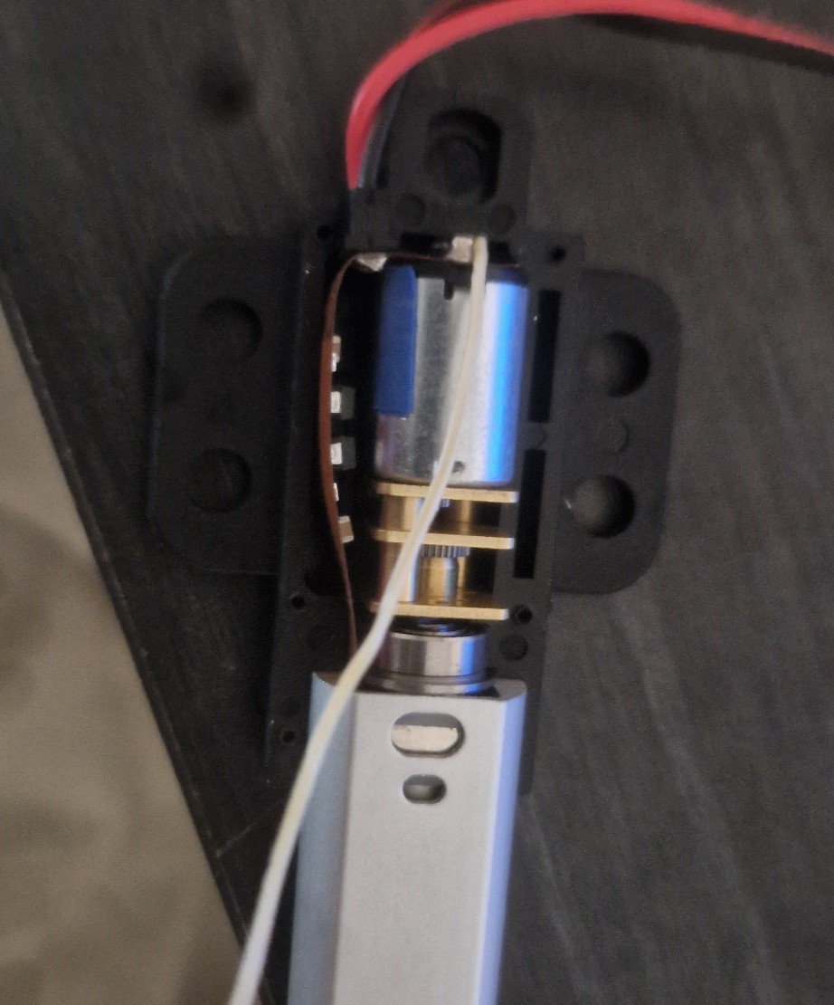
The diagram shows a relay connected to the actuator. We used this to detect when the linear actuator fully retracts. Because the actuator has an internal limit switch, we soldered wires directly to its motor terminals. This lets us monitor the motor voltage; when the current drops, the relay triggers, signaling that the actuator hit its internal stop.
We laid out the components on perf boards to plan the layout, then soldered everything.
Another major task was creating the cable bundle that connects the main circuit to the moving cart on the rail. To do this, we positioned the cart at its furthest point and measured out the cable lengths accordingly to ensure proper reach.
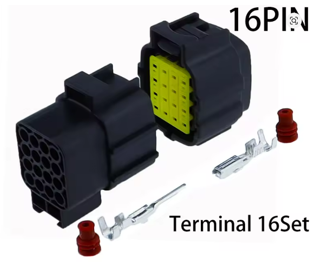
To allow for easy disassembly, we didn't solder the cart's cables directly to the circuit. Instead, we used a 16-pin connector like this:
We wired the cart to the male connector and the circuit to the female connector. Here is the final cable assembly:
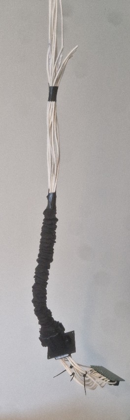 |  |
Finally, we installed the electronics into the base.
With the wooden and 3D-printed parts ready, we started assembly.
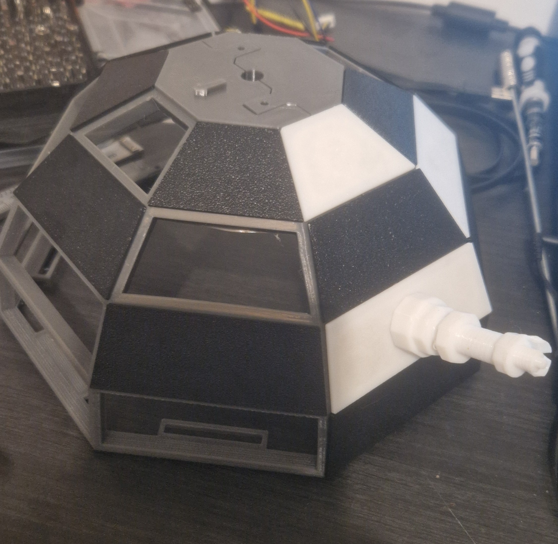
First, we built the spherical chessboard. We glued the four 3D-printed dome parts together using the built-in hinges and some epoxy. We inserted each square into its slot and added magnets so the chess pieces would stick.
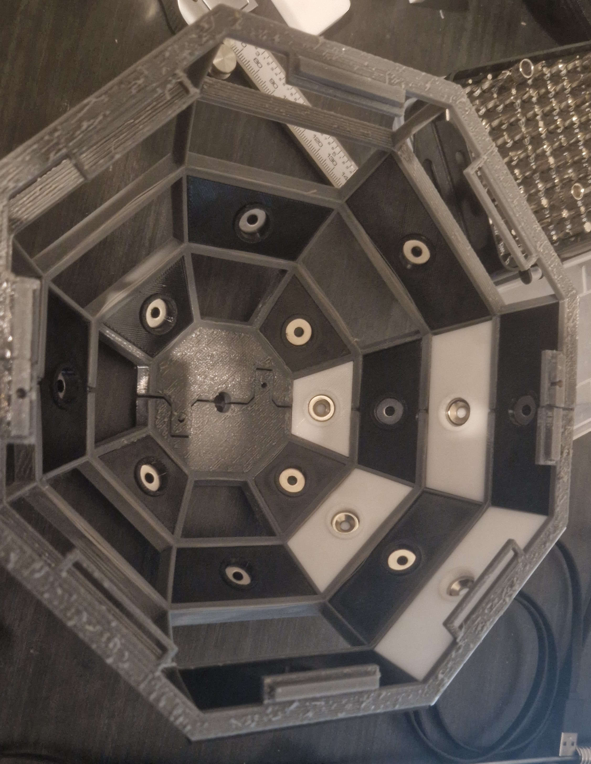 |  |
 |  |
Next, we put the cart together by installing the stepper motor, linear actuator, servos, and gripper into the 3D-printed body.
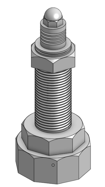
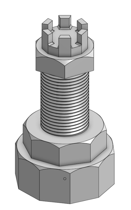
Then, we built the curved rail out of the laser-cut plywood layers, fastening them with M5 screws. We bolted the 3D-printed top and bottom supports in place using M8 bolts
Finally, we mounted the cart onto the rail and attached the bottom support to the wooden base.
This finished the mechanical build. Next up: wiring, programming, and testing.
After cutting the wood, we moved on to 3D printing. We printed:
We used PETG for the structural parts and TPU for the gripper. Everything was printed on a Bambu Lab A1 Mini (180x180mm bed).
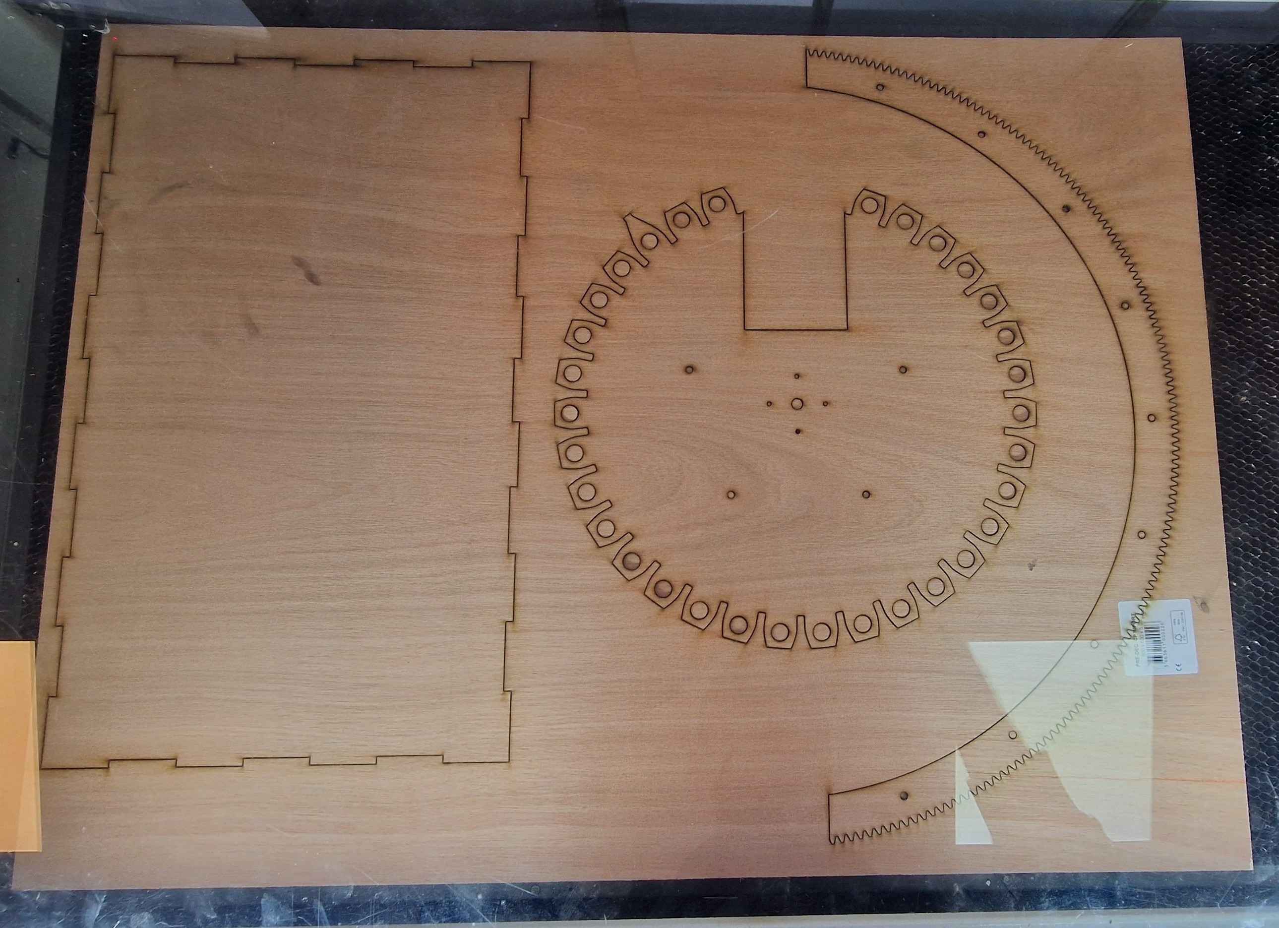
With the CAD done, we moved on to manufacturing. We started by laser cutting the wooden components. The design was built around 5 mm plywood for almost everything. We used:
Here is the cutting layout:
5mm plywood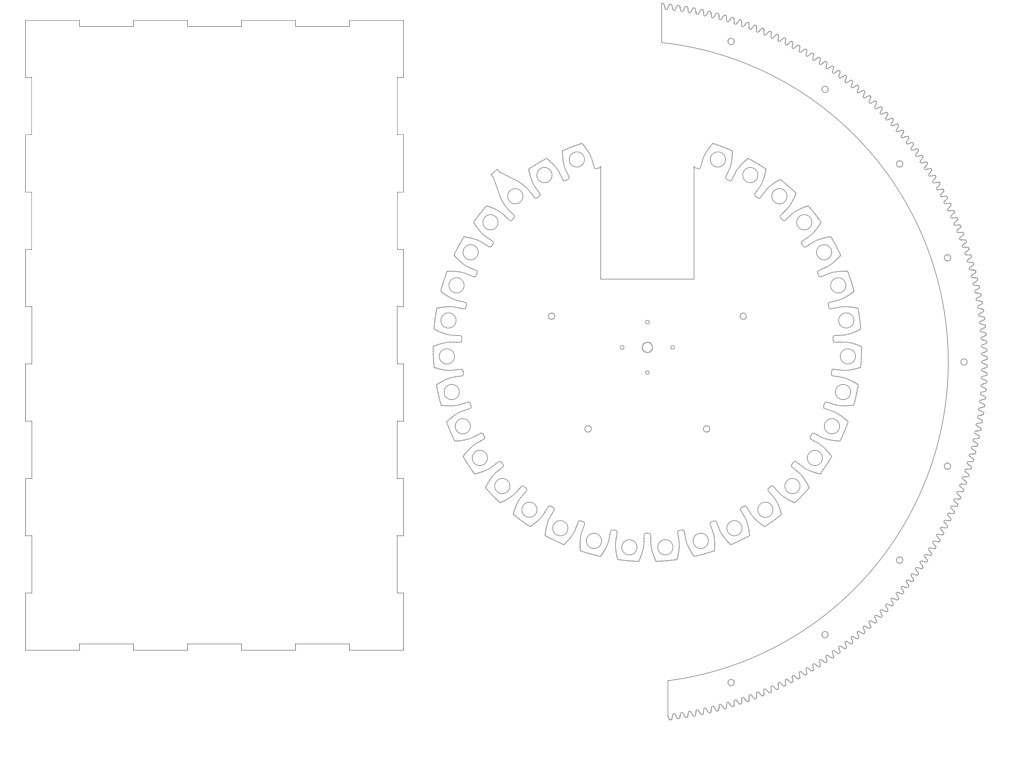 | 5mm plywood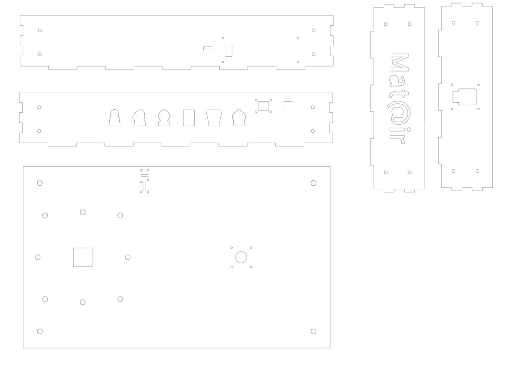 |
3mm plywood | 5mm plywood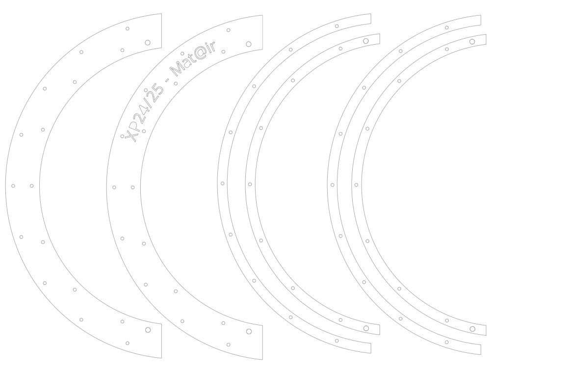 |
And here is the cutting process:
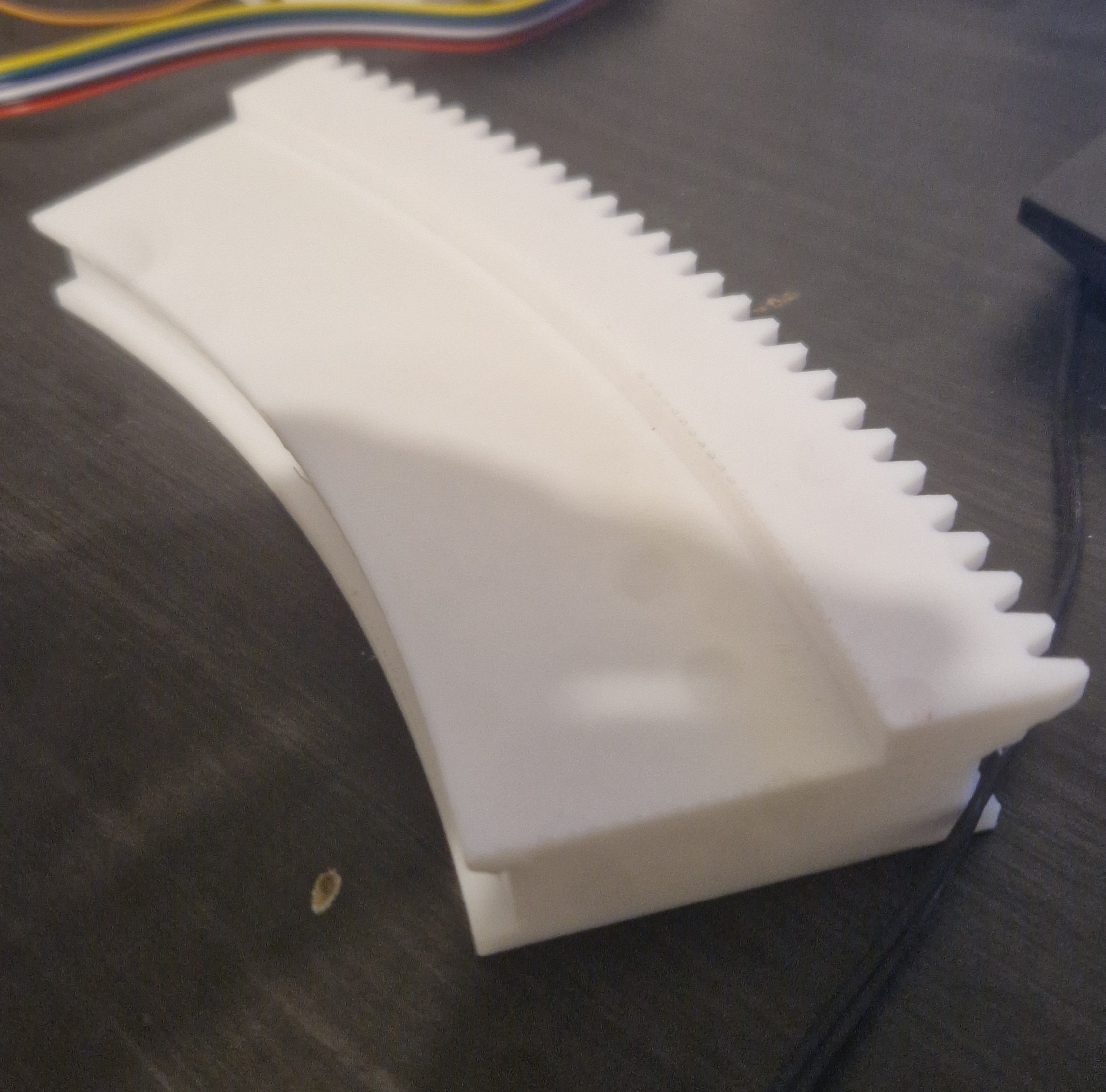
We did run into an issue later with the curved rail plywood gear: the teeth kept snapping off. To fix it, we swapped to 6 mm acrylic instead.
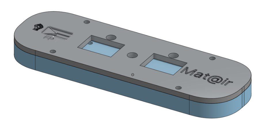
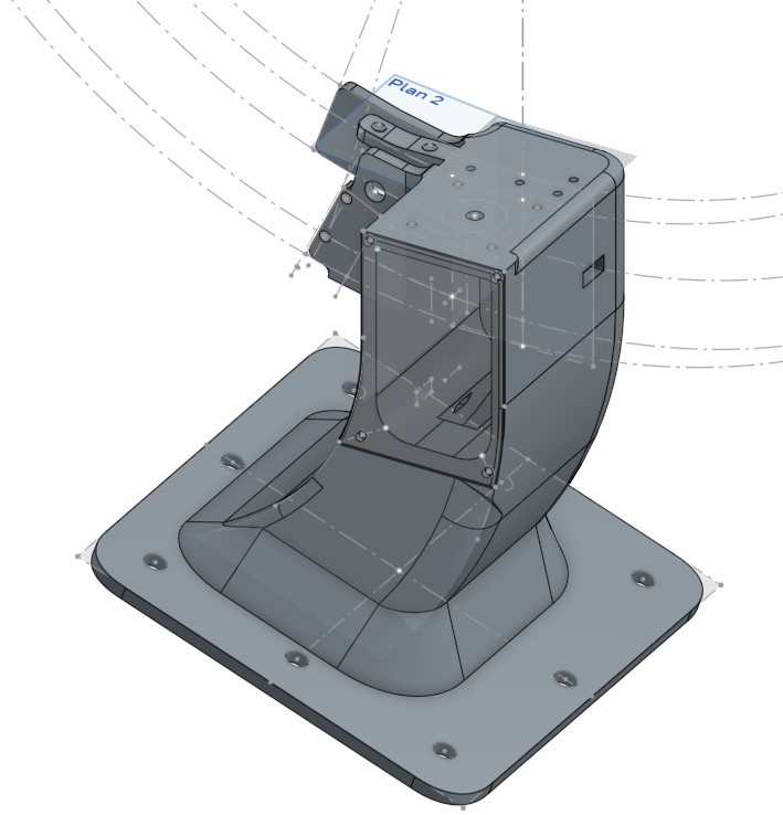
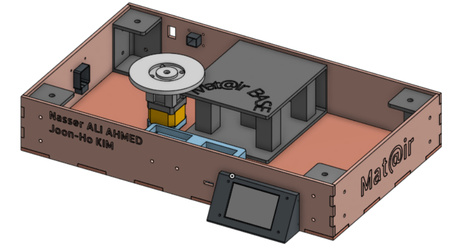
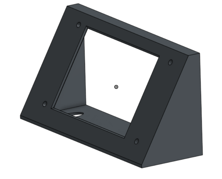
The last part to design was the base. It acts as a stand for the system and houses the electronics.
Our goals for the base were to:
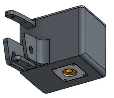
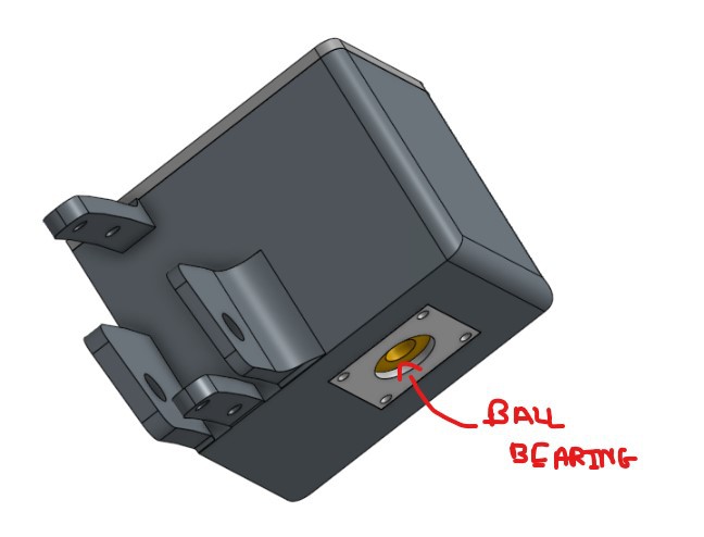
The core is a custom box for the internal components. It has cutouts for the cart cables and the Nextion display. It also includes mounts for the main board, supports at all four corners, and a central pillar to hold the wooden plate, globe, and rail
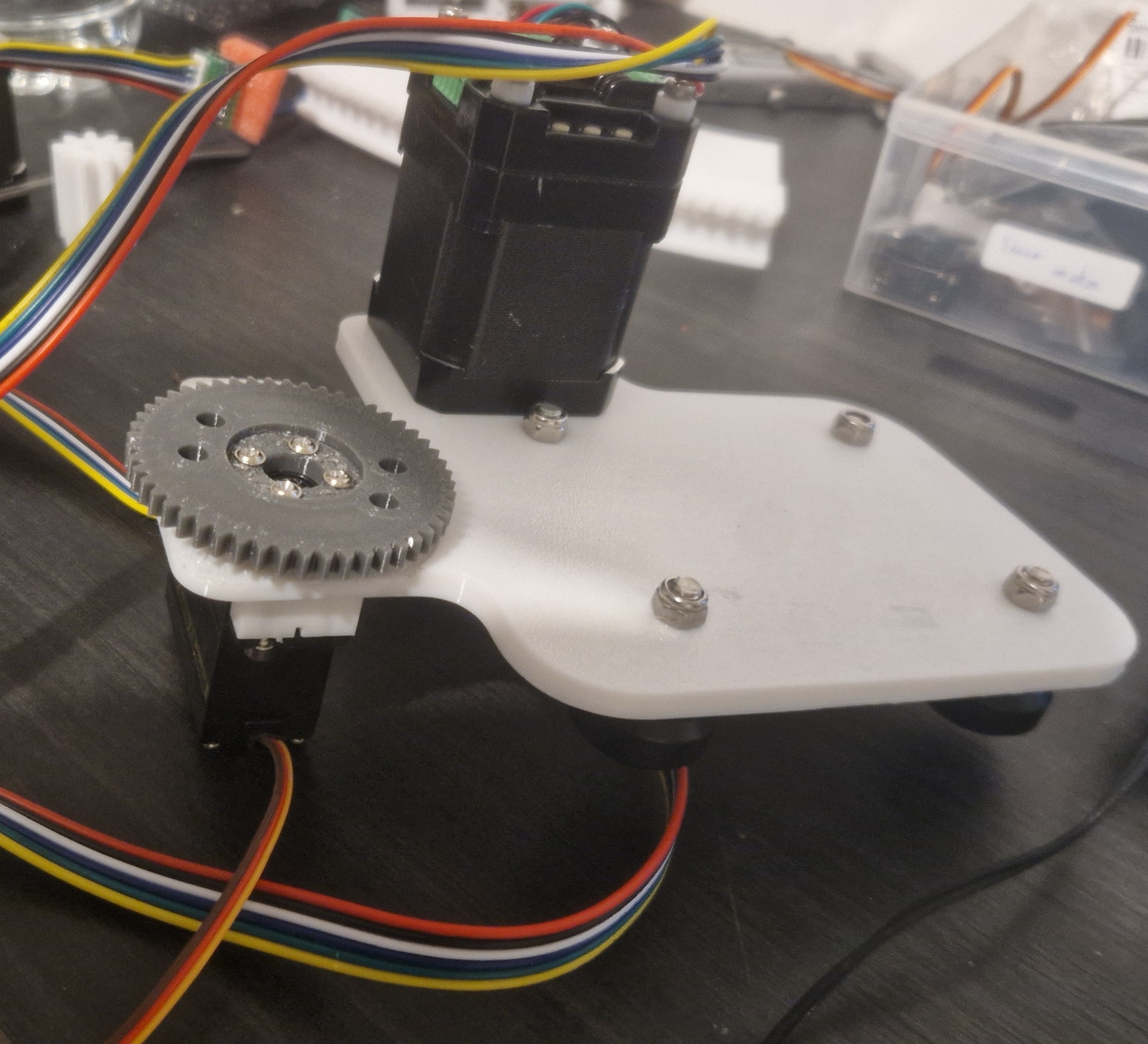
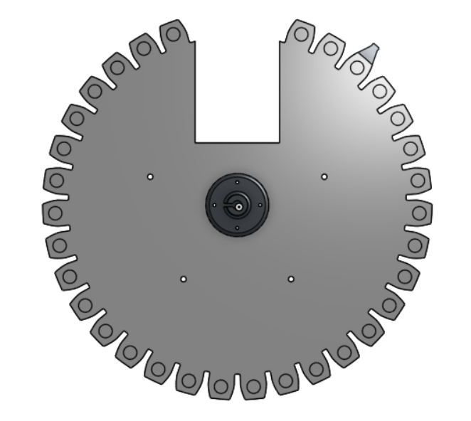
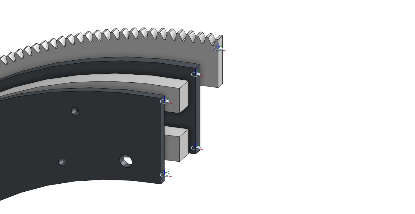
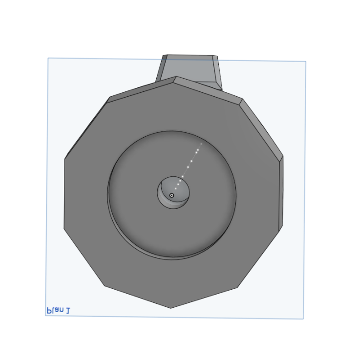
To store captured pieces, we designed a large gear-like structure with individual slots. A stepper motor directly drives it, rotating the gear to present an empty slot whenever a piece is captured.
Cart Connector: We added a cutout for a 16-pin connector (we only use 14 pins) that handles all power and signals to the moving cart. This makes the cart easy to disconnect for transport or maintenance.
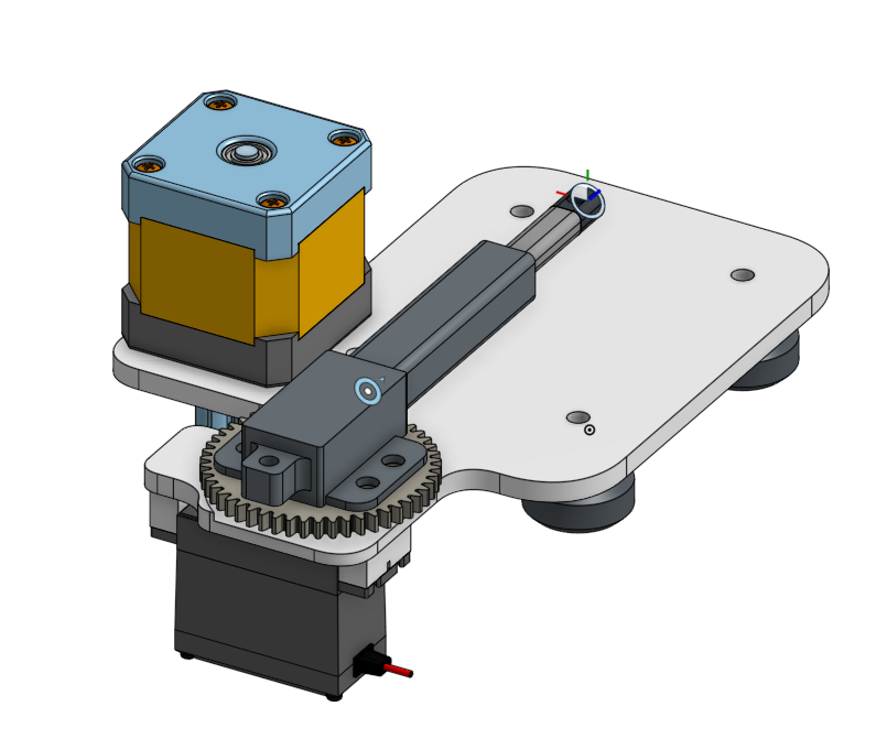
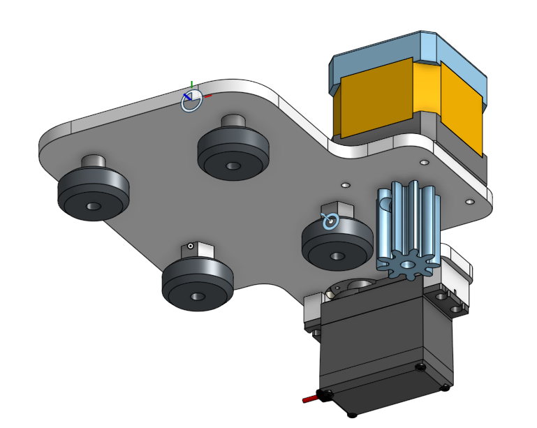
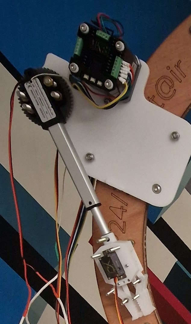
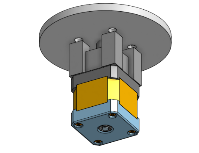
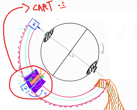
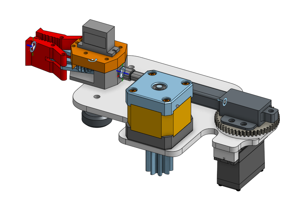
An essential sub-assembly of the entire system is the cart.
It needs to house four actuators, remain compact and precise, while smoothly moving along the curved rail and constantly counteracting gravity.
Components of the Cart:
1 stepper motor — to drive the cart along the rail
1 linear actuator — to extend and retract the gripper
1 servo motor — to rotate the linear actuator
1 servo motor — to open and close the gripper
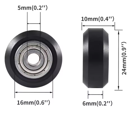
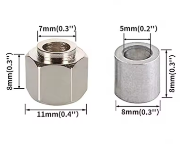
We use those cheap ender 3 wheels with 8mm column for our cart, the rest is 3d printed.
 |  |
For the design of the cart body, we drew inspiration from these two videos:
This was our initial iteration:
 |  |
To validate this, we also 3D printed a small section of the rail:
The tests confirmed that the cart could indeed move properly along the track
Building on our first test, we developed a second version:
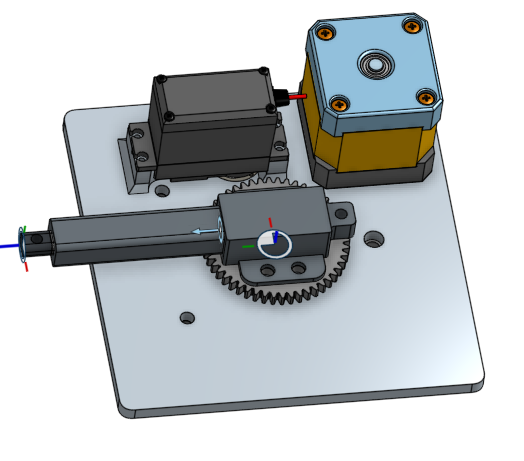 |  |
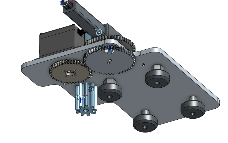
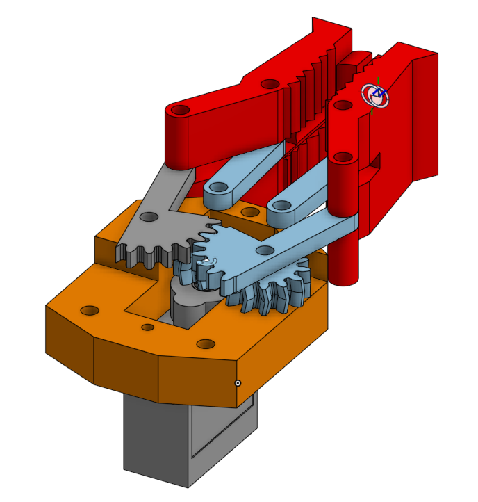
We focused on figuring out a reliable way to rotate the linear actuator.
Our first attempt was to use a gear system, where a servo drives a gear that in turn rotates a second gear connected to the actuator.
However, we were not fully satisfied with this solution. It felt too complex and introduced too much potential for failure.
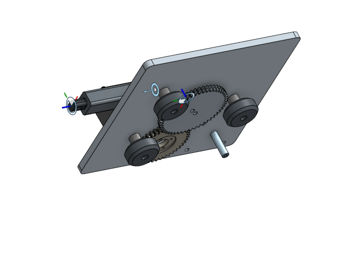
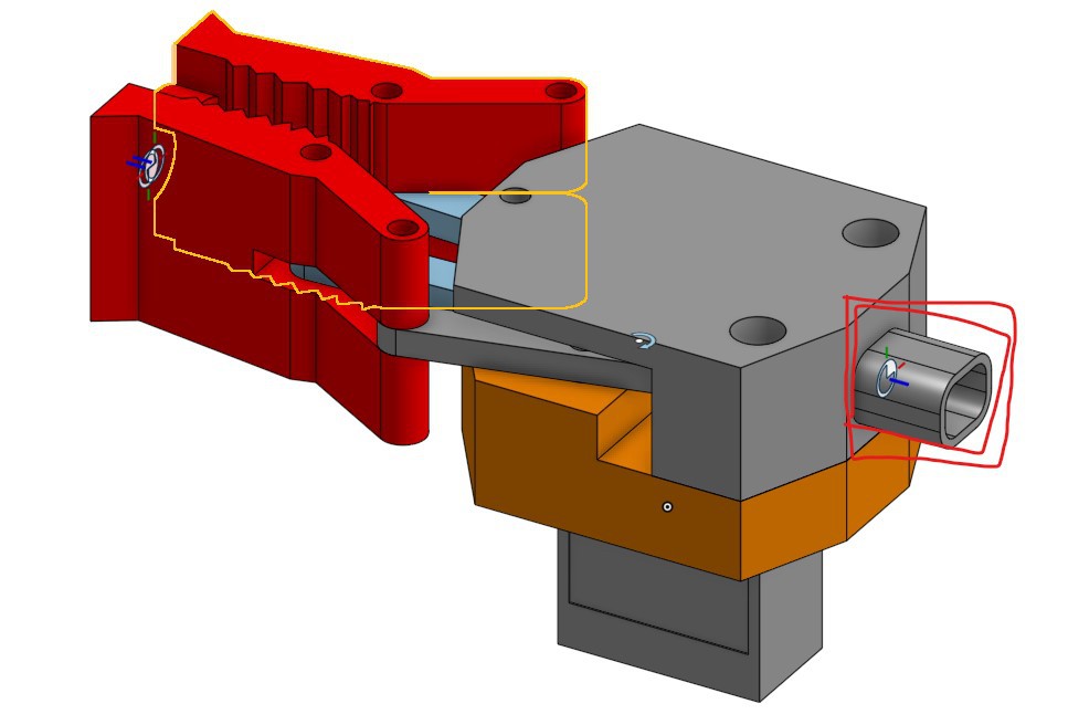
We then developed a third version of the cart:
 |  |
Mechanically, this iteration was similar to the second one, but we aimed to simplify the actuator rotation.
Still, the gear-based rotation system felt overly complicated.
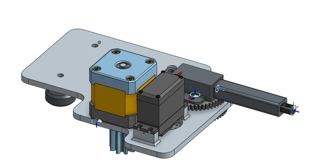
In our final design:
 |  |
We were finally satisfied with this design and decided to move forward with it.
Designing the gripper was also a crucial step.
A poorly performing gripper would make the entire machine unreliable, as it must securely grab and release the chess pieces.
We based our initial concept on this very compact design from a reference video:
Here’s our own CAD version of the gripper:
 |  |
It features a razor-like shape on each side to improve grip.
We plan to 3D print the gripper in TPU to maximize adherence and flexibility.
The gripper assembly includes a mounting interface at the bottom, designed to connect directly to the linear actuator.
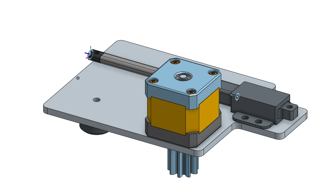
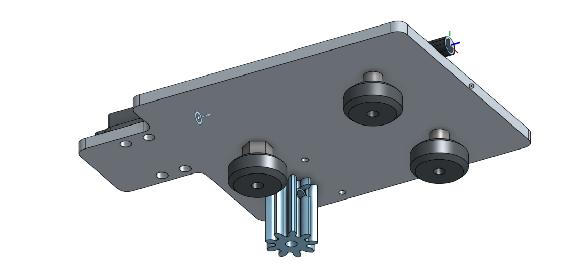
Here is the complete cart assembly :
And here’s the cart sub-assembly integrated and moving within the final full assembly :
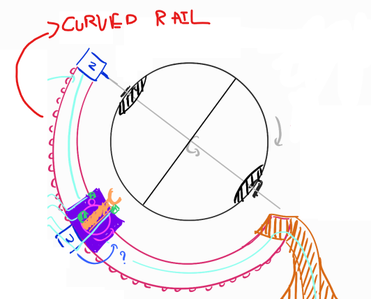
The next major component we tackled was the curved rail.
Due to its large size and the need for durability, we chose to laser-cut it from plywood/acrylic instead of 3D printing it.
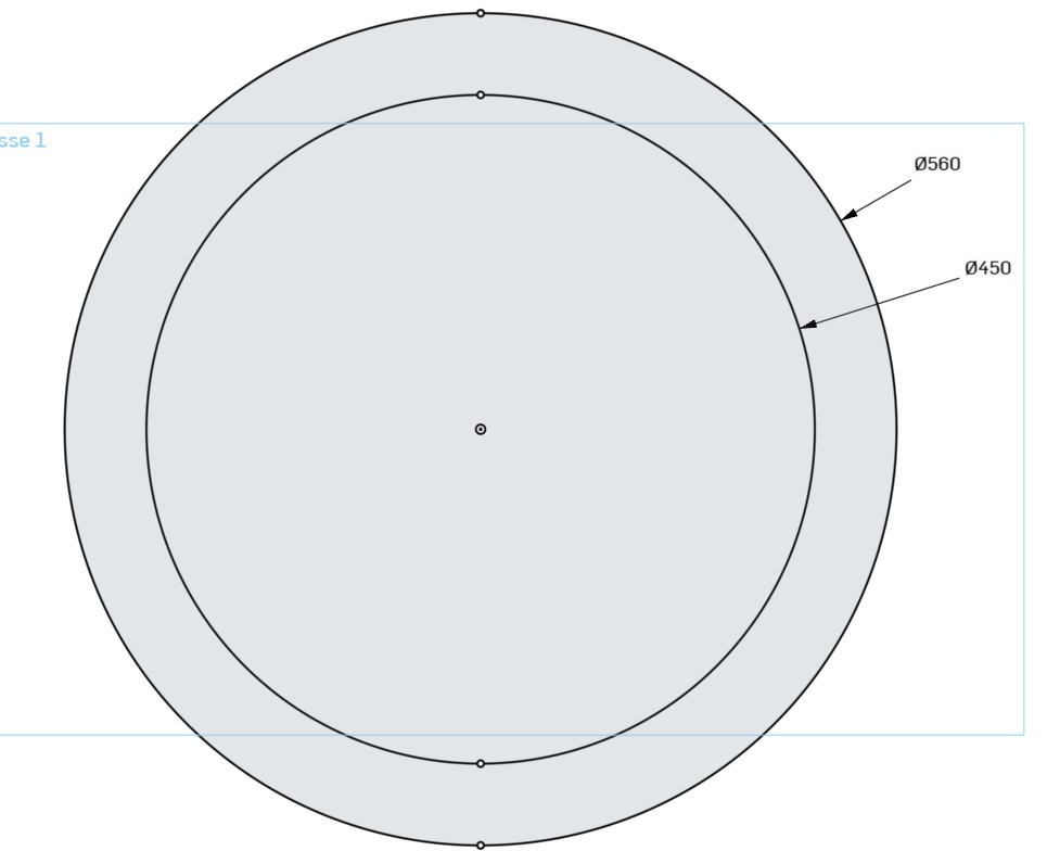
Dimensions:
Outer Diameter (OD): 560 mm
Inner Diameter (ID): 450 mm
The rail is composed of four layers, all secured together with M5 screws:
Two outer planks — 5 mm thickness each
Inner plank — 10 mm thick, this is the guide surface where the cart wheels will slide
External gear layer — 5 mm thick, this gear will be driven by the cart to move along the curve
The design of this driving system is inspired by this mechanism:
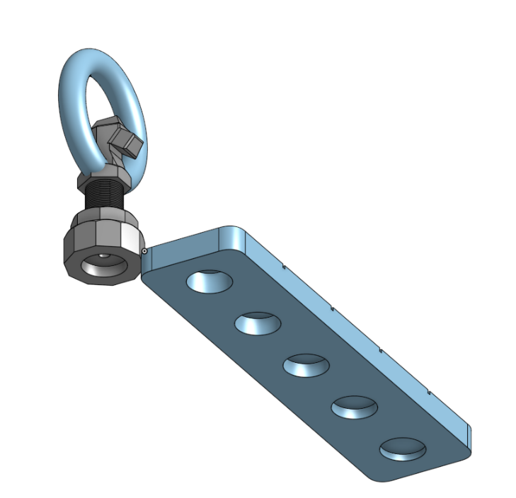
To hold the rail we designed those two piece :
 |  |
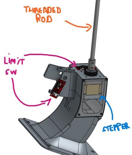
The rail "Feet" is a very important part, it house the chessboard stepper motor, the cart and the orb limit switch.
It connects to the rail using a m8 bolt
As we're using stepper motors to move the cart and chessboard, we should be able to achieve a high degree of accuracy when moving to a position, but one problem with stepper motors is that, being an open-loop system, they wouldn't know, for example, where they are at start-up.
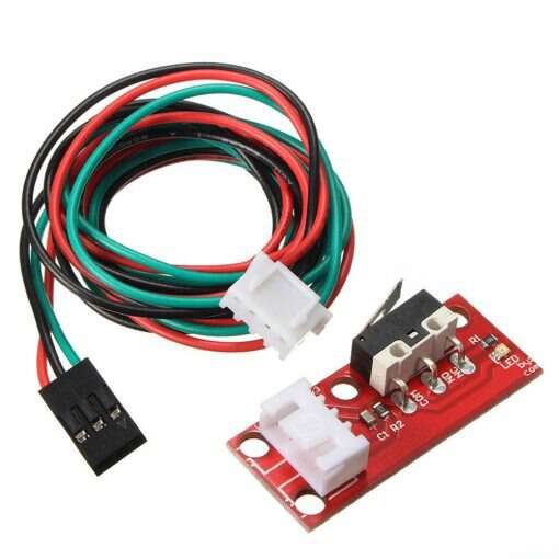
To solve this problem, we used limit switches in the path of each motor so that they could have a base (reference) position.
Here's the limit switch for the chessboard and the cart :
CHESSBOARD  | CART |
The Top part help to complete the assembly
It also connects to the rail using a m8 bolt
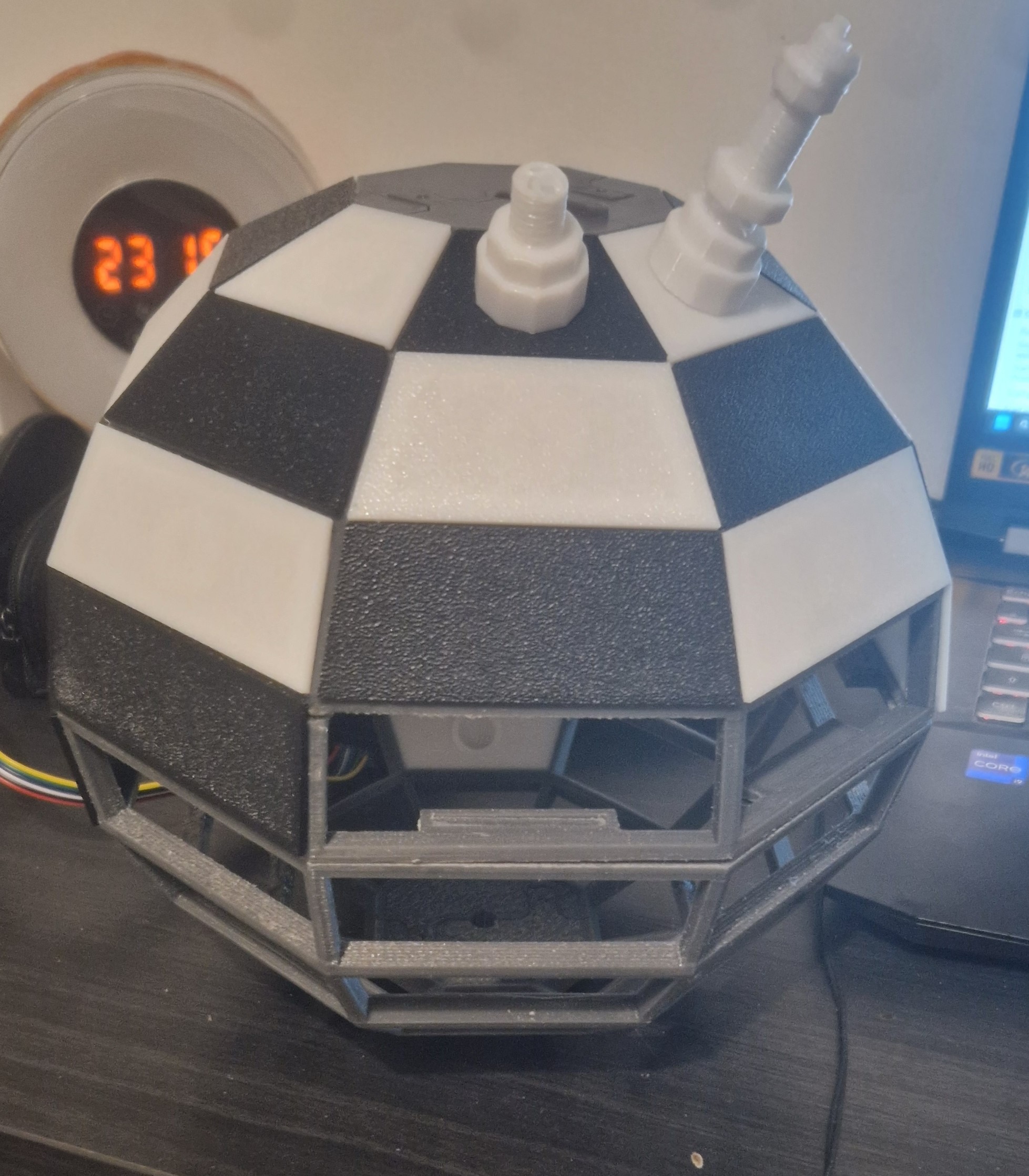
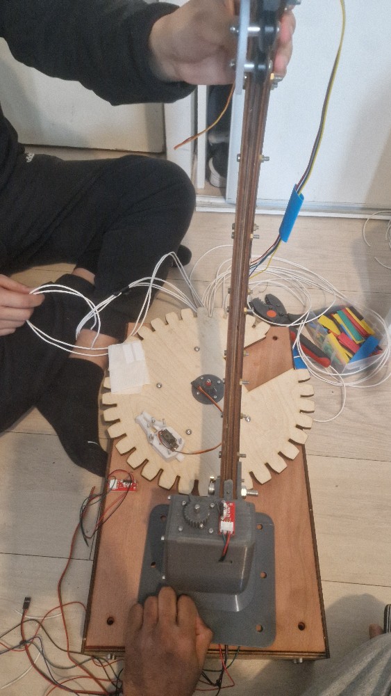
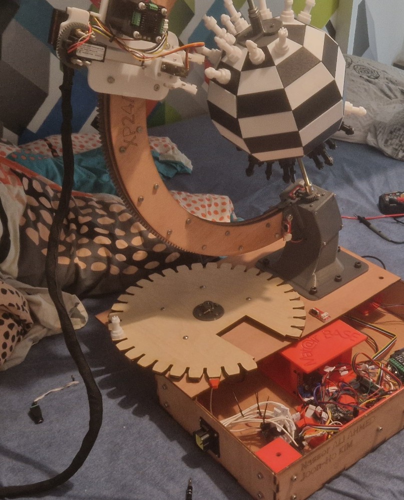
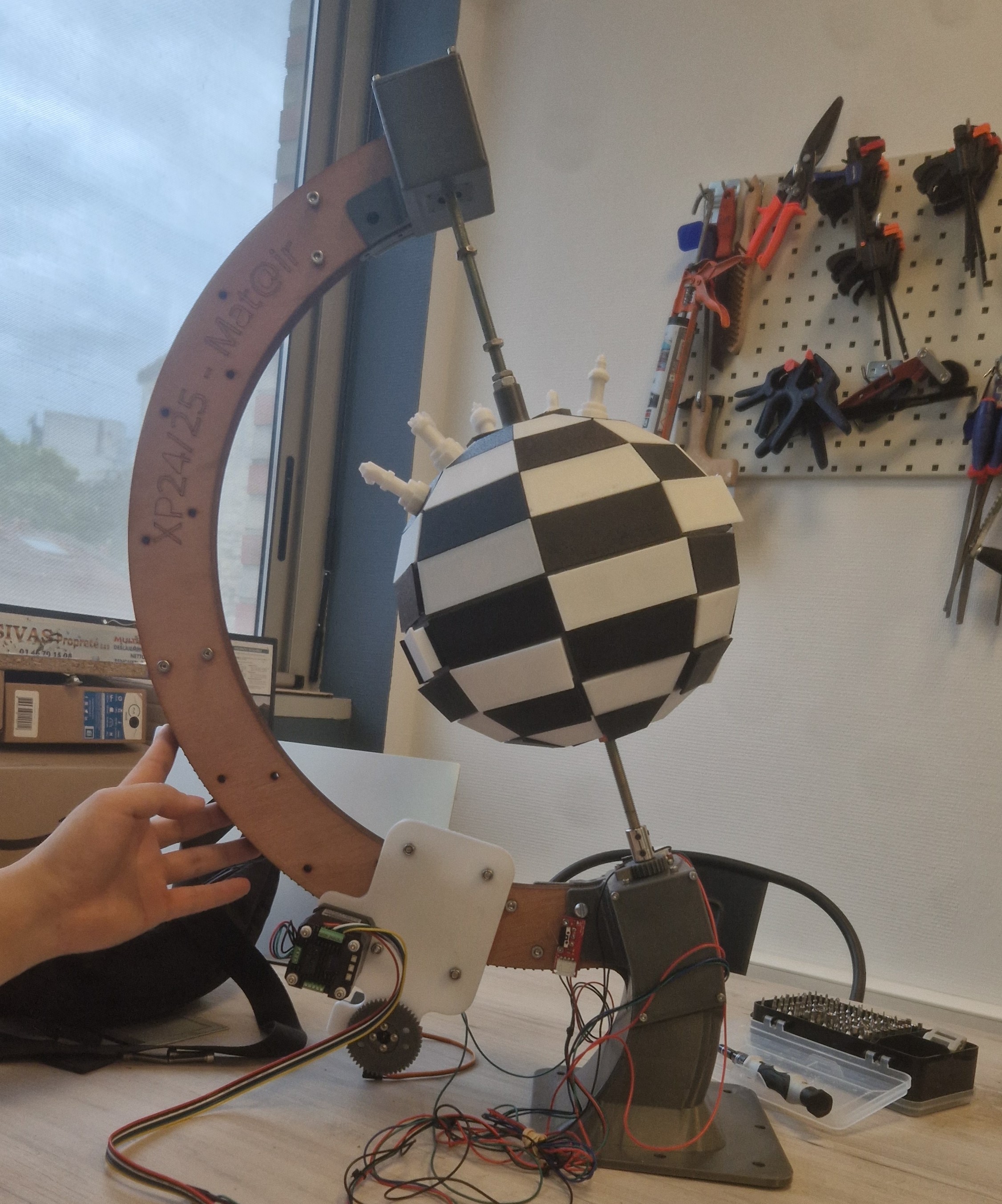
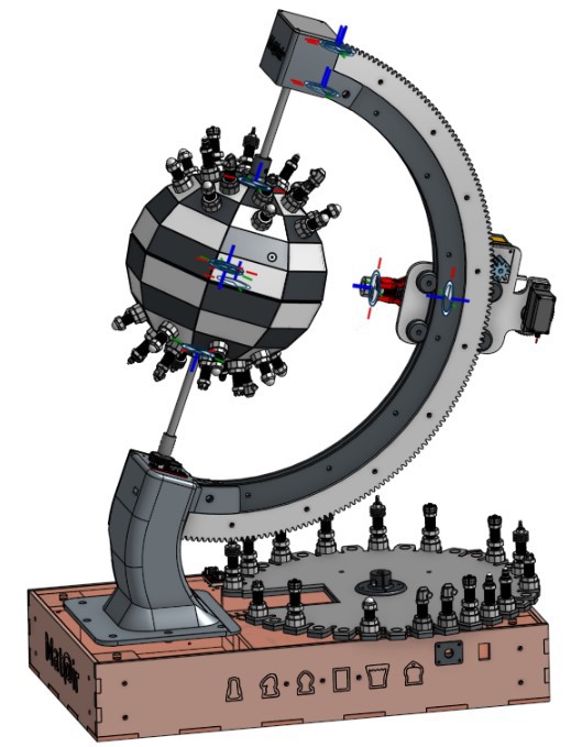
Here is the final assembly showing the curved rail, feet and top parts, stepper motor, the spherical chessboard, and the chess pieces:
Next, we modeled the chess pieces: King, Queen, Rook, Knight, Bishop, and Pawn. They are about 40mm ± 15mm tall with 20mm diameter bases. We gave them similar profiles so the gripper can grab any of them reliably. Each piece has a 12mm hole at the bottom for a magnet.
Here are some of our design for the chess piece:
| KING | QUEEN | KNIGHT |
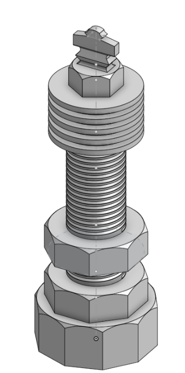 | 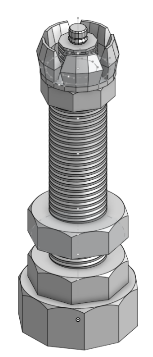 | 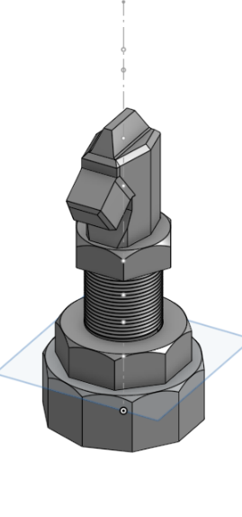 |
| PAWN | BISHOP | ROOK |
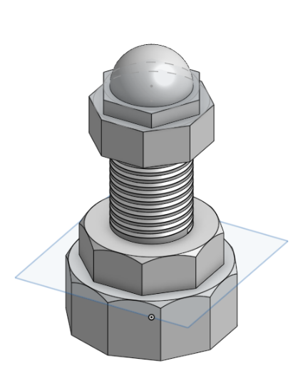 |  |  |
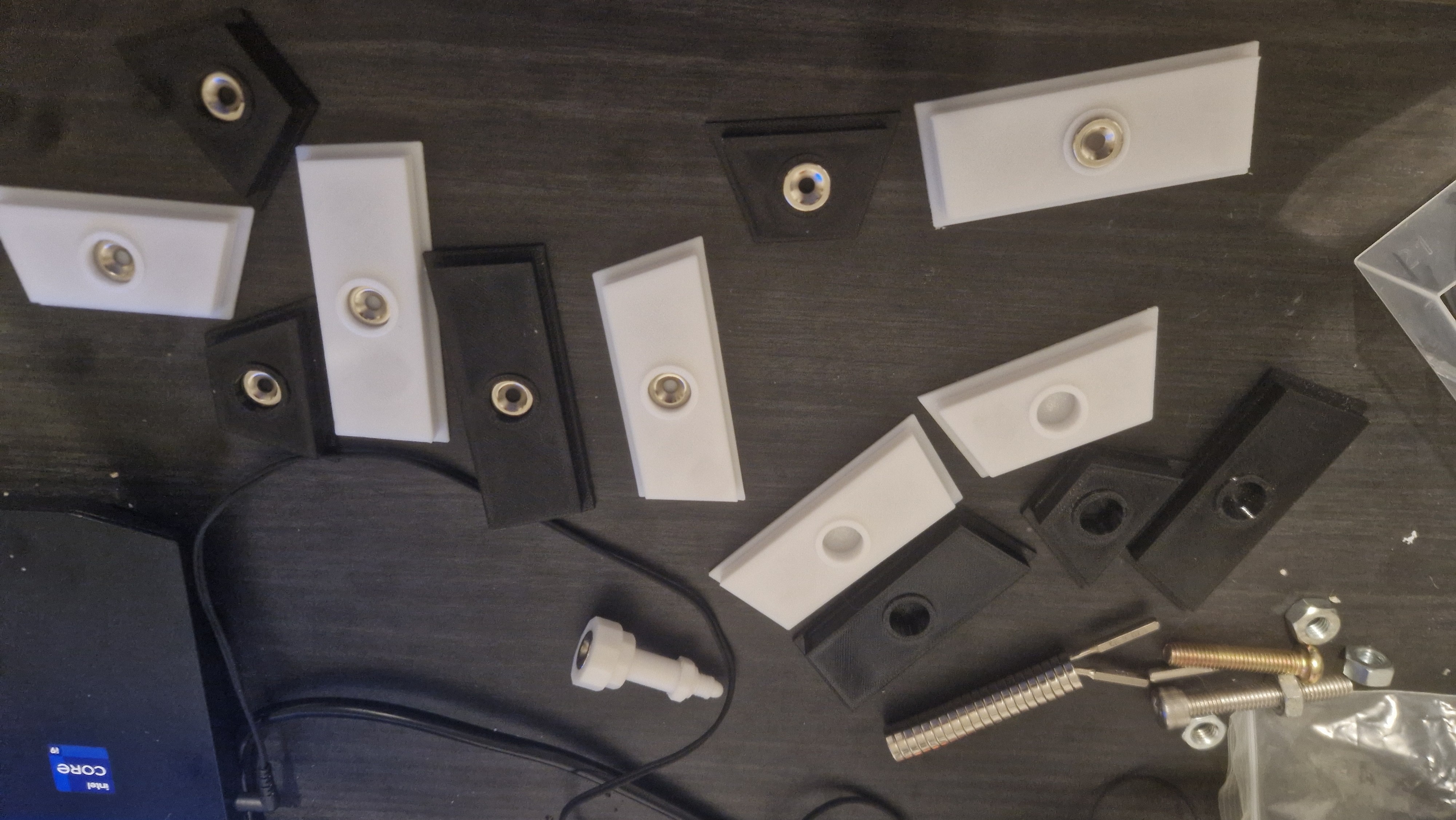
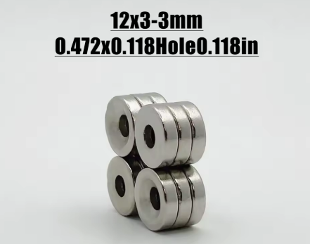
We used magnets to keep the pieces on the board and help them self-center. We needed 128 magnets total: 32 for the pieces, 64 for the squares, and 32 for the capture zone. We chose 12mm x 3mm neodymium magnets with a center hole so we could screw them in instead of using glue
Because neodymium is so strong, we had to find the right amount of plastic to put between the board magnets and the piece magnets. If they touch directly, they are too hard to pull apart. We needed enough grip to hold the pieces upside down during movement, but not so much that the robot couldn't lift them.
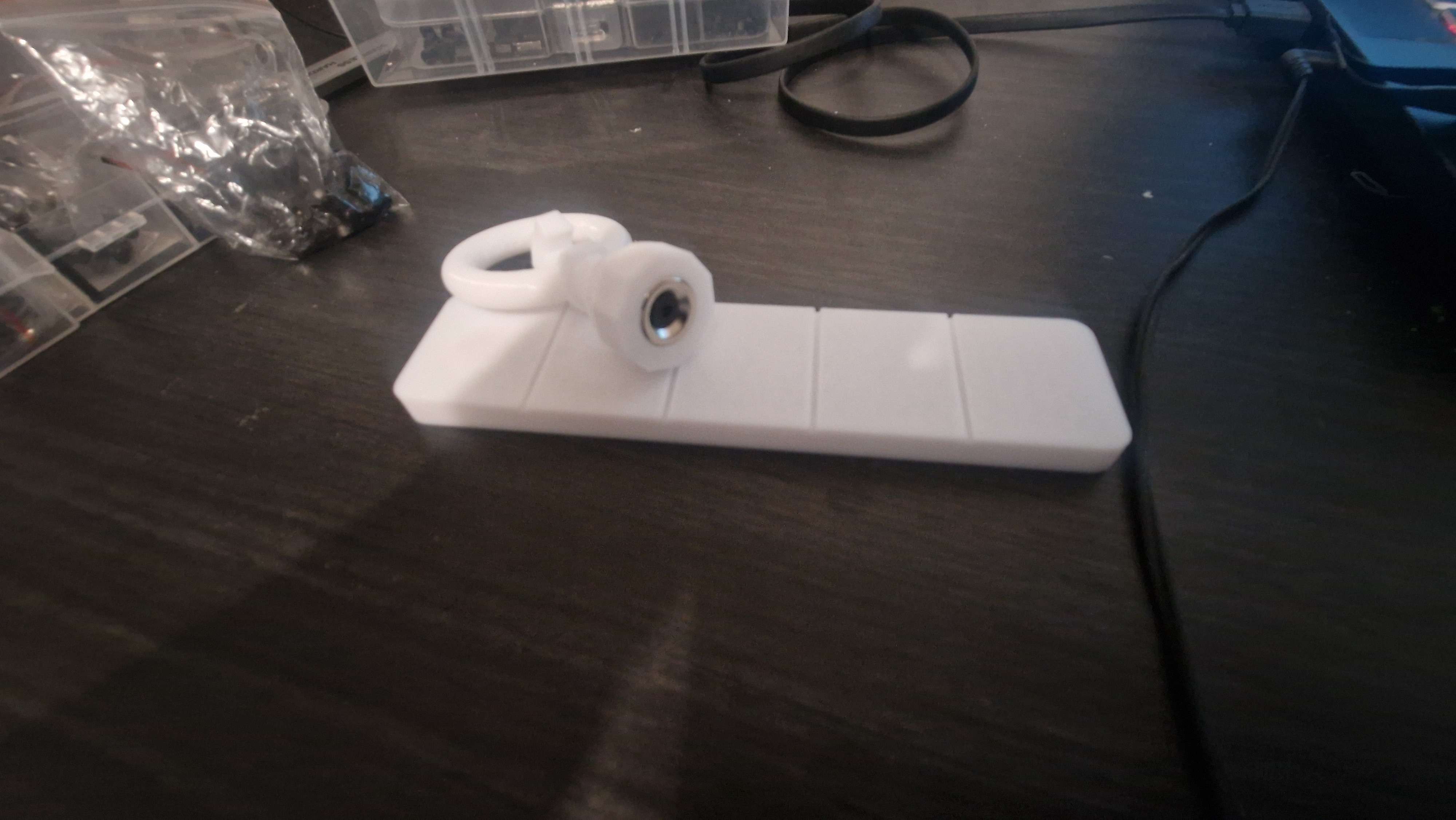
We built a test bench with plastic thicknesses ranging from 1mm to 5mm. We attached a ring to a piece and used a luggage scale to measure the force needed to pull it off. We also checked if the pieces stayed attached during abrupt movements or when held upside down
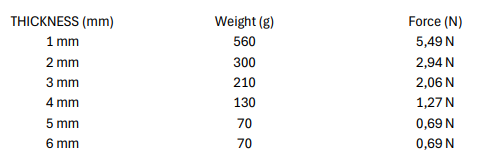
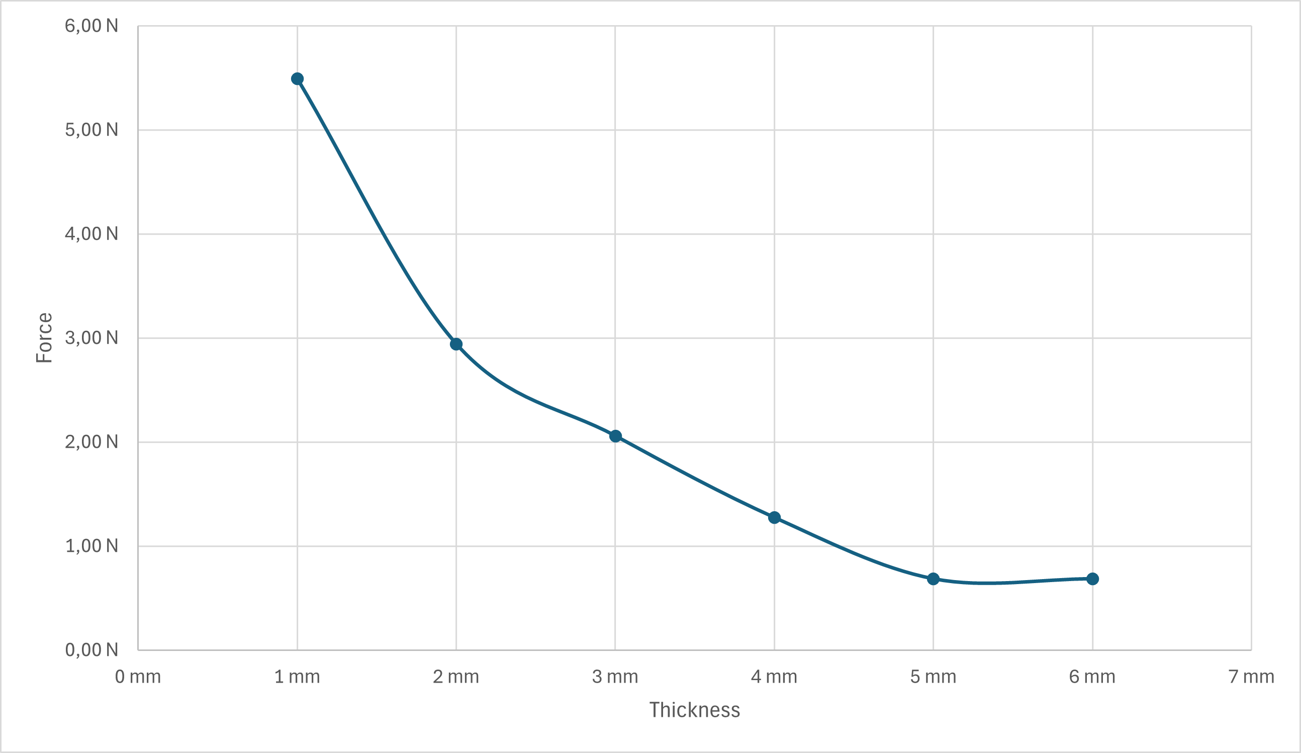
After conducting our tests, we obtained the following results:
(The infamous inverse square law is back at it again, see our log on the small hydraulic arm •_• )
With this decision, we updated the sphere design accordingly to incorporate the 3mm thickness.


 Sam Baker
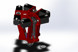
 David Brown
 Peter Sinclair
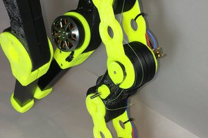
 Paul Gould