 Joseph Eoff
-
Update on the diode tester
01/10/2026 at 17:59 • 0 commentsI've finally gotten back to a state where I can reach my workbench in the attic. Pro tip: avoid breaking your leg if at all possible.
I was going to do something else entirely this afternoon, but that fell through so I ended up with time to look at the diode tester again.There were several things I wanted to do with it, so I did a couple of them.
First off, I was pretty sure that the pull up resistor was not needed. I took it out, and the diode tester kept working.
The next thing was to figure out how the 3909 could trigger the 7473 clock input. The measurements I made the last time seemed to indicate that it was not possible at all.
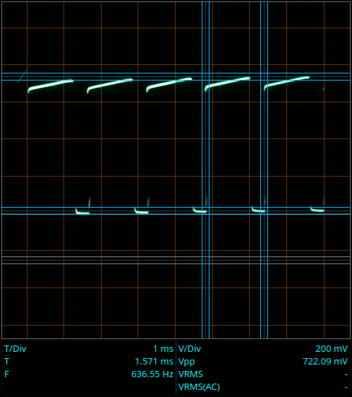
Here's a picture of the clock signal I made today:![]()
The upper trace is the 3909 power pin /7473 clock input.
The lower horizontal cursor marks the zero volt level. That puts the lower part of the clock signal at a smidge under 0.7V and the upper part at about 1.4V.
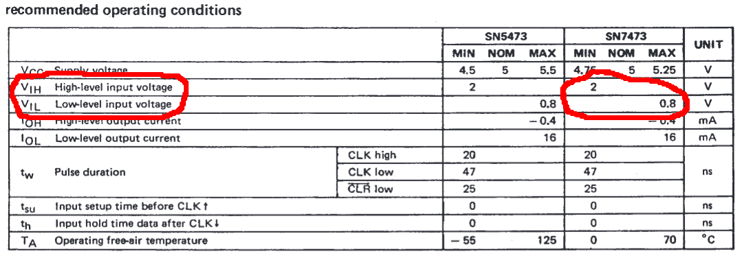
According to the 7473 datasheet (https://www.ti.com/lit/ds/symlink/sn54ls73a.pdf?ts=1768011311799) it takes a signal below 0.8V to register as a low and a voltage of 2V to register as a high.
It's getting the low OK, but is still out of specification on the high.
I had expected to find the clock signal waffling around higher than 0V, but I expected it to at least cross the official high and low voltage levels. It is waffling around at neither properly low nor properly high as expected, but it isn't even crossing both levels.
I mean, I know this thing is abusing the ICs all over the place, but I had hoped that it would al least meet some of the specifications.
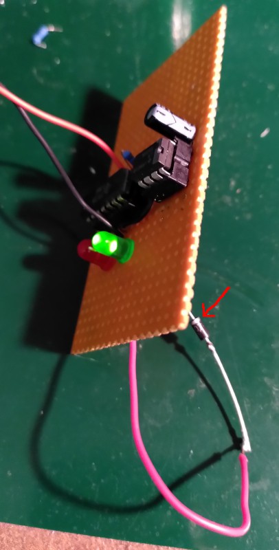
While writing this up, I left the diode tester connected to the oscilloscope and running. That took a while, and that drained the (half dead) battery I was using. It turns out that the 7473 will keep ruinning all the way down to 2.75V from the battery. Since the clock input is still "high," the 3909 keeps running as long as the battery voltage is above 1V.
The LEDs no longer longer light at that voltage, of course.Here's the 7473, clocking along with a battery voltage under 3V:
![]()
The lower trace is the 7473. The trace is on 2V per division rather than 1V per division for the upper trace. At that point, the LED was still blinking.
That makes me wonder if you could run an old fashioned 7473 on 3.3V, and whether it would still meet its specifications. Hmmm. A project for another day.
-
Closing
11/09/2025 at 09:14 • 0 commentsI've submitted this project to the Component Abuse Challenge.
I had some further experiments and measurements I wanted to do, but life has a way of changing our plans.
In this case, changed plans means it'll be at least one month, more likely two before I can get back to my electronics work bench.
Some of the things I wanted to try:
1. Remove the pull-up on the JK inputs. My memory says the original circuit didn't have it. Both inputs should float high, and with them connected together, the toggle function should be enabled without the pull up. The sketch I found shows the pull-up, but it was drawn at least 20 years after my dad built the first one.
2. More accurate measurements of the clock signal. The clock signal is very low, and doesn't come close to meeting the input specifications of the 7473. I want to be sure what it is really doing.
3. Restore the blinking "power on" LED. The original had the LED on the 3909. It let you know the circuit was on and that the battery wasn't dead. You needed that to be sure of an open "diode under test" (DUT) when neither of the test LEDs lit up. Power on LED lit, DUT connected, no test LEDs lit = diode failed open.
4. Test on 5V, test on 9V from a power supply. I have assumed that the lower current from the carbon zinc battery protected the 7473 somewhat. That may not, however, be true. I built one diode tester combined with a 9V power supply. The diode tester was powered from the 9V supply. As a school project, I built a 9V DC power supply to use for my projects. 110VAC to 9VDC. Completely linear - transformer, diode bridge, 7809, filter capacitor. The benchtop power supply had a diode tester built in. My memory swears that the diode tester was powered by the 9V output.
---------
The idea to use the 3909 came later. Radio Shack sold blinking LEDs at the time. The first version of the diode tester had a blinking LED connected to the clock input of the 7473. Since the LED blinked at like once per second, the test LEDs also alternated slowly. My dad wanted to have the appearance of both LEDs lighting simulataneously, so he needed a faster oscillator.
Radio Shack's "documentation" (description on the back of the package) for the blinking LEDs said that they had an integrated LM3909 for the blink function. I don't know if that's true, but my dad took them at their word. If the blinking LED could trigger the 7473 clock, then an LM3909 ought to do it as well - and it did.
At least one of the diode testers my dad built used a dual red/green LED. Both in one housing, just two pins with the two LEDs in antiparallel. When driven with a (relatively) fast AC signal, it would glow yellow. With that version of the diode tester, you had "yellow" to indicate a shorted diode.
-
Living with abuse
11/09/2025 at 08:39 • 0 commentsAfter showing how abusive this circuit is, it is now time to explain how it survives and functions despite the abuses.
1. Powered by a 9V transistor radio battery with no regulator. The 7473 receives 9V from the battery (the absolute maximum for the 7473 is 5.5V)
There are two things that go into making this work:
- The note by the battery "9V carbon zinc"
- Robustness of the IC
Carbon zinc 9V batteries have a fairly high internal resistance. The output voltage of the battery drops when loaded. If the IC tries to draw a current that could damage it, the battery simply drops the voltage. During my experiments, the voltage from the battery dropped to around 7V. That is still high, but then the robustness of the IC comes into play
The IC is rated for 5V, but there's nothing inside it really requires exactly 5V. All of the transistors will have a VCE of more than 5V. How much more, no one can say without destructive testing. More than 5V, certainly. More than 7V? Obviously, because it ran with that voltage on my workbench. More than 12V? Try it and see.
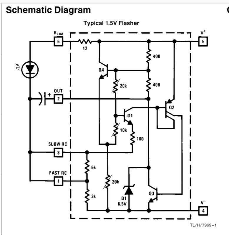
2. The LM3909 LED blinker IC has no LED to blink.The LM3909 datasheet (https://cdn.hackaday.io/files/291791248394336/LM3909%20Datasheet%202.pdf) shows the internal circuit of the IC.
![]()
The LED plays no part in the oscillator. It runs just fine without the LED.
3. The LM3909 is powered by the leakage current from the 7473 clock input. The datasheet says it needs a minimum of 1.15V to operate. It is operating here on something less than 1V.
This is down to design specifications. The 3909 is guaranteed to operate down to 1.15V. What is does below that is not specified. If it works, cool. If not, the manufacturer just says "Oh, well. Tough. The 3909 isn't specified for that." Practically, the LM3909 blinkers were used with a single 1.5V cell, and ran to exhaustion. If it ran with a battery discharged below 1.15V, fine. So much the better. It just wasn't guaranteed.
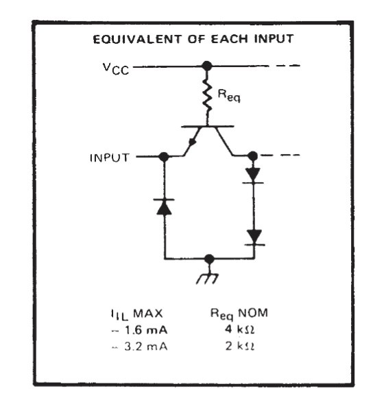
As for just where the power comes from, that is given by the design on the inputs on the 7473:
![]()
The clock input is the emitter of an NPN transistor. Current flows from VCC, through Req, through the base of the transistor, and out of the clock input. Depending on the exact value of Req, you get anywhere from 1.6mA to 3.2mA out of the input. The LM3909 datasheet says it draws a maximum of 0.75mA. That load pulls the voltage down considerably, but still leaves enough voltage for the 3909 to operate (though far outside of its specifications.)
4. The clock signal to the 7473 is a 0.7V peak to peak signal. By the datasheet, a low is maximum 0.8V and a high is minimum 2V. Somehow, 0.7V is enough to trigger the clock.
I strongly suspect that the 0.7V does not oscillate between 0 and 0.7V, but rather that it bounces between something just over 0.8V and something somewhat below 0.8V. I needed to check the offset on the clock signal, but didn't do it. I won't be able to get to my workbench to check this before the contest deadline, so this will have to remain speculation for now.
5. There's no decoupling capacitor for the 7473.
For TTL circuits, it is recommended to have a 100nF capacitor across the power leads of each IC. In this case, it isn't needed. The decoupling capacitor is there to prevent power rail glitches from a fast switching IC from disturbing other ICs. There are no other TTL ICs in this circuit, and no fast signals at all. We can safely leave out the decoupling capacitor.
6. The 7473 is driving the LEDs directly, with no current limiting resistor. This exceeds the output current limit for the 7473.
7. The LEDs are driven directly from the 7473 with no current limiting. This exceeds the LED current limits.
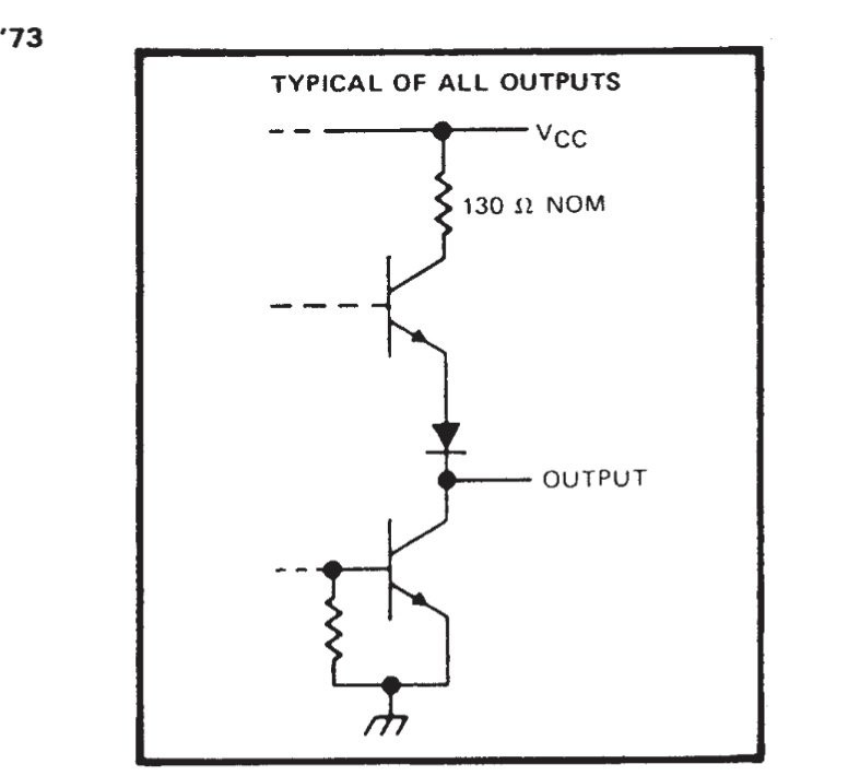
These two have a common cause: The output circuit of the 7473:
![]()
That resistor up there is what allows the output and the LEDs to survive. That, and the forward voltage of the LEDs.
The LEDs have a forward voltage of about 2V. Taking the 7V battery voltage, subtracting the foward voltage of 2V, Ohm's law says there'll be 38 milliamperes through the 130 ohm resistor in the IC.
The datasheet further notes that a "high" output will usually be lower than the supply voltage of the IC. That, of course, reduces the output current.
The LEDs get a final bit of help in that they are pulsed. They light up in alternation, each one only lit for half of the time. They have less time to heat up, so are less likely to fail - even in the unlikely case that they do get a really high current.
-
How many abuses are there in this circuit?
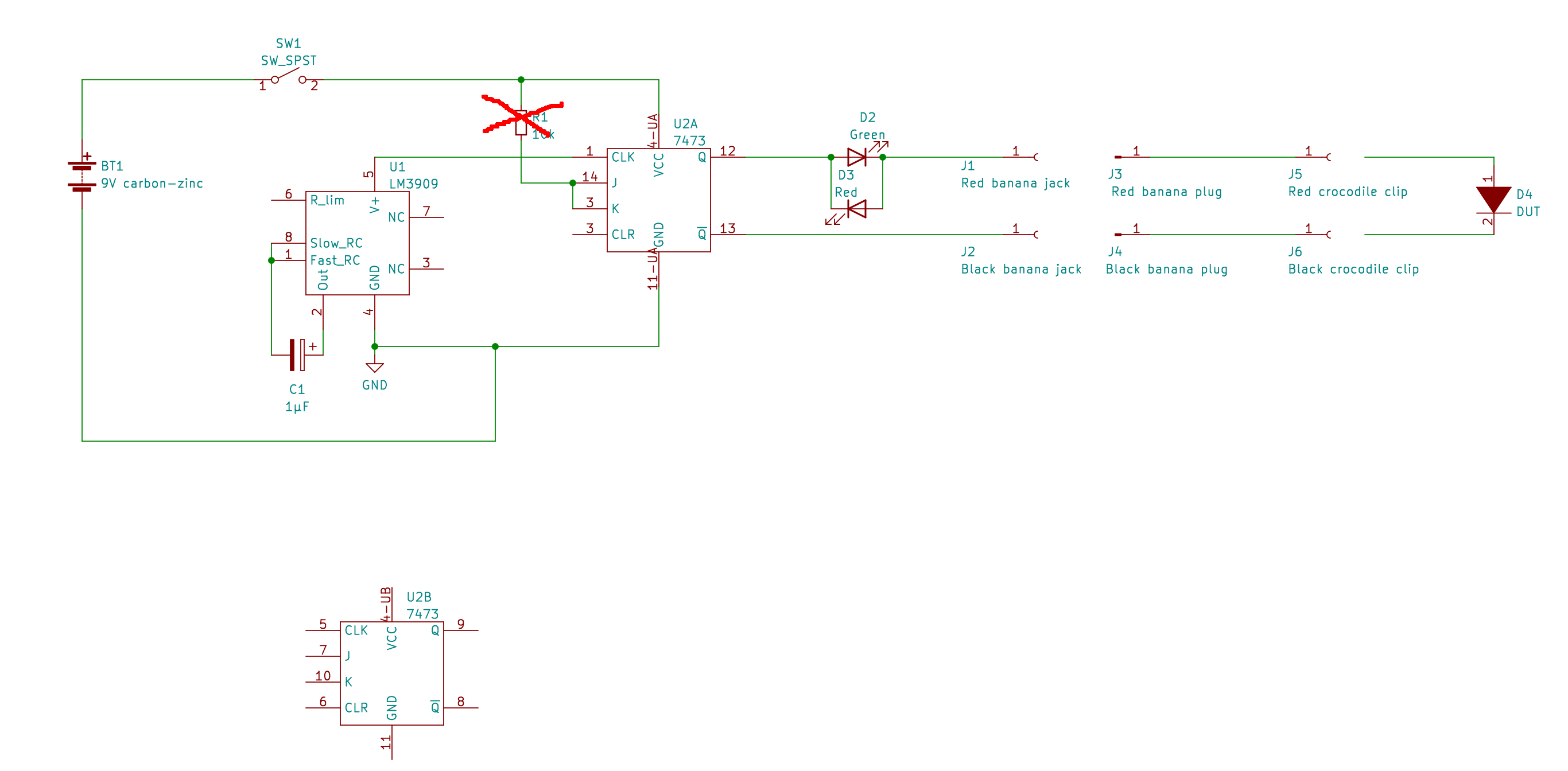
11/05/2025 at 22:03 • 0 commentsHere's the circuit again:
![]()
Let's count the abuses in the circuit.
Starting from the left:
- Powered by a 9V transistor radio battery with no regulator. The 7473 receives 9V from the battery (the absolute maximum for the 7473 is 5.5V)
- The LM3909 LED blinker IC has no LED to blink.
- The LM3909 is powered by the leakage current from the 7473 clock input. The datasheet says it needs a minimum of 1.15V to operate. It is operating here on something less than 1V.
- The clock signal to the 7473 is a 0.7V peak to peak signal. By the datasheet, a low is maximum 0.8V and a high is minimum 2V. Somehow, 0.7V is enough to trigger the clock.
- There's no decoupling capacitor for the 7473.
- The 7473 is driving the LEDs directly, with no current limiting resistor. This exceeds the output current limit for the 7473
- The LEDs are driven directly from the 7473 with no current limiting. This exceeds the LED current limits.
By all rights, the 7473 should just go "pop" and give up the ghost as soon as it is turned on. It doesn't.
The 7473 should burn out its outputs, driving current into a short circuit when the diode under test is bad. It doesn't.
The LEDs should go "pop" when the output is shorted. They don't. They blink happily.
The LM3909 shouldn't oscillate at all since it has no real power supply and what it does get is completely outside of the specifications. It runs.
The 7473 shouldn't react to the flaky clock signal from the LM3909. It does.
Some of that I can explain, some of it I can't.
The parts of it I do understand, I'll explain in a later post.
-
LED waveforms
11/05/2025 at 21:44 • 0 commentsSince I had the prototype and the oscilloscope both at hand to check the oscillator signal, I went ahead and checked the LED signals.
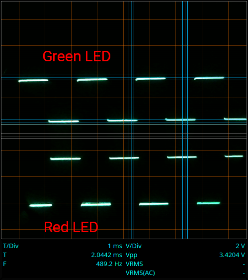
The 7473 does a pretty decent job of squaring up the funky edges of the LM3909 signal. The outputs are nice, neat square waves.![]()
Each alone wouldn't do you much good. The trick is when you connect the LEDs anti-parallel with the diode under test in series with them.
There is effectively an AC signal across the LEDs. Putting a diode in series cuts off one half of the AC cycle, leaving only one half to drive the LEDs pair. Which ever LED "points" in the same direction as the diode under test lights up.
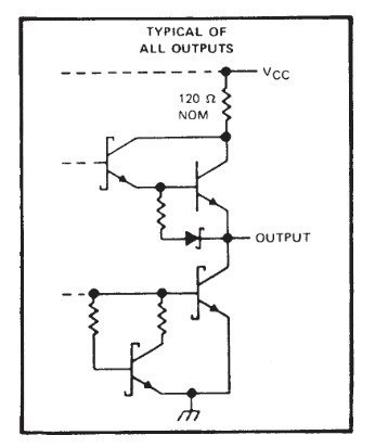
As the 7473 datasheet shows, the Q and /Q outputs of the 7473 are each effectively half an H-bridge, with the /Q driven by the inverse of the Q output:
![]()
Two half H-bridges and an inverter make a full H-bridge. If there were a (very) low powered motor in there, it would reverse direction on each pulse of the clock. Instead, there are two diodes in anti-parallel in there. They light up alternately as the clock pulses.
If you slow down the clock, you can see the LEDs light up one at a time. With the fast clock I've used, they alternate faster than the eye can see - they appear to be both on all the time when the diode under test is shorted.
-
Corrections to the schematic
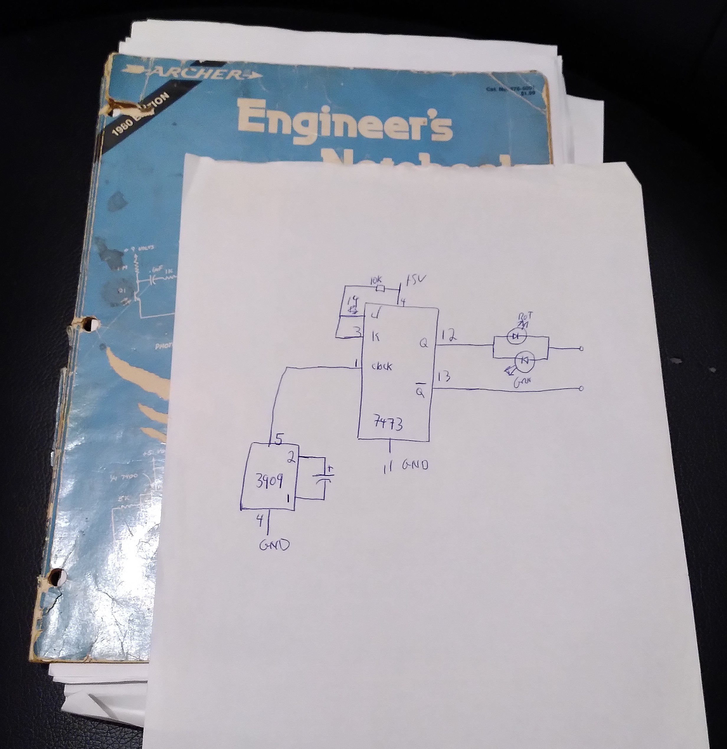
11/05/2025 at 21:16 • 0 commentsWhile trying to figure out why my new diode tester wasn't running, I found a decades old sketch of the circuit. It was stuck in between some other drawings that I had stuck in my copy of the "Engineers Notebook."
![]()
It turns out that you don't need the LED on the 3909, but you do need a pull up on the JK inputs.
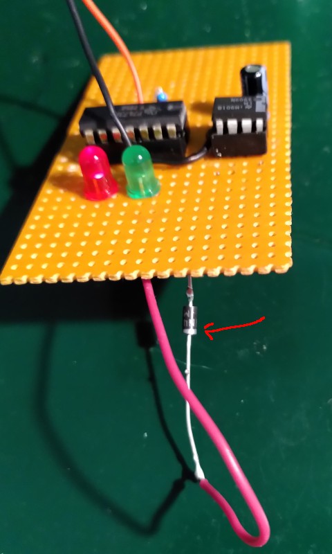
I updated my prototype and the schematic accordingly:
![]()
It is still a very simple circuit, very well suited to building on a perfboard.
If you build a copy, I recommend you use sockets for the ICs. Back in the day, we used sockets because ICs were expensive and hard to get (ever drive 40 miles to get to the nearest Radio Shack?) Sockets let you swap an IC from one gadget to another without trying to unsolder 14 pins without toasting the IC or burning the pads off the board. Now a days, the required ICs are obsolete and again hard to get. Putting the ICs in sockets lets you pop them back out if you want to build another circuit with them.
-
Persnickety oscillator
11/05/2025 at 21:02 • 0 commentsBack when my Dad made the first one of these, he didn't have an oscilloscope. I always wondered what the clock really looked like, since the LM3909 doesn't really have a power supply in this circuit. Somehow, in later years I never had a working oscilloscope and a working diode tester in my hands at the same time.
I had the chance once in high school, when I built one as a project in an electronics class. The teacher was kind of surprised at how it worked, but we didn't get around to hooking up the clock to the scope.
As it turns out, the LM3909 has good grounds to be picky. It is powered by the leakage current through the clock input of the 7473. That current is so low, that with the load of the LM3909, the clock input voltage stays way below 1 volt. The LM3909 oscillates with a peak to peak voltage of about 0.7 volts:![]()
The signal it generates isn't really very good:
- The duty cycle is very far from 50 percent.
- The edges are not especially fast.
- The top is still rising across the whole "high" period.
Scuzzy as it is, it does run - but only if you use a 7473.
-
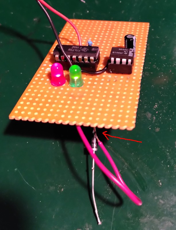
Recreating the prototype
11/05/2025 at 20:39 • 0 commentsI built a prototype a few weeks ago, but couldn't get it to work.
There were two things wrong:
- An incorrect wire
- An incorrect IC.
I managed to short circuit the indicator LEDs when I put them in. Had a simple brain fart, and wired two pins together that shouldn't be connected.
For the incorrect IC, I used a 74LS73 instead of the original 7473 - no LS or other designators in the middle. I happened to have a single 74LS73 in a junk box in the attic. When it didn't work, I ordered some real 7473s from eBay - I guess I got lucky, because they do work.
Here's the prototype showing a good diode connected the right way around:![]()
Only the green LED is lit.
Here it is with the diode under test connected backwards:
![]()
Only the red LED is lit.
Here's a short circuit:
![]()
Both LEDs are lit.
The prototype works as it should.
With the 74LS73, the oscillator (the LM3909) mostly wouldn't start. If I touched anything connected directly to the 3909, it would fire up. That's (sort of) workable if you are just playing around, but definitely not something you want in a working tool.
-
Recreating the schematic diagram
10/03/2025 at 10:23 • 0 commentsWay back in 1980, my dad didn't have a program for drawing circuit diagrams. Heck, we didn't get a home computer (a used TRS-80 Model 1, level II) until a few years later - and it couldn't have been used to draw a schematic diagram.
My dad's hand drawn diagrams disappeared decades ago.
I've recreated them from what I remember and by referring to the "Engineer's Notebook" from Forrest M. Mims. That's the book my dad used when making the diode tester, since we didn't have datasheets or any other kind of documentation.My copy of the "Engineer's Notebook" is the later one with the blue cover from 1980 rather than the first printing from 1979 with the yellow cover.
I used KiCAD to draw the circuit as best I can remember it.
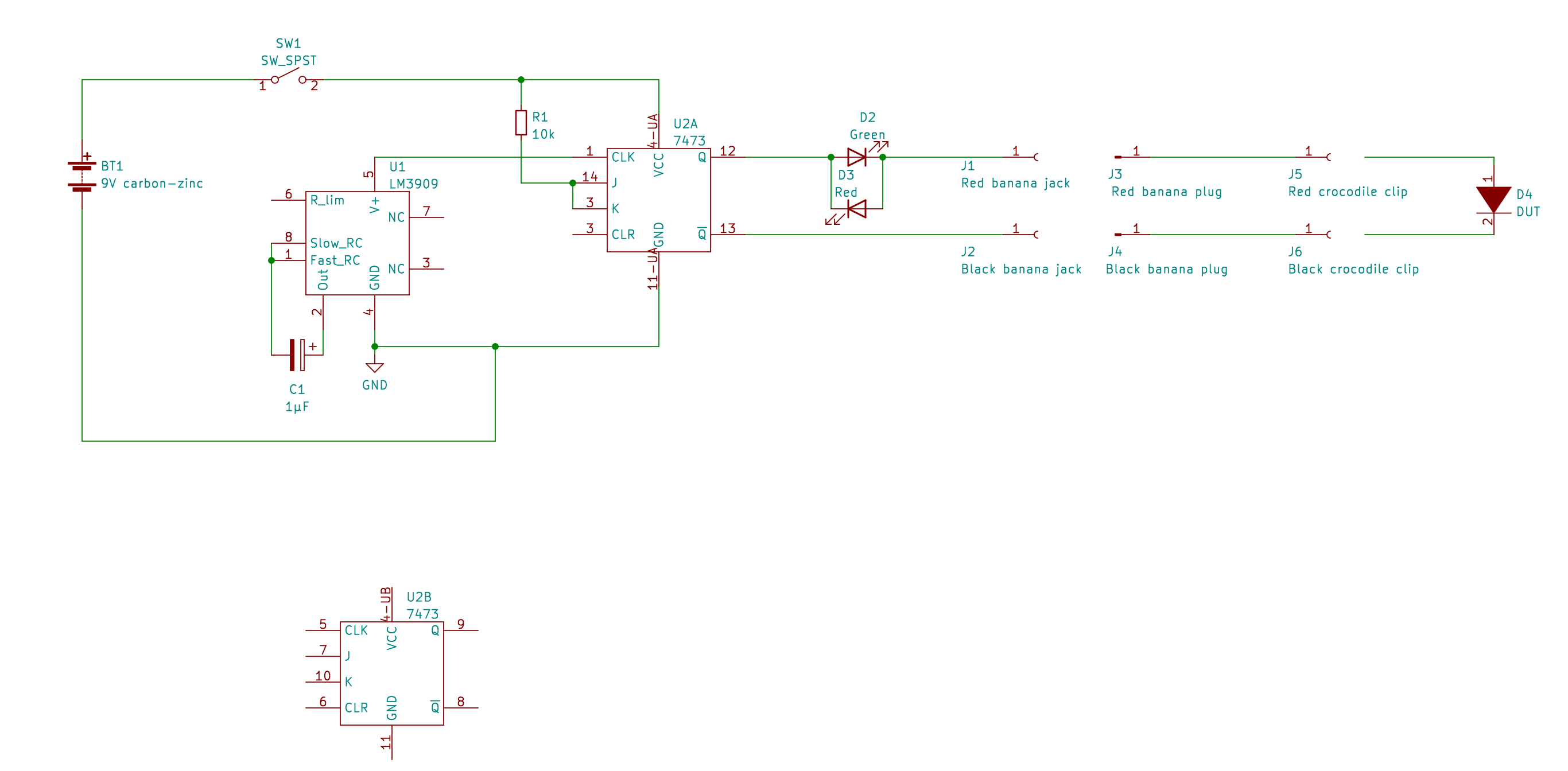
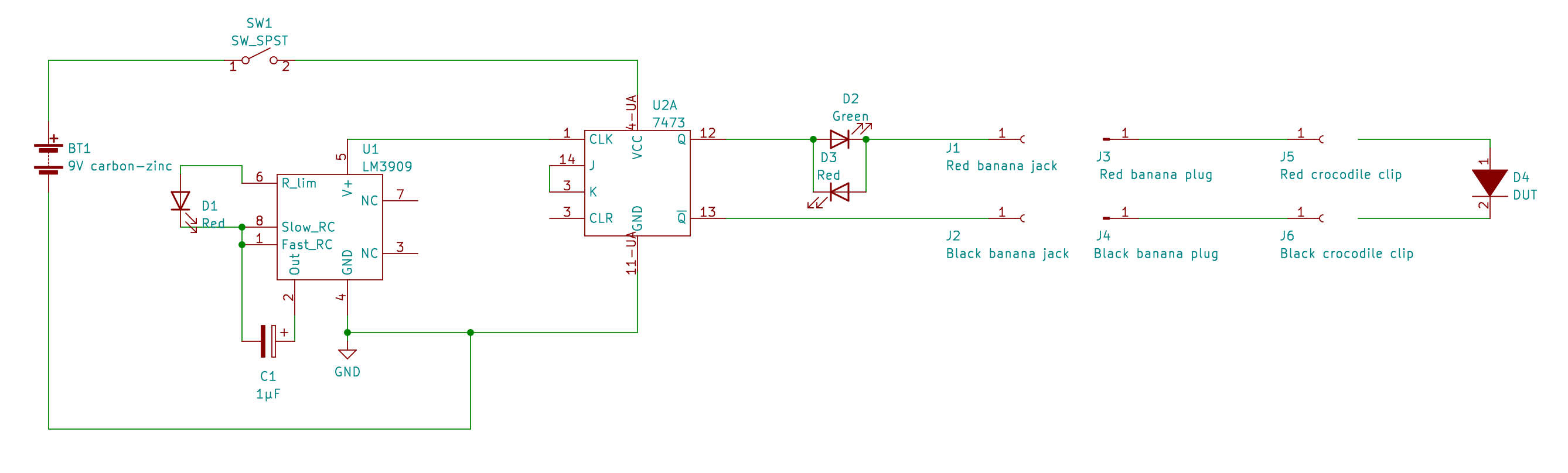
Here's the schematic:
![]()
The idea is simple:
1. On the left is a battery that powers the circuit.
2. There's an LM3909 as an oscillator driving the clock of a JK flip-flop.
3. The JK flip-flop is set to toggle its outputs by connecting the JK inputs together.
4. The Q and /Q outputs swap state on every clock pulse.
5. Viewed between Q and /Q, you have an AC square wave.
6. There are two LEDs (D2 and D3) in anti-parallel in series with the device under test.
7. The DUT will remove one half of the AC cycle. If it is connected in the same direction as the green LED, then only the green LED will light. Same with the red LED. If the DUT is open, then neither LED lights. If the DUT is shorted then both LEDs will light
8. LED D1 is part of the oscillator circuit, but also indicates power on so that you can tell the difference between open DUT and dead battery.
So far, so good.
It really does work. My dad built several of them for work. I built a couple of them myself for an electronics course in highschool and later for other projects.
It is how it does it that is really messed up.
Look it over and see how many ways the ICs and LEDs are being abused.
I'll put a list of all of the abuses in a later log. See if you can find them all.
-
Making Parts
09/18/2025 at 19:50 • 0 commentsI sat down this evening to start the project - project page on Hackaday.io, schematic, etc.
It turns out that before I can draw the schematic, I have to first make symbols in KiCad. The LM3909 is obsolete, and the TTL 7473 has been replaced by updates to other technologies (LS and HCT). Neither part is in the standard KiCad libraries.
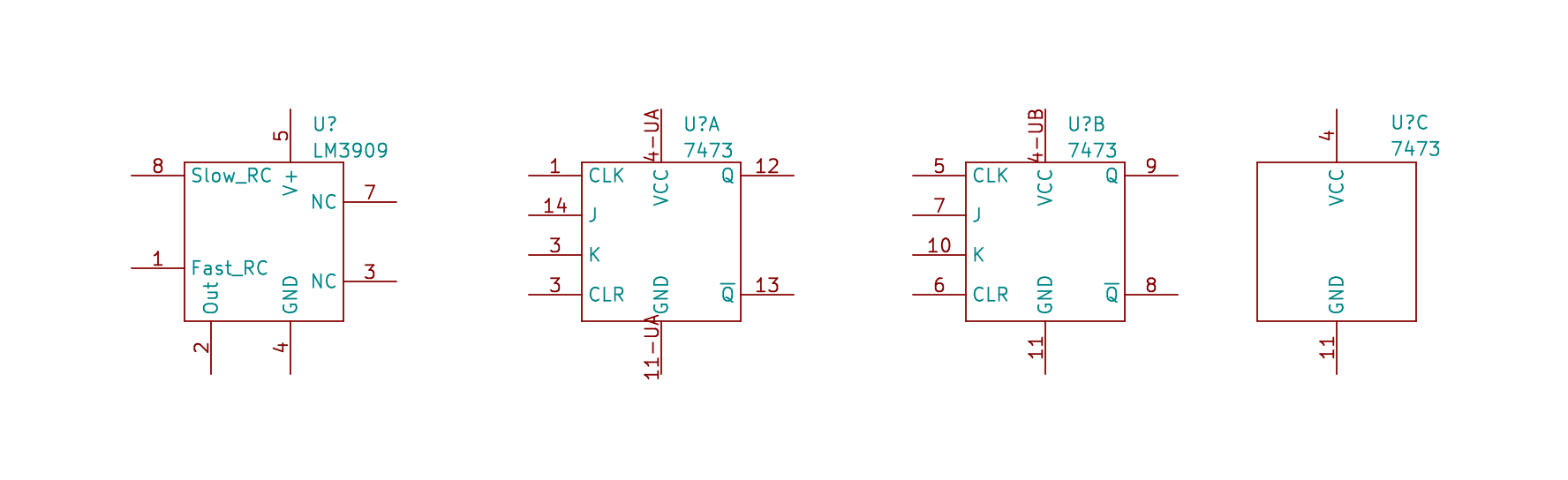
Here are the symbols I drew up:
The 7473 has two flip-flops, unit A and B. The symbol has a third unit just for the power connections.
While perusing the datasheets to make the symbols, I discovered that the circuit my dad created way back then abuses the IC rather more than I thought. I'll explain all of the abuses in a later log post.
The IC abusing diode tester
Mistreating an LM3909 and a 7473 to test diodes - a recreation of a 40 year old device.
 The next thing was to figure out how the 3909 could trigger the 7473 clock input. The measurements I made the last time seemed to indicate that it was not possible at all.
 I had expected to find the clock signal waffling around higher than 0V, but I expected it to at least cross the official high and low voltage levels. It is waffling around at neither properly low nor properly high as expected, but it isn't even crossing both levels.

 The 7473 has two flip-flops, unit A and B. The symbol has a third unit just for the power connections.