 Vittorio Lumare
-
1Assembly : Initial Empty Skeleton
The names of the holes and other parts are defined in the chapter Nomenclature of Parts.
The assemblage consists taking the hand’s skeleton and to install on it all the components following a precise sequence.
IMPORTANT: If the sequence is not followed correctly, all components already installed will have to be dismantled till the moment the sequence was modified, in order to resume again the proper order of the sequence because there are parts that cannot be assembled after others.
-
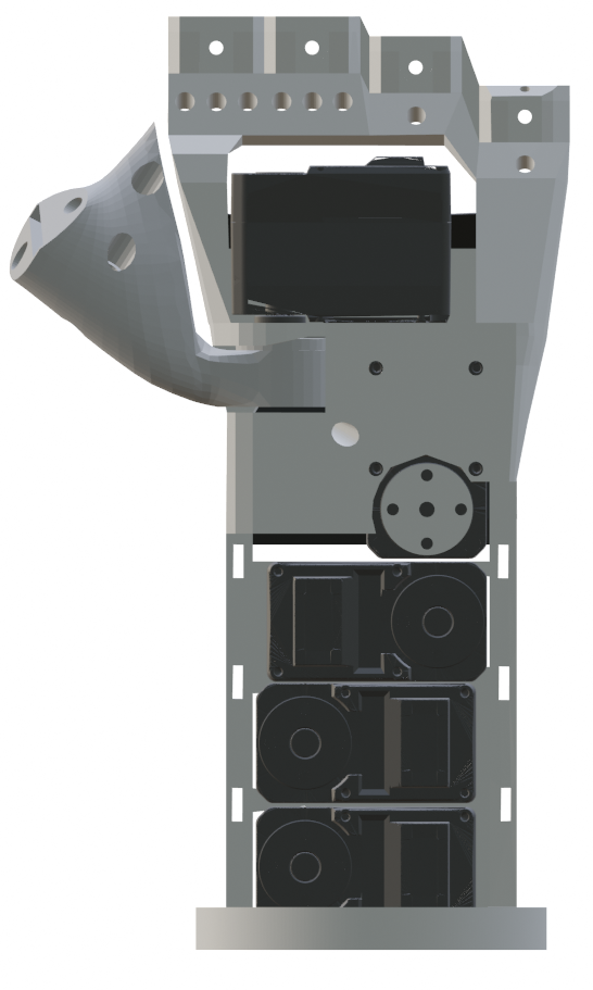
2Assembly : Servomotors Installation
Note: each servomotors must be secured in its slot using 4 screws M2, 8mm long. TBD
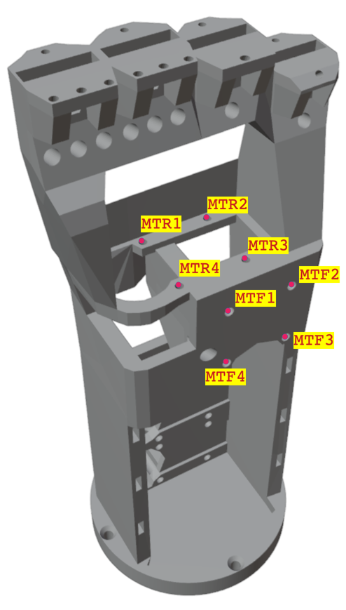
- Install the Thumb Rotation Servomotor in the SSTR slot (Holes:
MTR1, MTR, MTR3, MTR4)
◦ Note: Position the motor with the flange facing down.
Install the Thumb Flexion Servomotor in the SST slot (Holes: MTF1, MTF2, MTF3, MTF4)
◦ Note: Position the motor with the flange facing the front side of the skeleton.
Connect the servomotor in the SSTR slot to the one in the SST slot.
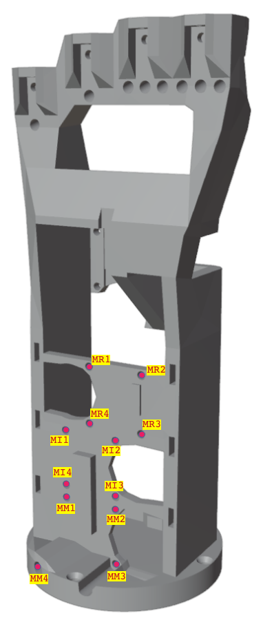
Install the Middle Flexion Servomotor in the SSM slot (Holes: MM1, MM2, MM3, MM4)
◦ Note: Position the motor with the flange facing the rear side of the skeleton.
Connect the servo motor in the SST slot. to the one in the SSM slot
Install the Ring Flexion Servomotor in the SSR slot (Holes: MR1, MR2, MR3, MR4)
◦ Note: Position the motor with the flange toward the rear side of the skeleton.
Connect the servomotor in the SSM slot to the one in the SSR slot
Install the Index Flexion Servomotor in the SSI slot (Holes: MI1, MI2, MI3, MI4)
◦ Note: Position the motor with the flange toward the rear side of the skeleton
Connect the servomotor in the SSR slot to the one in the SSI slot
- Install the Thumb Rotation Servomotor in the SSTR slot (Holes:
MTR1, MTR, MTR3, MTR4)
-
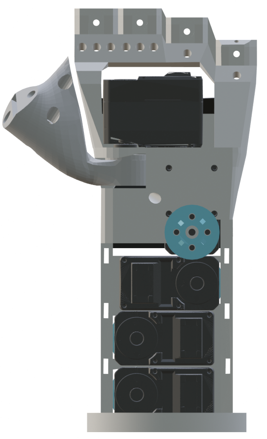
3Thumb Base Installation
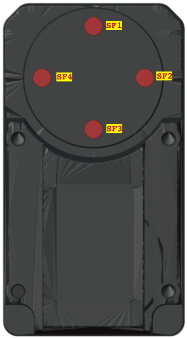
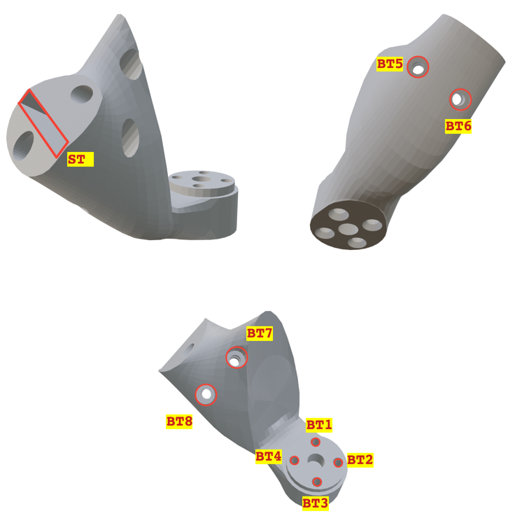
Thumb Base on Thumb Rotation servomotor flange (4 bolts M3, 10mm long) (Flange holes: SF1, SF2, SF3, SF4, Thumb Base holes: BT1, BT2, BT3, BT4)
-
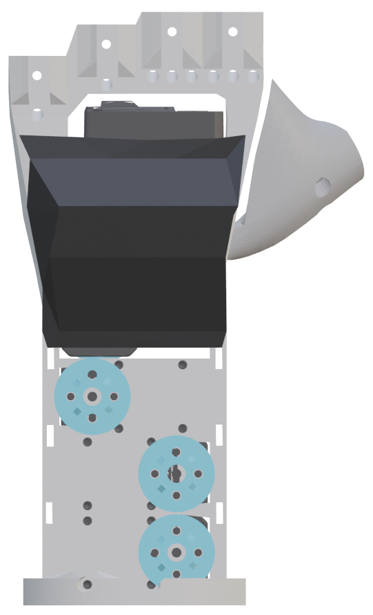
4Spools Installation
- Place a spool on the servomotor in the SST slot.
- Screw a spool with four hexagonal head bolts M3, 10mm long, (including a split washer).
- Place a spool on the servomotor in the SSR slot.
- Screw a spool with four hexagonal head bolts M3, 10mm long, (including a split washer).
- Place a winder on the servomotor in the SSI slot.
- Screw a spool with four hexagonal head bolts M3, 10mm long, (including a split washer).
- Place a winder on the servomotor in the SSM slot.
- Screw a spool with four hexagonal head bolts M3, 10mm long, (including a split washer).
TODO REPLACE PHOTO
-
5Upper Fingers Installation
Note: Each finger must be secured in its slot on the skeleton with a bolt M3 and long 10mm.
Insert the finger into the slot, then the bolt from behind, then the nut on the front of the skeleton and bolt it.
Assembly sequence:
- Index (slot: SI; holes: BI1, BI2)
- Middle (slot: SM; holes: BM1, BM2)
- Ring (slot: SR; holes: BR1, BR2)
- Little (slot: SL; holes: BL1, BL2)
-
6Thumb Installation
Note: The thumb must be secured in its ST slot on the thumb base with 2 bolts M3, long 15mm. TBD: ADD STEP FOR THE BASE CONNECTOR
Insert the thumb into the slot, then the 2 bolts from behind (holes BT5, BT6), then the nuts from the other side (holes: BT7, BT8), and bolt it.
-
7Tendons Installation : Preliminary Information
Safety Informations
!! DO NOT PULL TENDONS WITH BARE HANDS!!
MANDATORY
- Use the vise to hold still the part to be worked on
- Use the pliers to pull the tendons
POSSIBLE INJURIES:
- Severe cuts to fingers
- Severe bleeding
MANDATORY TO USE THE VISE
MANDATORY TO USE THE PLIERS
DANGER OF CUTTING FINGERS BY NYLON CABLES
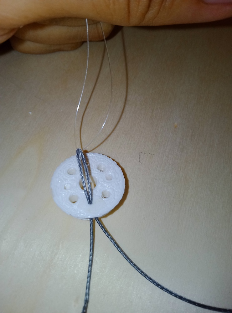
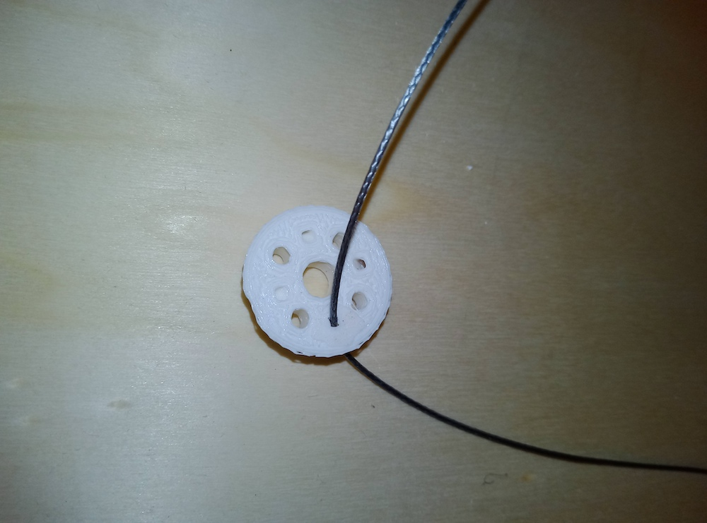
Usage of the Nylon Needle
Tendons are thin and difficult to thread, so a special needle is needed. This special needle is actually a nylon thread used as a needle. This method was chosen after multiple attempts, using various tools, as it proved to be the fastest, most reliable, and safest.
The following shows the procedure for threading the tendon through a hole using a nylon thread
(10cm, 0.35mm diameter) as a needle:
NOTE: From now on, we will simply refer to this sequence of operations as "Threading the
Tendon". It is implicitly assumed that this is done using the nylon needle.
-
8Tendons Installation for Index or Middle Finger
ATTENTION: Tendons can cause severe cuts to fingers!
MANDATORY: Use the vise to hold still the skeleton and the pliers to pull the tendon.
TODO
-
9Nomenclature of parts
Nomenclature of thumb servomotors holes
![]()
Nomenclature of upper fingers servomotors holes
![]()
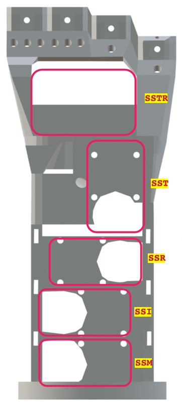
Nomenclature of servomotor slots![]()
Nomenclature of servomotor flange holes
![]()
Nomenclature of Tendons Pipes
TODO TODO TODO TODO TODO TODO
Nomenclature of upper fingers slot and holes
![]()
Nomenclature of Thumb base slot and holes
![]()
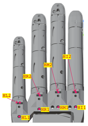
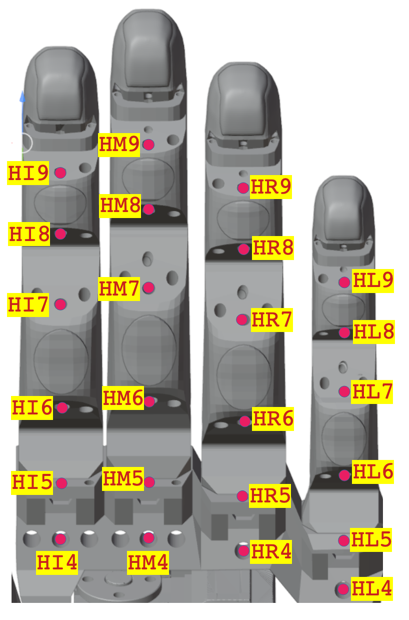
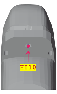
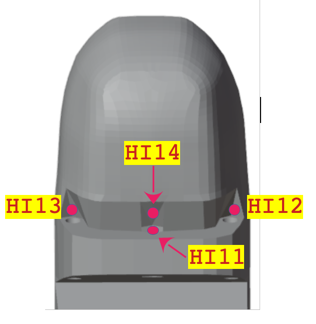
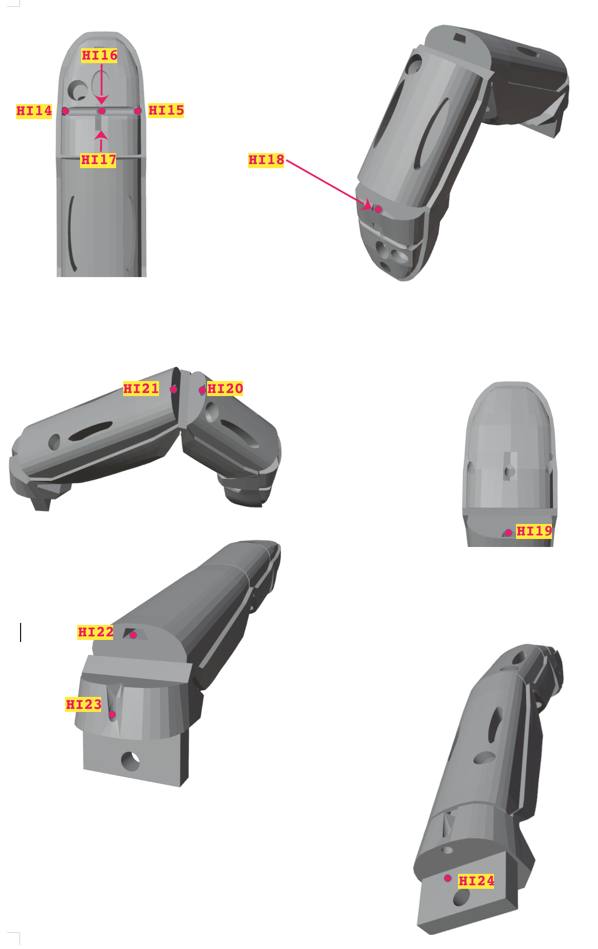
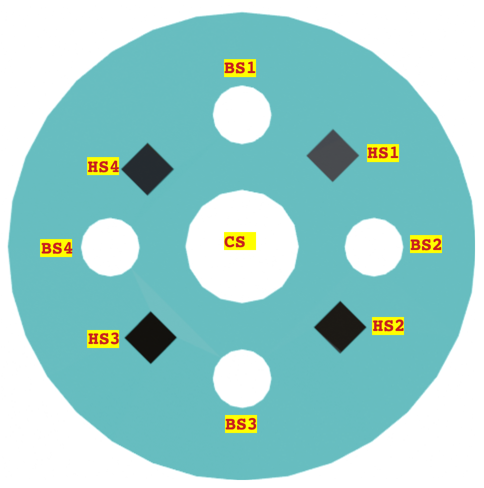
Nomenclature of tendon holes
![]()
![]()
![]()
![]()
![]()
Only the names of the holes for the index finger are shown. The names of the other finger holes can be obtained by replacing the prefix HI with the name of the desired finger. Below are the prefixes for the names of the other upper fingers (middle, ring, and little fingers).- Middle: HM
- Ring: HR
- Little: HL
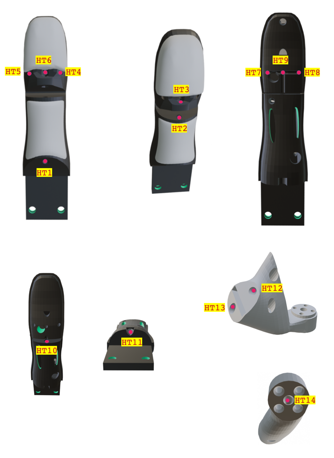
Nomenclature of thumb tendon holes
![]()
Nomenclature of spools holes
![]()
Nomenclature of hand palm holes
TODO TODO TODO TODO TODO
Nomenclature of covers
TODO TODO TODO TODO TODO
Nomenclature of electronic board holes
TODO TODO TODO TODO TODO
-
10[ADVANCED] Creating Silicone Pads for Robotic Fingers
This section is for builders who 3D print their own fingers.
Pre-assembled kits include finished fingers with silicone pads already installed.
This guide covers the complete process of adding soft, grippy silicone pads to 3D-printed robotic fingers using injection molding.Safety

READ THE SILICONE INSTRUCTIONS MANUAL! 
HARMFUL SUBSTANCES 
ENSURE PROPER AIR VENTILATION 
WEAR PROTECTIVE MASK 
WEAR PROTECTIVE VINYL GLOVES 📹 Process Overview
Video 1: Silicone Preparation
Watch the mixing and degassing process.
Video 2: Injection into Finger
See the injection technique into the clamped finger mold.
Video 3: Demolding & Cleanup
Removing the finger from the cast and finishing.
🛠️ Materials & Tools
3D Printed Parts- Finger: Dual-material print (PLA + TPU) from IDEX printer
- Cast/Clamp: 3D-printed in PLA
Consumables
- Large paper sheet to protect desk
- Paper sheets to clean silicone from bottles, parts and tools
- Skin-Safe Silicone (alternative choices):
- Smooth-On Dragon Skin 10NV
- Reschimica R PRO GLASS- Mixing Cups & Sticks (If reusable they must be washed with acetone and soap and water after use, see the cleaning chapter at the end)
- Isopropyl Alcohol (for cleanup)
- Pure Acetone (for cleanup)
Equipment
- PROPER AIR VENTILATION- FP2 PROTECTIVE MASK
- VINYL GLOVES (OTHER GLOVES COMPROMISE SILICONE PROCESS)
- PLASTIC CLAMPS
- PLASTIC LATEX FREE SYRINGE
📝 Step-by-Step Instructions
1. Prepare the Finger & Mold
Ensure the dual-printed finger (PLA/TPU) is clean and dry.
Insert the finger into the cast and clamp it securely.
2. Mix & Degas the Silicone
Measure silicone parts A and B at the recommended ratio (1:1 by volume).
Mix thoroughly until the color is uniform.
Pour into a clean disposable cup from 20cm height to make the liquid thin and remove bubbles
3. Inject Silicone (proximal phalange first, then medial, then distal)
Draw the mixed silicone into a syringe, slowly to prevent air from entering
Keep the finger upright, at leasts by 45 degrees, to allow liquid siliconte to fill all cavities
Slowly inject silicone into the lower injection hole until it comes out from the upper ejection hole
Tap the mold gently to encourage air escape.
4. Cure
Let the silicone cure at room temperature for 24 hours (follow manufacturer's specs).
5. Demold
Remove clamps and carefully (slowly) separate the cast from the finger.
Peel away any silicone flash or overflow manually.
Use a cutter or your fingers to remove residues from the finger surfaces.
Dispose consumables.
6. CLEANING
All surfaces contaminated by silicone must be cleaned !
If you used reusable cups, wait silicone cures, then remove and clean as explained below.
Cleaning process:
- put acetone on a paper or fabric towel and clean the part/tool which needs cleaning with it, until all residue of silicone are removed
- put alcohool on a paper or fabric towel and clean the part/tool which needs cleaning with it
- wash with hot water and soap thoroughly in a sink
- rewash with hot water without soap to remove any soap residue
- let it dry
- at the end, dispose in a bag all consumables, including the towel used
💡 Tips & Troubleshooting
Bubbles in pads? A little bit is ok, bu if they are too many: ensure adequate degassing and slow injection.
Silicone sticks to mold? Just pull it slowly. You may need to remove excess silicone comed out from sides before separating the cast form the finger.
Incomplete fill? Ensure finger is upright during injection, inject more slowly.
🔗 Related Resources are in the files section.
Dual-material (PLA/TPU) finger design files
Cast/clamp STL files
📌 Summary
This method produces durable, compliant silicone pads that enhance grip and protect objects during manipulation. The dual-material finger provides rigid structure with flexible joints, while the injected silicone adds soft, high-friction contact surfaces.
Have questions or improvements? Share your results in the comments!
Yeah Robotic Hand (formerly Rebelia)
A low cost robotic hand for robots and humans


Discussions
Become a Hackaday.io Member
Create an account to leave a comment. Already have an account? Log In.