Close
0%
0%

PD240W

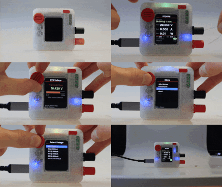
Pocket-sized 240W lab supply! Leverages USB-PD 3.2 EPR for adjustable 48V/5A output.

Similar projects worth following
An open-source, programmable USB-C Power Delivery supply based on the RP2040. Supports PD 3.2 EPR (up to 48V/5A), features a color IPS display with current limiting, and includes specialized safety features for motor drive testing.

Firmware & Hardware - GitHub

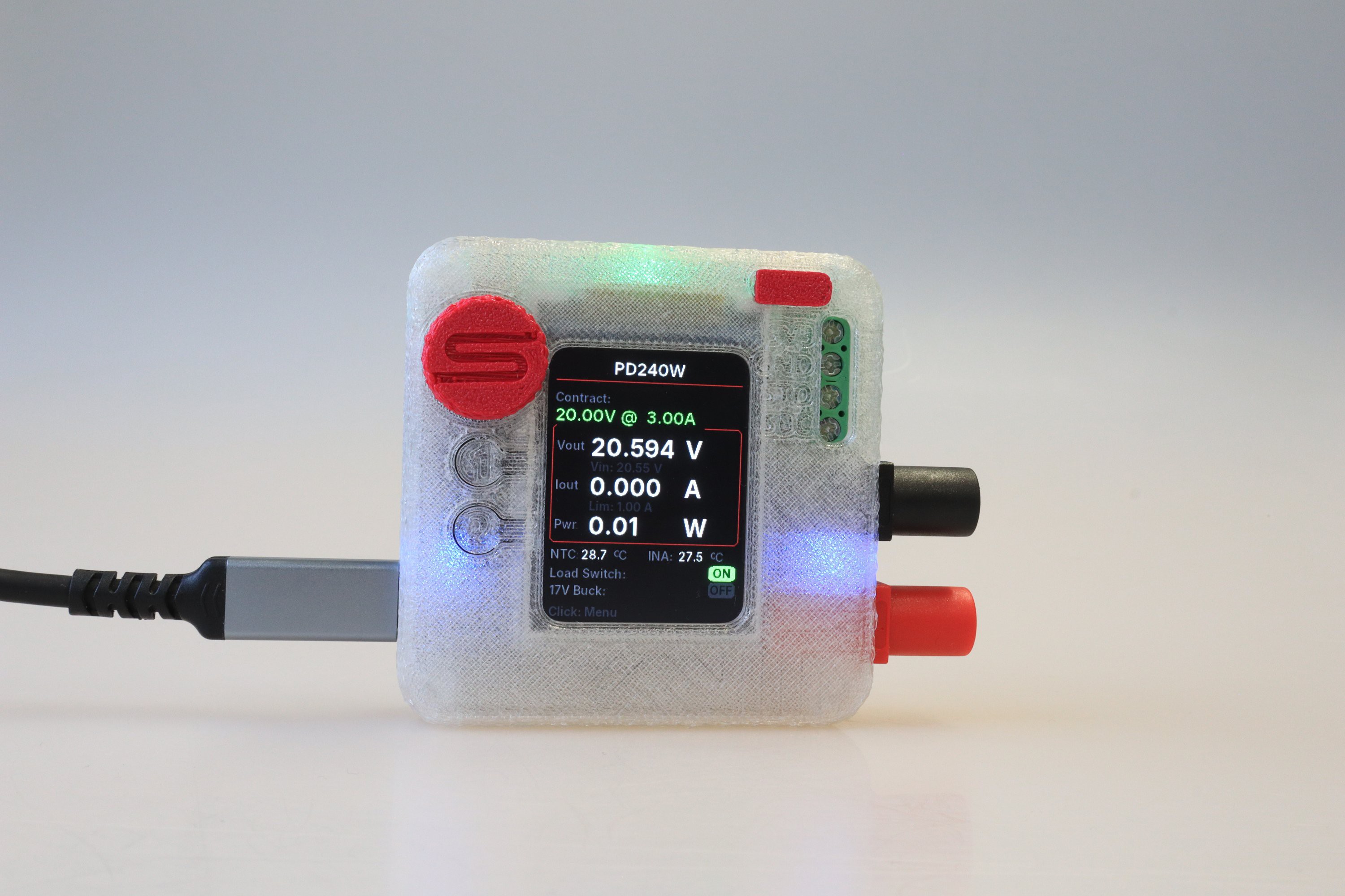
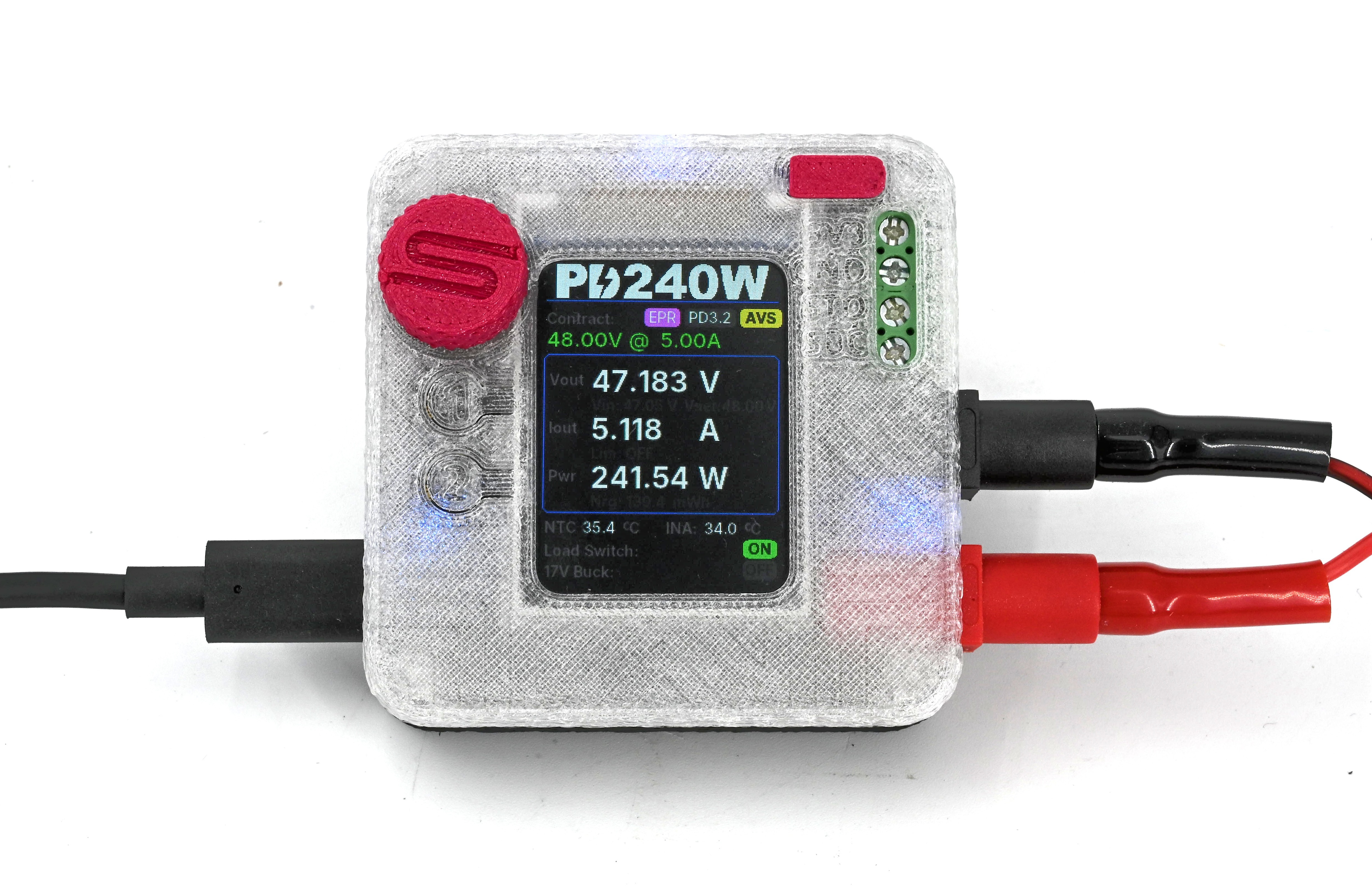
PD240W is an open-source, adjustable power supply designed to leverage the modern capabilities of USB-C Power Delivery (PD 3.2). While it fits in the palm of your hand, it is capable of negotiating up to 48V at 5A (240W), effectively turning high-power GaN chargers into fully programmable laboratory bench power supplies.

Built around the Raspberry Pi Pico (RP2040), this device bridges the gap between smart USB chargers and raw DC power requirements. While originally designed for testing motor drives in the field, it serves as an excellent general-purpose portable lab supply.
Key Features: 

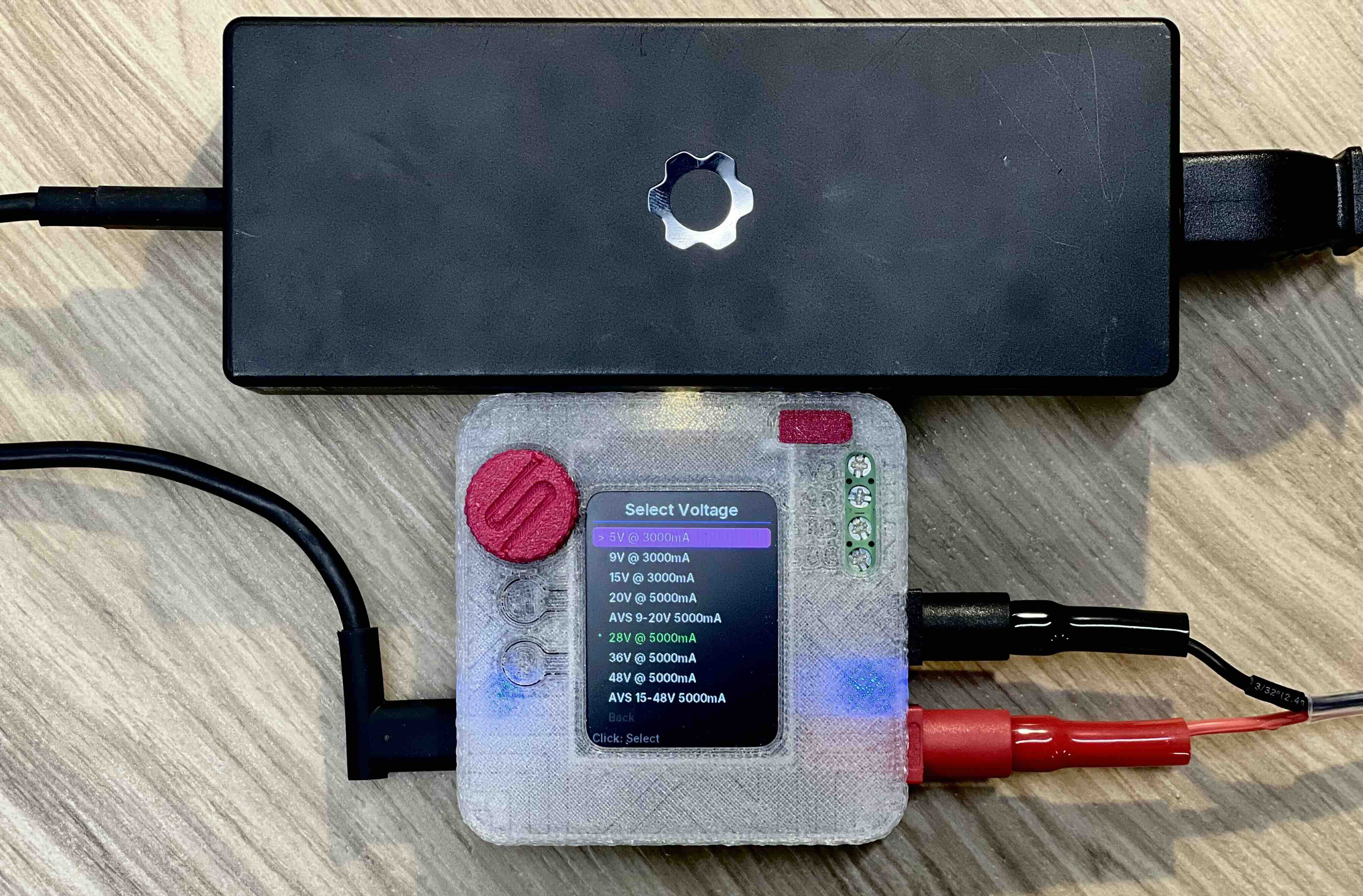
  • High Power Capability: Supports the Power Delivery standard up to 3.2 with EPR (Extended Power Range), allowing negotiation of Fixed, PPS (Programmable Power Supply), and AVS (Adjustable Voltage Supply) profiles up to 48V. 
  • Precision Control: Adjustable current limiting (10mA - 5A) with software-based constant-current (CC) regulation, and fine voltage tuning via a rotary encoder. A closed-loop tuner trims PPS and AVS requests to compensate for cable drop and charger inaccuracy. 
  • Rich UI: Features a 240x320 IPS display with anti-aliased fonts, providing real-time feedback on voltage, current, power, and thermal status. 
  • Safety First: Includes hardware overcurrent protection, overtemperature monitoring (NTC + internal sensors), and interrupt-based safety cutoffs. 
  • Motor Drive Specialized: Features a dedicated 17V Buck Output to simulate STO/SBC (Safe Torque Off) voltages for motor controller testing.

Hardware Overview
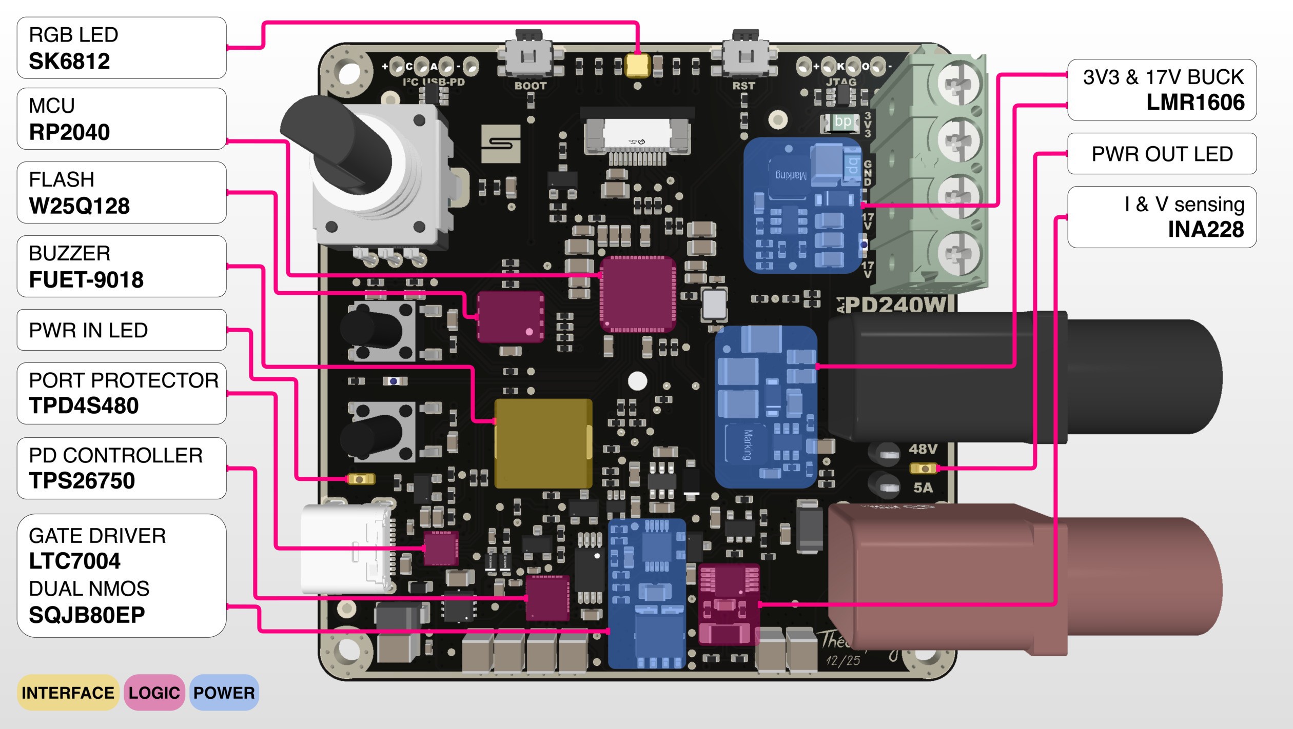
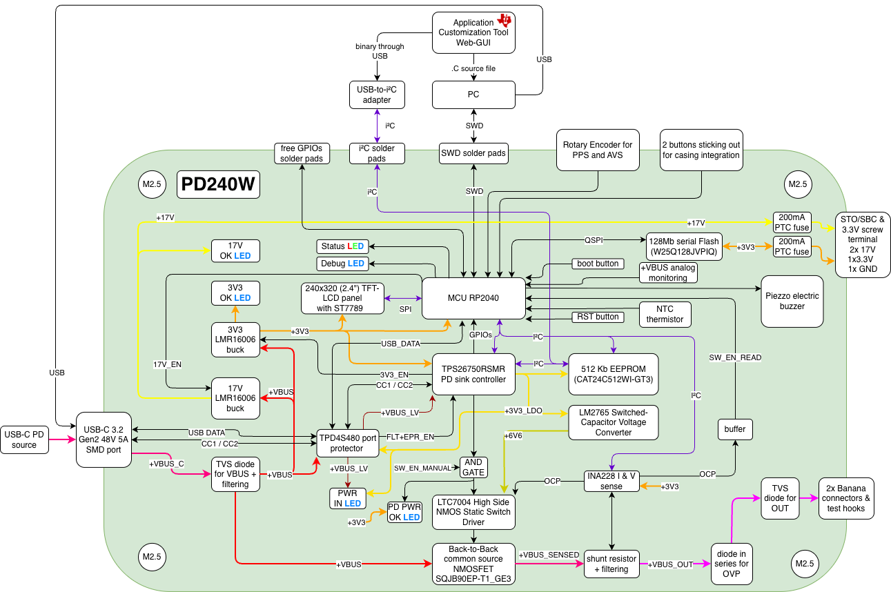
The core power negotiation is managed by the TI TPS26750 USB PD controller. It communicates with the USB-C source to establish contracts. The controller's configuration is loaded from a dedicated CAT24C512 EEPROM. The main power path from the USB-C connector to the output banana jacks is switched by back-to-back NMOSFETs, driven by an LTC7004 high-side driver. For safety, this driver is enabled via an AND gate, requiring both a control signal from the RP2040 and a no-fault status from the TPD4S480 input protector. Voltage and current at the output are precisely monitored by a TI INA228, which also provides a fast, hardware-based overcurrent protection (OCP) signal. The board generates necessary internal power rails from the main VBUS input using two LMR16006 buck converters:

  • 3.3V Rail: Powers the RP2040, display, and logic circuits.
  • 17V Rail: Provides the STO/SBC voltage for motor drives. This output is actively enabled by the RP2040 only when the VBUS voltage is sufficient.
PCB Specifications 

  • Single-side assembly, 211 components
  • Dimensions: 66mm x 66mm 
  • Stackup: 6 Layers (Sig/PWR - GND - PWR - Sig - GND - Sig/PWR) 
  • Finish: ENIG with Black Solder Mask Complexity: 215 components 
  • Cost: Approximately $85 per assembled product (at low volume)

Firmware & Software

The firmware is written with around 20k lines of C++17 using the Pico SDK 2.2.0. It utilizes a custom non-blocking event loop architecture to handle the UI, PD negotiation, and safety checks simultaneously.

Notable Software Features: 

  • Auto PPS Tuning: A closed-loop control system that actively measures the output voltage and adjusts the PPS request to compensate for cable drop and charger inaccuracies.
  • Constant-Current Control: Software-based CC regulation that adjusts the negotiated voltage to hold a target current.
    Safe EPR Exit: A multi-step step-down sequence that walks the voltage out of the Extended Power Range before dropping to 5V, avoiding charger resets.
  • Serial CLI: A USB serial command interface for remote inspection, scripting, and control.
    Charger Diagnostics: An on-device screen that reports the source's advertised capabilities and detected PD revision (PD3.0 / 3.1 / 3.2).
  • Persistent Settings: User preferences (brightness, sounds, default limits) are stored in flash with CRC32 validation. ...
Read more »

  • FW 2.0.0: 48V@5A is here!

    Theo Heng06/16/2026 at 15:21 0 comments

    Remember that Framework 240W PD3.2 charger I ordered at the end of the last log? It showed up, and I finally got to push PD240W to the power it was named after. Firmware 2.0.0 is the result of evenings and evenings of software development and testing. USB-PD 3.1/3.2 is officially supported, and many new features have been added.

    The headline is full AVS and EPR negotiation, so the board now climbs to 48V instead of topping out in the SPR range. Getting there was quite a journey. When I received the Framework charger, I immediately plugged it in, with a mix of hope and excitement. To my surprise, on the first try, I got a 48V reading on my screen from the INA228, and I thought that this was victory, and that in 30mins I would be done with EPR contracts. Oh boy was I wrong. 

    The first half of 2.0.0 was about EPR, AVS, and USB-PD 3.2, and almost all of the pain lived in one place: getting out of an EPR contract. Climbing up to 48V is the easy direction; coming back down is where the problems start. The USB-PD spec says that when you leave the EPR range you have to step the voltage down to 5V within a tight time window. Request a big drop directly, say 48V straight to 5V, and a spec-compliant charger without active discharge will simply reset the port, and the board reboots.

    What worked is a three-step exit sequence. Instead of jumping straight to the target, I first use an EPR AVS APDO to slide the voltage down to the lowest voltage possible while still inside an EPR contract, then request 5V Fixed to cleanly exit EPR, and only then ask for the real SPR target. The catch is that this trick requires a source advertising an usable AVS APDO, and not every charger does.

    There's also a limit to how much the software can do about the timing. Meeting that step-down-to-5V deadline means actually pulling the bus voltage down fast, and from 48V that only happens quickly if something is sinking the rail, which you can't count on. My small bleed resistor wasn't enough. It was sized small on purpose to avoid wasting power. So for the next hardware iteration I'm thinking of adding an active discharge path: a switched load the firmware can fire to yank VBUS down on command, so the board can hit the deadline on its own instead of hoping the charger and the attached load cooperate.

    SPR AVS was the other rabbit hole, and the one that hurt the most relative to how small the fix turned out to be. SPR AVS is brand new in USB-PD 3.2, and just discovering it in the source's advertised PDOs was quite a challenge. SPR AVS nominally covers 9–20V, but on my hardware I can only reliably land it between 15 and 20V. Request anything below 15V and the contract collapses back to a 9V fixed rail. My current suspicion is the TPS26750 itself: the silicon was designed before PD3.2, and its AVS-enable bit is really the EPR AVS-enable bit, which the controller enforces down to a hard 15V floor, so sub-15V requests fall back to 9V.

    Apart from that, the software-based constant-current control is essentially finished now: it closes the loop by measuring real output on the INA228 and adjusting the negotiated voltage to hold the current you asked for. That meant forcing the AVS/PPS auto-tuner to step aside while CC is regulating, so the two loops don't fight over the same voltage. Two more bugs came out of reboots: a voltage spike at startup in "last voltage used" mode, fixed by priming a safe contract before the boot screen even draws and clamping to 5V until PDO discovery can restore the real target, and a smarter startup restore so the board comes back into the right state after a reboot or a charger swap. On top of that there's a new basic charger diagnostics screen and a USB serial CLI for remote inspection and scripting, plus a UI pass, PD240W branding, clearer About screens, auto-dim, smoother visuals, and a long tail of bug fixes (badge/cursor restore, noisy logs, menu edge cases, and a lot of AVS/EPR negotiation regressions)....

    Read more »

  • KiCad port complete!

    Theo Heng03/16/2026 at 01:07 0 comments

    Porting the PD240W PCB from Altium to KiCad wasn't easy and took a solid 20+ hours to complete. KiCad handles project imports from Altium surprisingly well if you just want to navigate the schematic and inspect the layout or 3D model. However, making your project compile without errors, pass CI/CD tests, and making it fully compliant with your workflow and templates is quite a process.

    At the start, I had 999+ errors and 999+ warnings in both ERC and DRC. The most annoying part was syncing the symbols to their footprints without having to manually move a single footprint. I could also mention the grid differences in symbols, awkward placement of values and reference designators, font size mismatches, BOM cleanup, footprint type issues, fabrication layer mismatches, copper pours not having assigned nets, completely absent design rules, and missing layers...

    Anyway, it is all done now, and as promised, the schematic for revision V1.0.0 has been pushed to GitHub. I just ordered a Framework 240W PD3.2 charger that should arrive in a week. I will finally be able to push this project to the limits for which it was conceived. Firmware updates will follow. Stay tuned!

View all 2 project logs

Enjoy this project?

Share

Discussions

Theo Heng wrote 03/16/2026 at 03:46 point

@Rene @ninjaWw PCB files and schematic are now on GitHub

  Are you sure? yes | no

Rene wrote 03/06/2026 at 18:56 point

This is very cool! I've been thinking about this for a good while myself!
Would it be difficult to upgrade this to four-probe? I see the INA has a separate VBUS pin, so with a jumper it should be easy to get a three probe, but I'm not sure about GND, because it doesn't have a separate AGND. Especially for battery charging that'd be super cool.
BTW, is there a reason for not sharing the circuit diagram explicitly?

  Are you sure? yes | no

Theo Heng wrote 03/06/2026 at 21:05 point

Hello Rene, thank you for the comment. 

I'm not sure what you mean with probe. Do you mean adding a second channel for which you could monitor voltage? About charging multi-cells batteries, yes it would be nice, but it defeats a bit the purpose of a general-purpose power supply. However you can reprogram the TPS26750 or code your own script to negotiate charging profiles if you want to charge a single cell battery. 

And for the schematics, it is as I said in my other comment, currently I cannot share it, but I will in a couple of weeks.

  Are you sure? yes | no

Rene wrote 03/07/2026 at 07:37 point

Adding a specific program to the MCU was exactly the idea (for batteries), keeping it ALSO a universal PSU. However, four-probe/-wire/-terminal measurement is something that a lot of fancy (general purpose) PSU's implement: https://www.tmatlantic.com/encyclopedia/index.php?ELEMENT_ID=22008
The idea is to (optionally, can be bypassed with jumpers/switches) use separate wires for voltage measurement than for the current path. It allows you to neglect any voltage drop over the cables being used and instead control the voltage actually at the Device Under Test.

  Are you sure? yes | no

ninjaWw wrote 03/04/2026 at 07:35 point

Thanks for the project being open source. However, the rotation angles of components Q1, J3, and J4 in the pick_and_place.csv document do not match those in the PCB layout. Also, the screw-type terminal blocks are not shown in the BOM.csv document. It would be even better if the schematic diagram could be open sourced.

  Are you sure? yes | no

Theo Heng wrote 03/04/2026 at 14:41 point

Hey, thanks for the feedback!

About the rotation angles idk what happened, but it is not a big issue since most of component need to be manually rotated anyway when ordering the assembled PCBs. I don't have time to fix this. 
About the screw terminals (and a few other components), this is because I ordered the PCBs without, and soldered them myself from stuff I had already at hand. I don't have time to fix this. 
For the schematic, I cannot share them at the moment because they are on Synapticon template on a non-open-source CAD tool. I'm working on a slightly simplified version of the project, which is ported on KiCad. Once I'm ready, I will make it fully open source ;-)

  Are you sure? yes | no

Similar Projects

Does this project spark your interest?

Become a member to follow this project and never miss any updates