 Theo Heng

Firmware & Hardware - GitHub
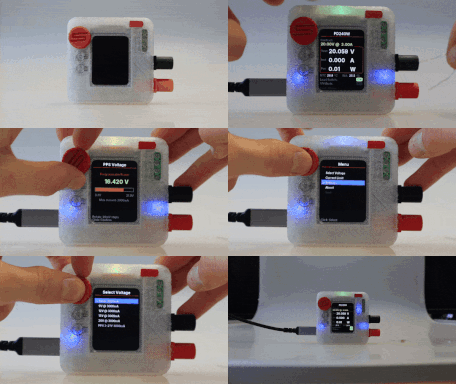
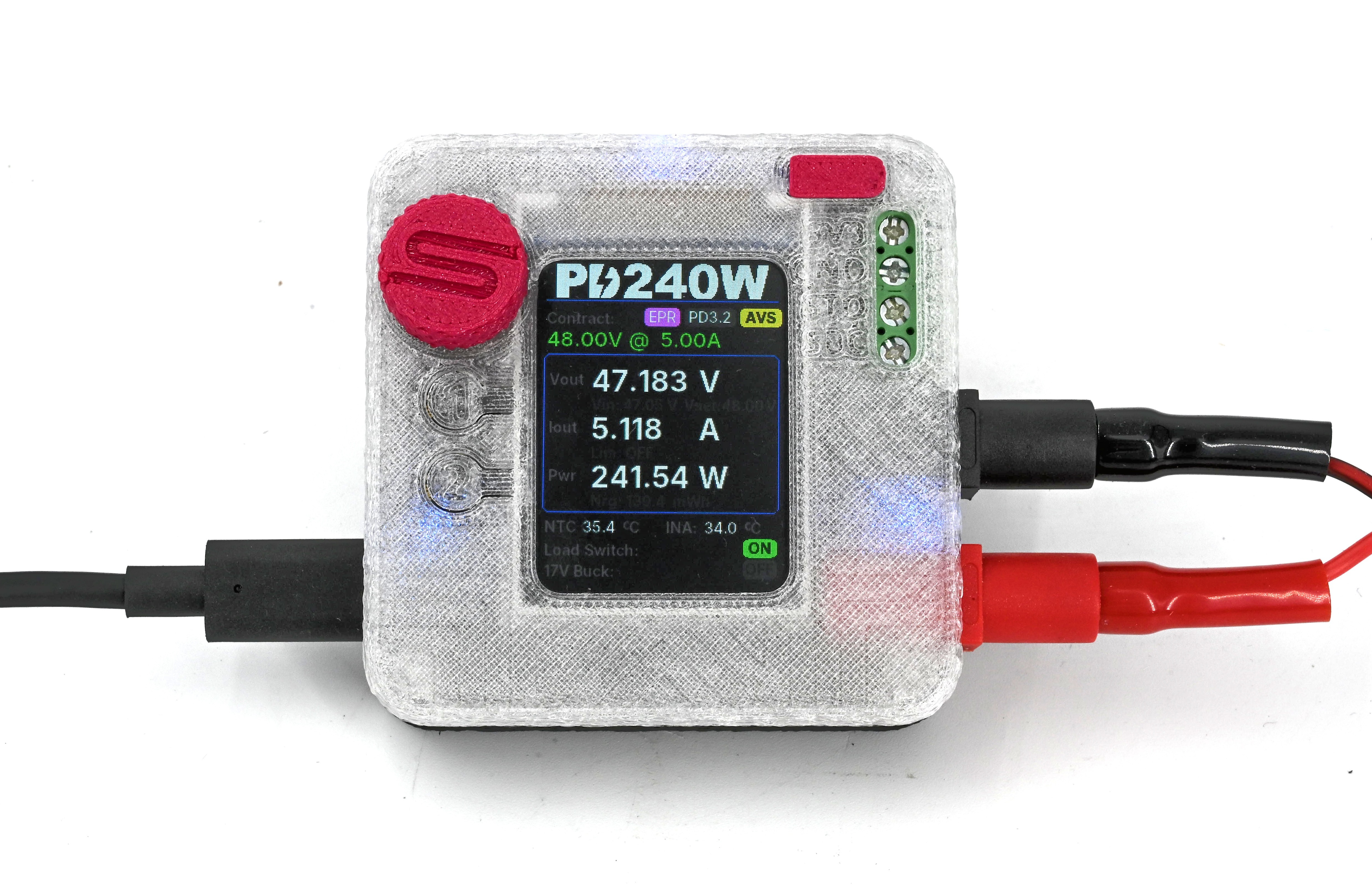
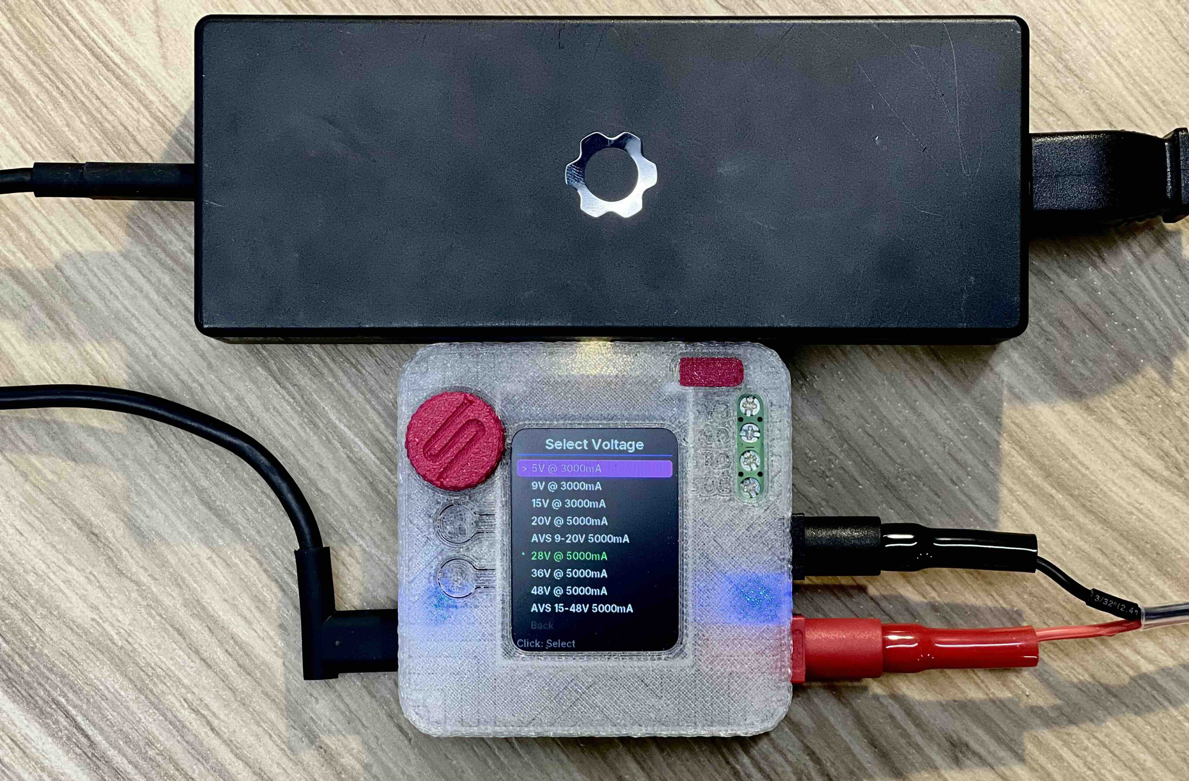
PD240W is an open-source, adjustable power supply designed to leverage the modern capabilities of USB-C Power Delivery (PD 3.2). While it fits in the palm of your hand, it is capable of negotiating up to 48V at 5A (240W), effectively turning high-power GaN chargers into fully programmable laboratory bench power supplies.
Built around the Raspberry Pi Pico (RP2040), this device bridges the gap between smart USB chargers and raw DC power requirements. While originally designed for testing motor drives in the field, it serves as an excellent general-purpose portable lab supply.
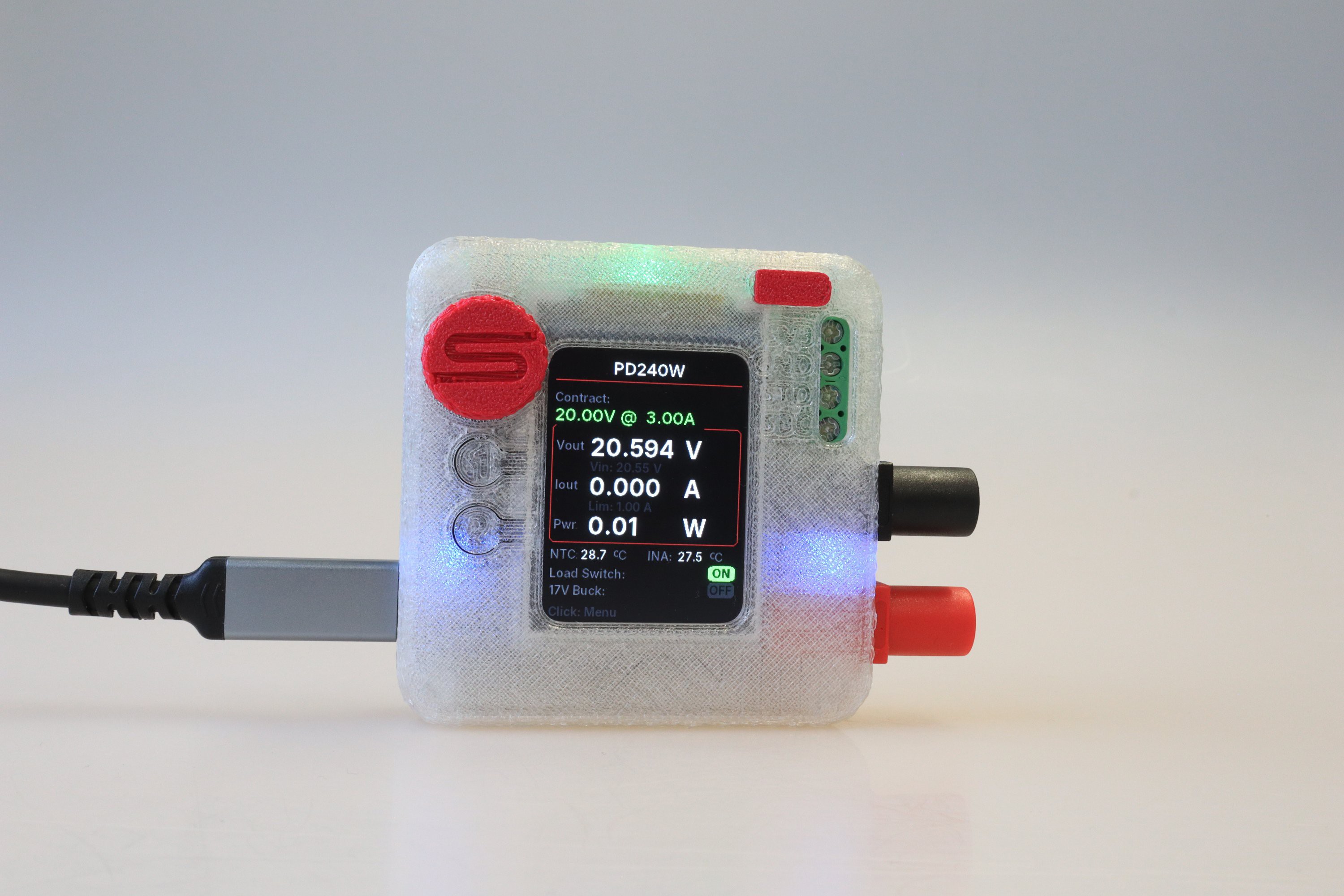
Key Features:
- High Power Capability: Supports the Power Delivery standard up to 3.2 with EPR (Extended Power Range), allowing negotiation of Fixed, PPS (Programmable Power Supply), and AVS (Adjustable Voltage Supply) profiles up to 48V.
- Precision Control: Adjustable current limiting (10mA - 5A) with software-based constant-current (CC) regulation, and fine voltage tuning via a rotary encoder. A closed-loop tuner trims PPS and AVS requests to compensate for cable drop and charger inaccuracy.
- Rich UI: Features a 240x320 IPS display with anti-aliased fonts, providing real-time feedback on voltage, current, power, and thermal status.
- Safety First: Includes hardware overcurrent protection, overtemperature monitoring (NTC + internal sensors), and interrupt-based safety cutoffs.
- Motor Drive Specialized: Features a dedicated 17V Buck Output to simulate STO/SBC (Safe Torque Off) voltages for motor controller testing.
Hardware Overview
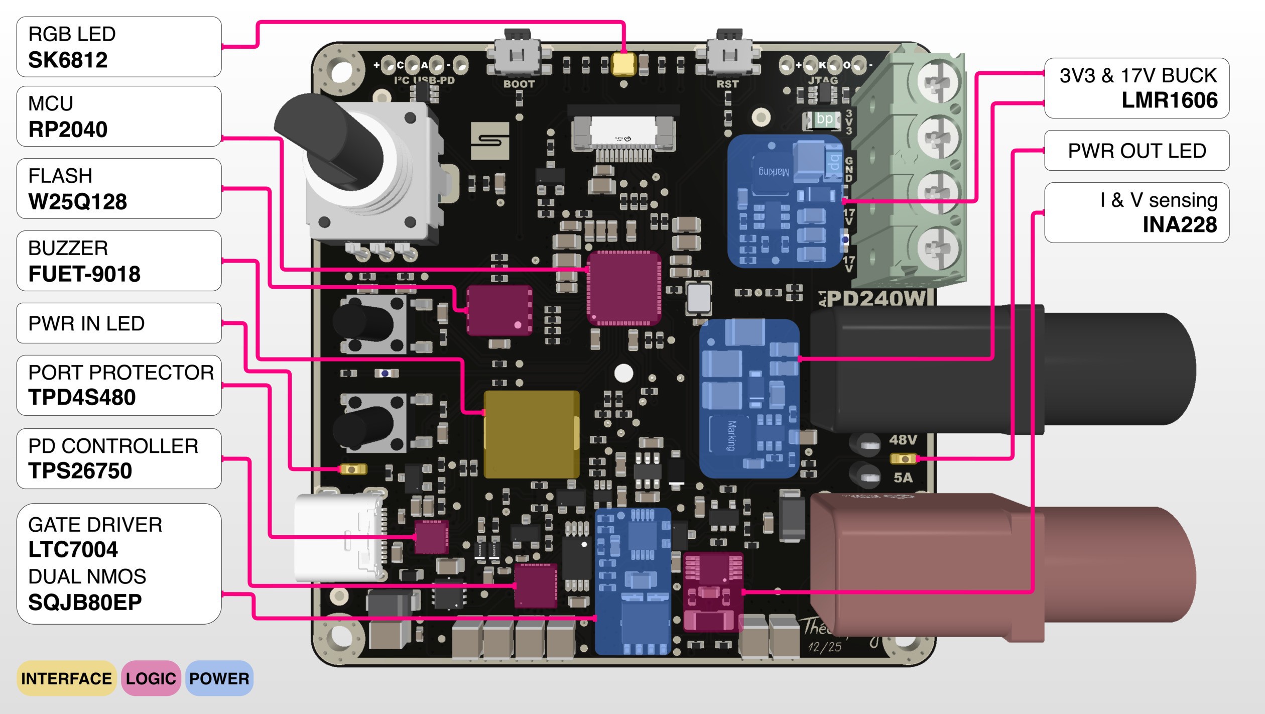
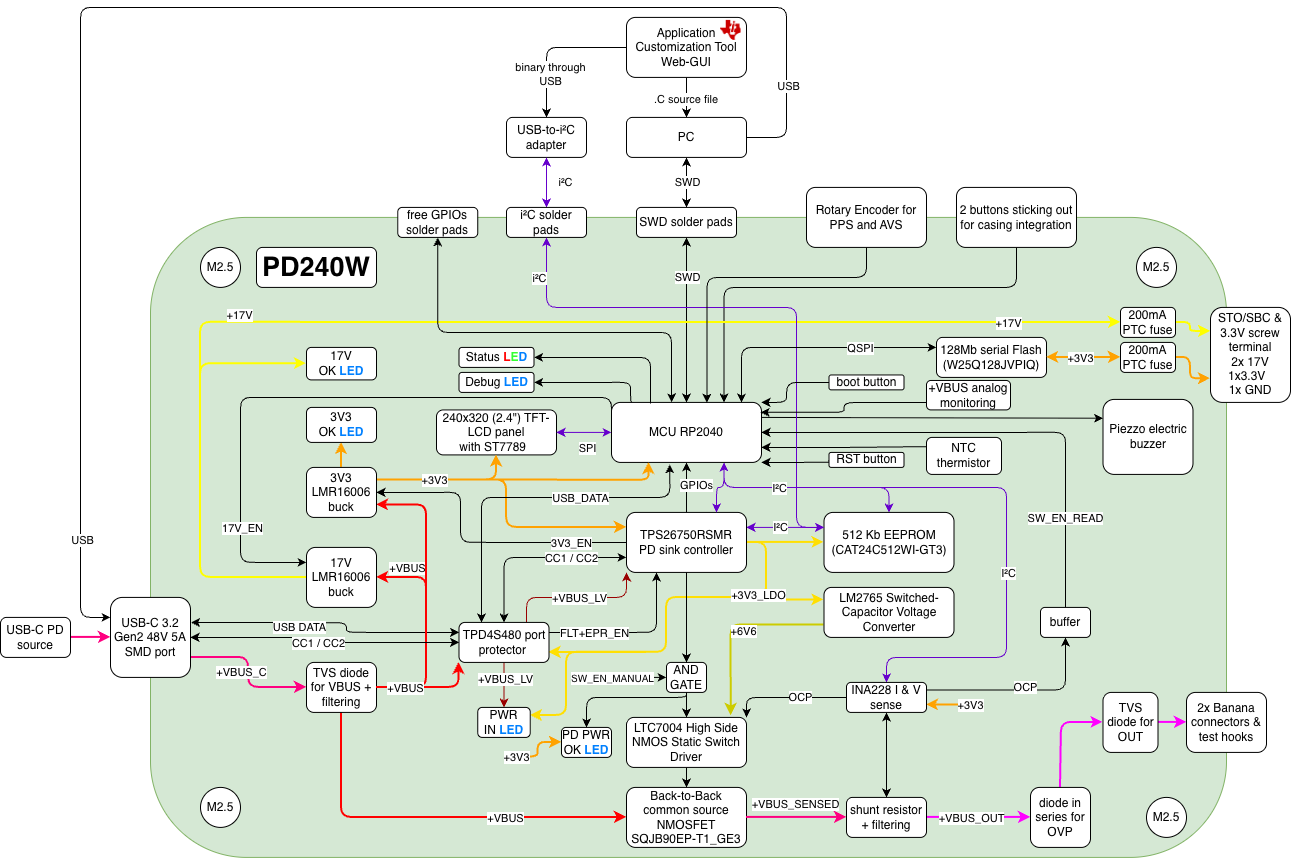
The core power negotiation is managed by the TI TPS26750 USB PD controller. It communicates with the USB-C source to establish contracts. The controller's configuration is loaded from a dedicated CAT24C512 EEPROM. The main power path from the USB-C connector to the output banana jacks is switched by back-to-back NMOSFETs, driven by an LTC7004 high-side driver. For safety, this driver is enabled via an AND gate, requiring both a control signal from the RP2040 and a no-fault status from the TPD4S480 input protector. Voltage and current at the output are precisely monitored by a TI INA228, which also provides a fast, hardware-based overcurrent protection (OCP) signal. The board generates necessary internal power rails from the main VBUS input using two LMR16006 buck converters:
- 3.3V Rail: Powers the RP2040, display, and logic circuits.
- 17V Rail: Provides the STO/SBC voltage for motor drives. This output is actively enabled by the RP2040 only when the VBUS voltage is sufficient.
PCB Specifications
- Single-side assembly, 211 components
- Dimensions: 66mm x 66mm
- Stackup: 6 Layers (Sig/PWR - GND - PWR - Sig - GND - Sig/PWR)
- Finish: ENIG with Black Solder Mask Complexity: 215 components
- Cost: Approximately $85 per assembled product (at low volume)
Firmware & Software
The firmware is written with around 20k lines of C++17 using the Pico SDK 2.2.0. It utilizes a custom non-blocking event loop architecture to handle the UI, PD negotiation, and safety checks simultaneously.
Notable Software Features:
- Auto PPS Tuning: A closed-loop control system that actively measures the output voltage and adjusts the PPS request to compensate for cable drop and charger inaccuracies.
- Constant-Current Control: Software-based CC regulation that adjusts the negotiated voltage to hold a target current.
Safe EPR Exit: A multi-step step-down sequence that walks the voltage out of the Extended Power Range before dropping to 5V, avoiding charger resets. - Serial CLI: A USB serial command interface for remote inspection, scripting, and control.
Charger Diagnostics: An on-device screen that reports the source's advertised capabilities and detected PD revision (PD3.0 / 3.1 / 3.2). - Persistent Settings: User preferences (brightness, sounds, default limits) are stored in flash with CRC32 validation. ...



 Daniel Knezevic
 Ludwin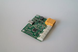
 Alex Klimaj
 Fridrik
@Rene @ninjaWw PCB files and schematic are now on GitHub