Allan Binder
-
On Vibe-coding Electronics
4 hours ago • 0 commentscontext: I'm building an e-ink smart clock, that uses 4x geiger counters to detect muons/high energy particles, and uses that to give users a cosmic oracle experience, and RNG based games/events. Press a button, ask a question, then a cosmic ray hitting the earths upper atmosphere answers.
3-4 million tokens before I ordered a single part
I have been toying around with this idea for a year or two (since watching Alpha-Phoenix's youtube video of the same idea) so I had a good idea of the shape and user experience that I was going for, but very little substance in terms of execution and design. I spent around two weeks and easily 2-3 million Opus 4.6 tokens, and >300k on GPT 5.4 reducing my uncertainty as much as possible. That phrasing is important because the model's were not in the designer seat; they would help me visualize and fill in understanding gaps far more than actually making architectural decisions. I'm sure they could have, but I wouldn't have been able to troubleshoot anything if it wasn't my own design. I think one thing people miss about AI workflows, when used properly, you learn exactly what you need to know, but not much else. If I were doing this 10 years ago I would have likely needed to learn 50-60% more information that was never used, because I didn't actually know what I needed to know. With the current generations of tools I was able to laser focus on information that was worth investing in, and basically nothing else. Take it or leave it, I'm sure some people will see that as passe, but experiencing it has been a breath of fresh air from my previous-overly-ambitious projects.
The result of this pre-planning phase was a fully designed and simulated breadboard, high confidence decision tree and a breadth of edge cases. One of my proudest accomplishments in this project so far is not hitting any roadblocks that required ordering a new part to continue working. I only have maybe 3 or 4 unused components, now that the breadboard prototype is proven. Anytime I hit a snag, I had the right capacitor or resistor or ferrite bead or whatever already to just keep moving forward. The entire build process was planned in isolated phases with concrete deliverables at the end of each phase, so if a new problem arrived, it would be clear what general area the source is from.Claude Code as a live lab notebook
During the entire breadboard phase I had a terminal window open with Claude Code running alongside the physical build. Every time I moved a jumper, measured a voltage, swapped a component, or observed a behavior change, I'd relay it to the session to be documented. This was incredibly valuable, and allowed me to run simulations when i wasn't with the device (remote Claude code sessions running simulations of my breadboard design to test a hypothesis while I'm out on a run is wild, taking a step back). Another advantage of documenting through Claude Code was allowing me to export the full breadboard schematic with descriptions of problems, then going to GPT 5.4/5.5 for a second opinion. This was fruitful every time I did it, and the two models work incredibly well together, more on this later though. Multiple times I would give Claude "jumper 56,g-46,a" and it would tell me that 46,a is already taken by something else, are you sure, and I would find I wired something wrong an hour ago, then correct it before needing to power on again.Quick model notes
This project started mid-way thought the Opus 4.6 /GPT 5.4 lifecycle, then as both rolled over to 4.7 and 5.5 I switched over to that (gradually for 4.7; I'll explain in a second). Opus 4.6 did 95% of the planning phase with GPT 5.4 for second opinions when it was clear I was hitting a knowledge gap in 4.6, or it was struggling with something that was clearly a limitation of the model. It's hard to describe what that constitutes, but if you've worked with these models extensively, you get a feel for different types of mistakes and uncertainties. For planning specifically, I much prefer Anthropic models if only for their tone. I am capable of doing the technical side of things, but if the model's tone doesn't align with me, or their output isn't structured how I like, it takes mental energy away from the task. This is my number one issue with OpenAI models; on a technical level I am absolutely certain I would have been fine with GPT 5.x alone, but the list of lists and bullet points style writing feels not-human. Also, to comment their tone or prose, Anthropic models actually feel like they are enjoying the project, they will show "excitement" when I come up with a novel solution, and get terse when I am getting distracted. I have found OpenAI models much more egalitarian and "I-am-a-tool-don't-pretend-I-am-human" which is probably healthier for my mental state, but I don't get the boost of focus or mental energy that comes along with the model telling me I'm the bestest boy for solving a problem it was struggling with.
During the introduction of 4.7 I am always wary about giving new models access to production code (sonnet 3.7 iykyk), especially because 4.7 has a massive prose change from 4.6, which on it's surface doesn't inspire confidence. I kept 4.6 active for two weeks or so, occasionally flipping over to 4.7 only to see the overly verbose prose and the "wait this isn't right" outside of thinking tokens (really, that should only ever be in thinking tokens. I suspect Anthropic's post training restricted it's thinking budget to save compute so that stuff just got moved to the output, but I digress). But after it passing tests and finding things 4.6 missed I switched over fully and it's actually been better than 4.6 on most technical dimensions. It can certainly trace a signal path better, but I've found it makes mistakes after 250k tokens (all models do), so I have an alert to remind me to compact or make a handoff doc if I hit that. I really can't tell the difference between GPT5.4 and 5.5, but I only used either of them for less than 10 prompts each. Always professional and very very knowledgable. OpenAI models feel like a contractor from a different firm is in the office for the day, whereas Anthropic models feel like an old coworker that doesn't like small talk.
Would I have done this without AI?Honestly probably not. In hindsight I very clearly had the skillset and capabilities, but passing the threshold of confidence to take this idea and turn it into a physical object, was probably too high for me to reach on my own. I don't really have anyone in my life that is capable of troubleshooting or spitballing technical solutions if something goes wrong. Two geiger tubes would have certainly been reachable with tutorials, but after seeing it's low detection rate, and deciding that was a poor user experience, I don't think I would have had confidence to pursue 4 tubes/six way coincidence gates. This is also not mentioning anything about programming the firmware for the ESP32 or the e-ink display, which again would have been doable, but taken weeks not minutes, for me to learn and execute.
Takeaway
Overall, amazing experience doing this AI assisted, Claude Code is an incredible tool. I understand a lot of people have mixed feelings about AI in general, but in my sample size of one, I am getting massive massive value from it on a daily basis, across disparate parts of my life. I would love to hear other people's thoughts. How are you using LLMs in a hardware setting? Do you think I actually did this myself or should I put an asterisks every time I say "I made this"? Anyway thank for reading o7. -
Six Channels of Muons Detected!!!
4 days ago • 0 commentsMuons detected
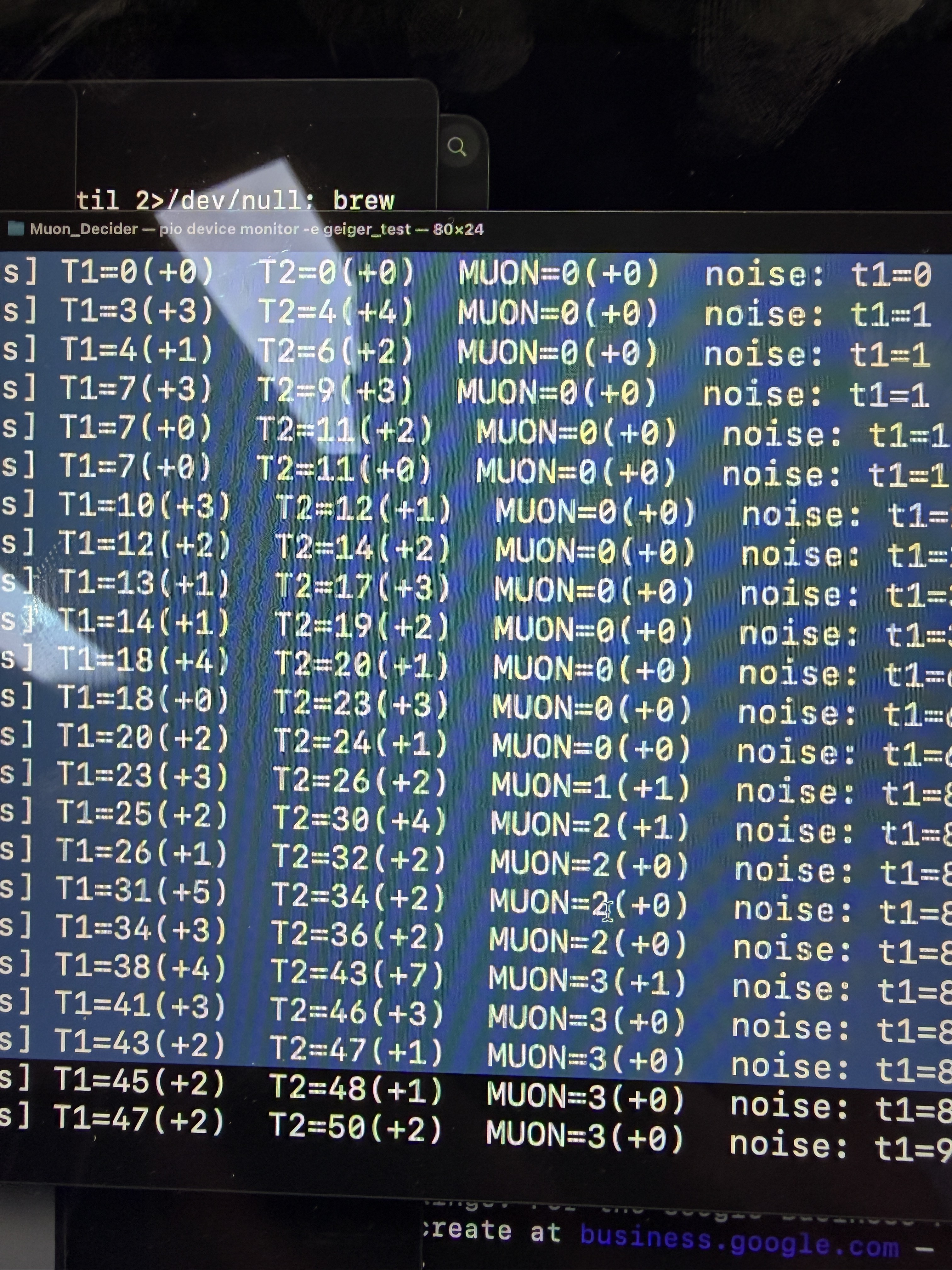
Picking up where the last post left off; I got the two-tube coincidence detection working. After reworking the pulse stretcher timing and tuning the AND gate window, the coincidence output started firing at a rate that made sense for sea-level muons. Not zero, not 100/minute, but exactly what the documentation suggests, 3-5 for a vertical tube pair.
That was a good day,
![]()
Then I tore it all downThe original design called for two tubes, but I have decided to move to four tubes (six pairs) for a few reasons. First, the main oracle experience, of press a button and wait, is magical if it's 10 seconds. If it's 30 seconds it stops being fun and exciting. Doubling the amount of tubes (and tripling channels) will massively increase the detection rate. At two tubes, the 90% wait could be as long as a minute, but with four tubes and six channels 90% wait is under 30 seconds, and average wait is under ten, which is a much better user experience.
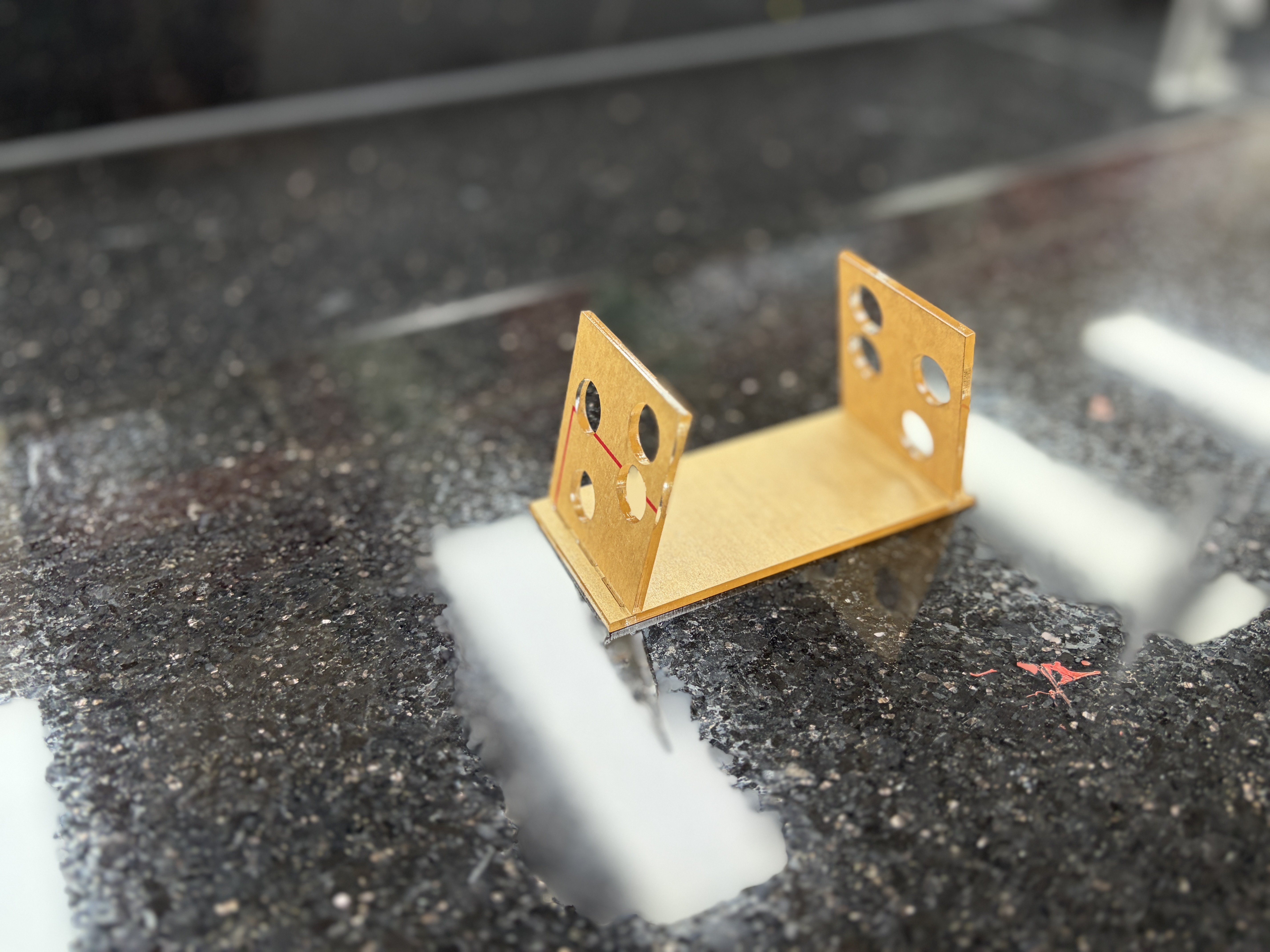
One other advantage of four tubes, is the ability to have a unique angle for each pair, which turn into natural rarity tiers, because a vast majority of muons are traveling vertically, and the more extreme angle the more rare of an event it is. This combined with the pressure/temp/humidity readings gives a multi-dimensional space of event combinations that can be used to trigger experiences on the clock face. Think rare enemies in a tower defense game, or unique farm visitors.I laser-cut an acrylic scaffold that holds all four tubes with each pair relationship fixed and repeatable. The soak test data from this rig will give me baseline coincidence rates for every angle, which feeds directly into how the rarity tiers get calibrated in firmware.
![]()
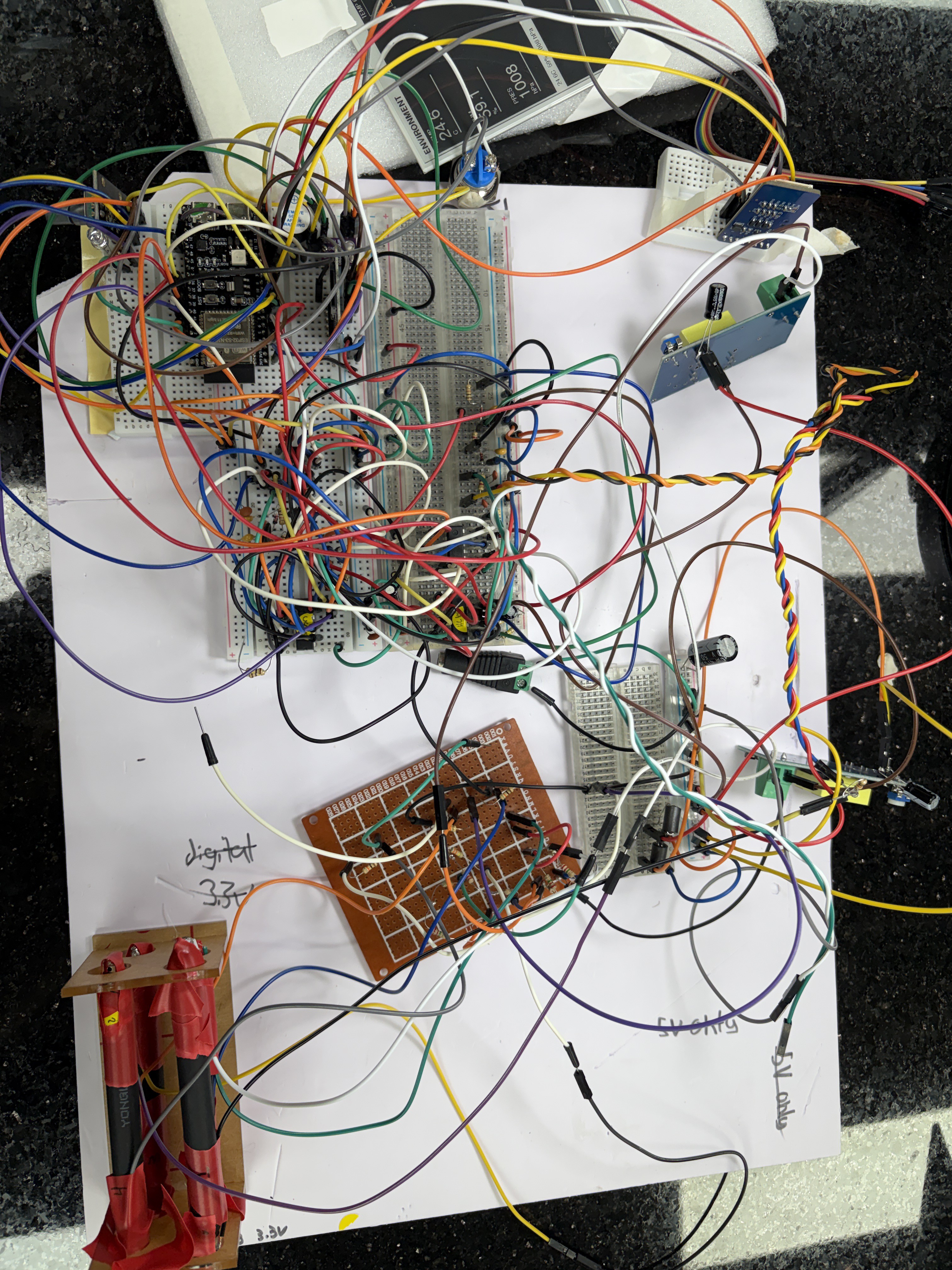
Going from two working tubes to four meant rebuilding the entire analog front end. Two more pulse conditioning channels, two more stretcher networks, and expanding from one coincidence gate to six — one for every tube pair. That took about a week and a half and it was the hardest stretch of the project so far.
Everything that went wrong
My spare HV boost modules got lost in the mail, so I'm sharing one booster per two tubes instead of one per tube. This works, but it means the tubes on a shared supply interact with each other. When one tube fires, the voltage sags briefly and the other tube sees it. With uncalibrated J305s that already have different individual characteristics, this made the count rates confusing to interpret. Is tube 3 reading 40% lower because the tube is weak, because the conditioning circuit is wrong, or because it's sharing a supply with a tube that's hogging current? Hard to tell when three variables are moving at once.
![]()
I lost a full day to my cheap USB logic analyzer. I was using it to monitor signals on the breadboard and was getting unexplainable voltage into the chip it was monitoring. Turns out it was backfeeding power through its input pins; it wasn't just monitoring, it was supplying voltage to parts of the circuit that should have been off. Once I figured that out I had to go back and manually test every channel on both 74HC14s and the 74HC08 gates to make sure nothing had been damaged by the phantom power and that there was no signal leakage between channels.
Then tube 4's 74HC14 channel mysteriously died. Just stopped responding. Replaced the IC, verified the new one, moved on.
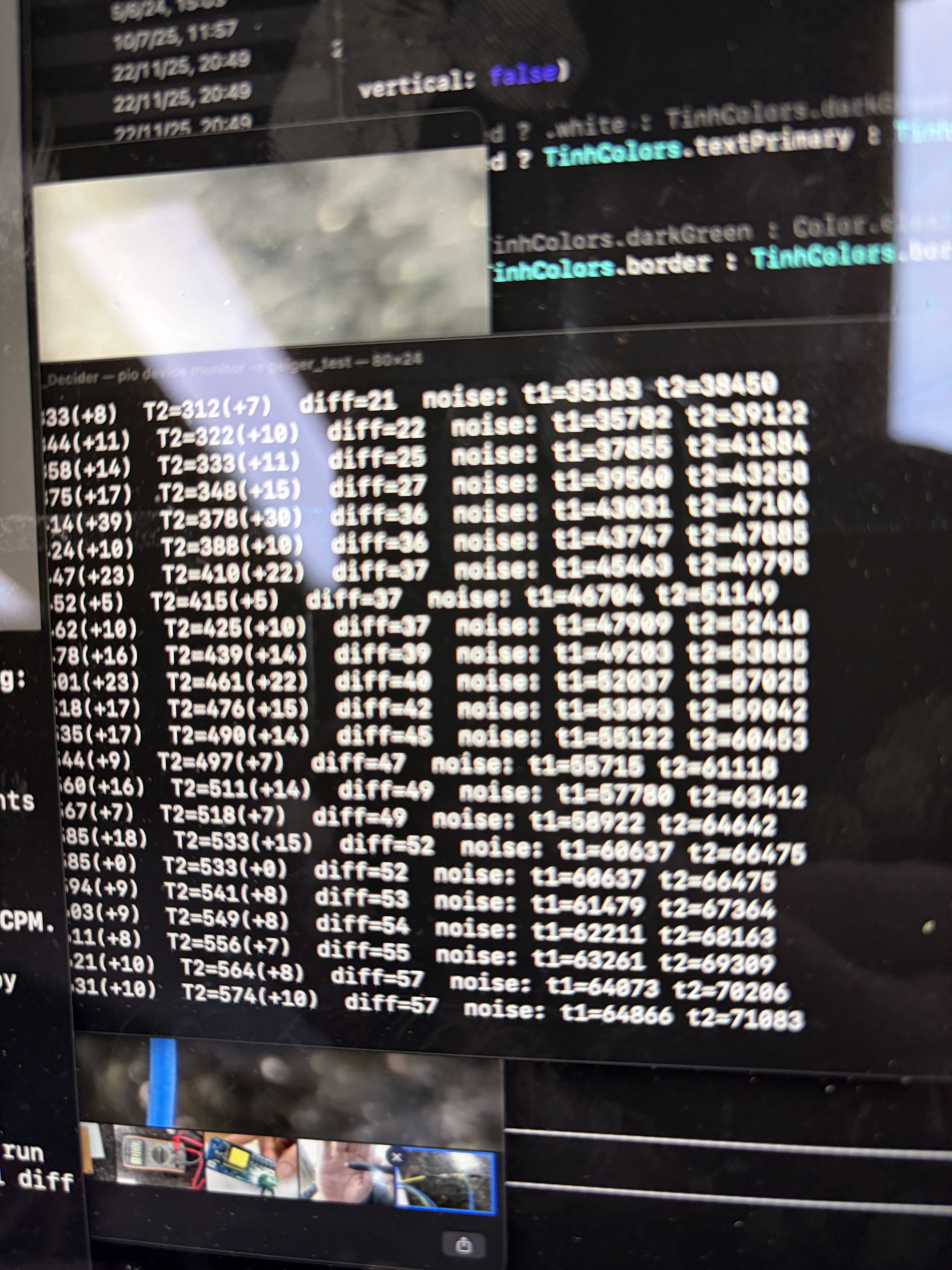
At this point tubes 1 and 2 were counting reliably and their coincidence channel looked clean. But tube 3 was still reading about 40% lower than the other three, and tube 4 would randomly get overwhelmed with noise bursts with counts shooting up to nonsense levels for a few seconds before settling back down.
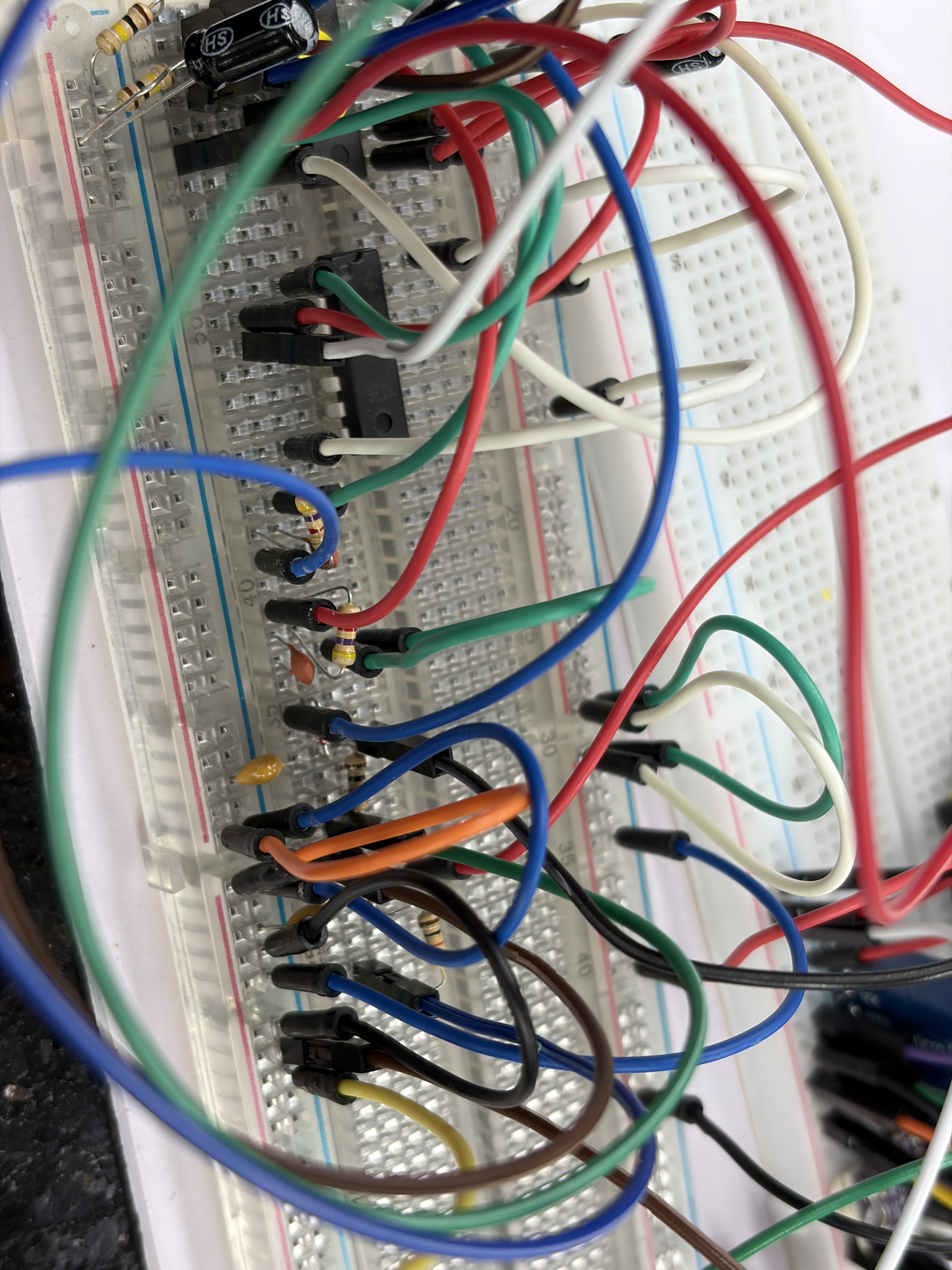
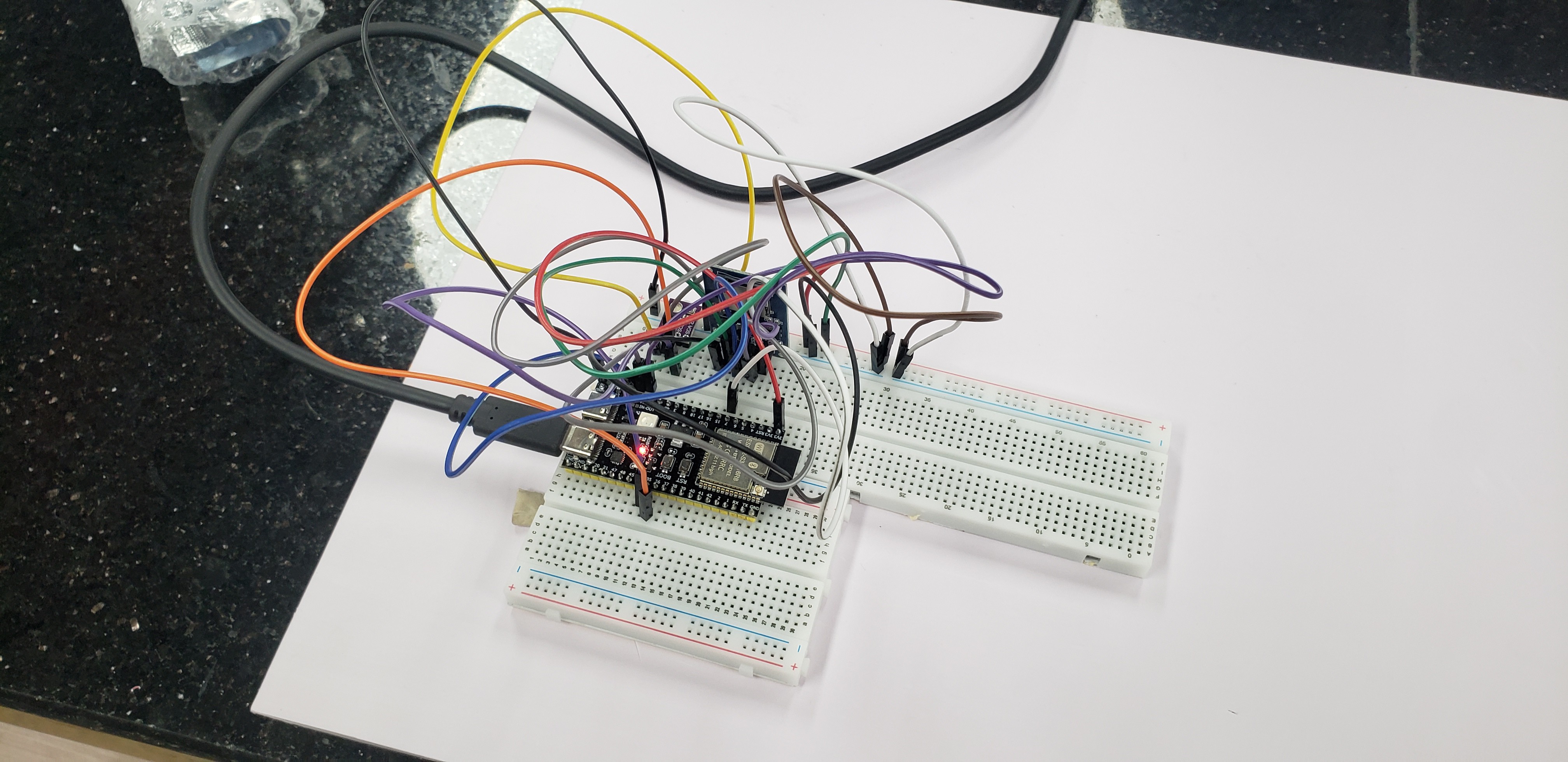
I spent days checking and rechecking. Swapped components, reflowed solder joints, traced every wire. Eventually I documented the coordinates the full breadboard layout and asked Claude Opus 4.7 and GPT 5.5 to look at it. They both identified the same problem: tubes 2 and 3 were getting stuck in logic feedback loops because of a misplaced jumper that was creating a path between two channels that should have been isolated. I'll do a separate post on using AI for hardware debugging because it turned out to be genuinely useful in a way I didn't expect.
![]()
Soak test
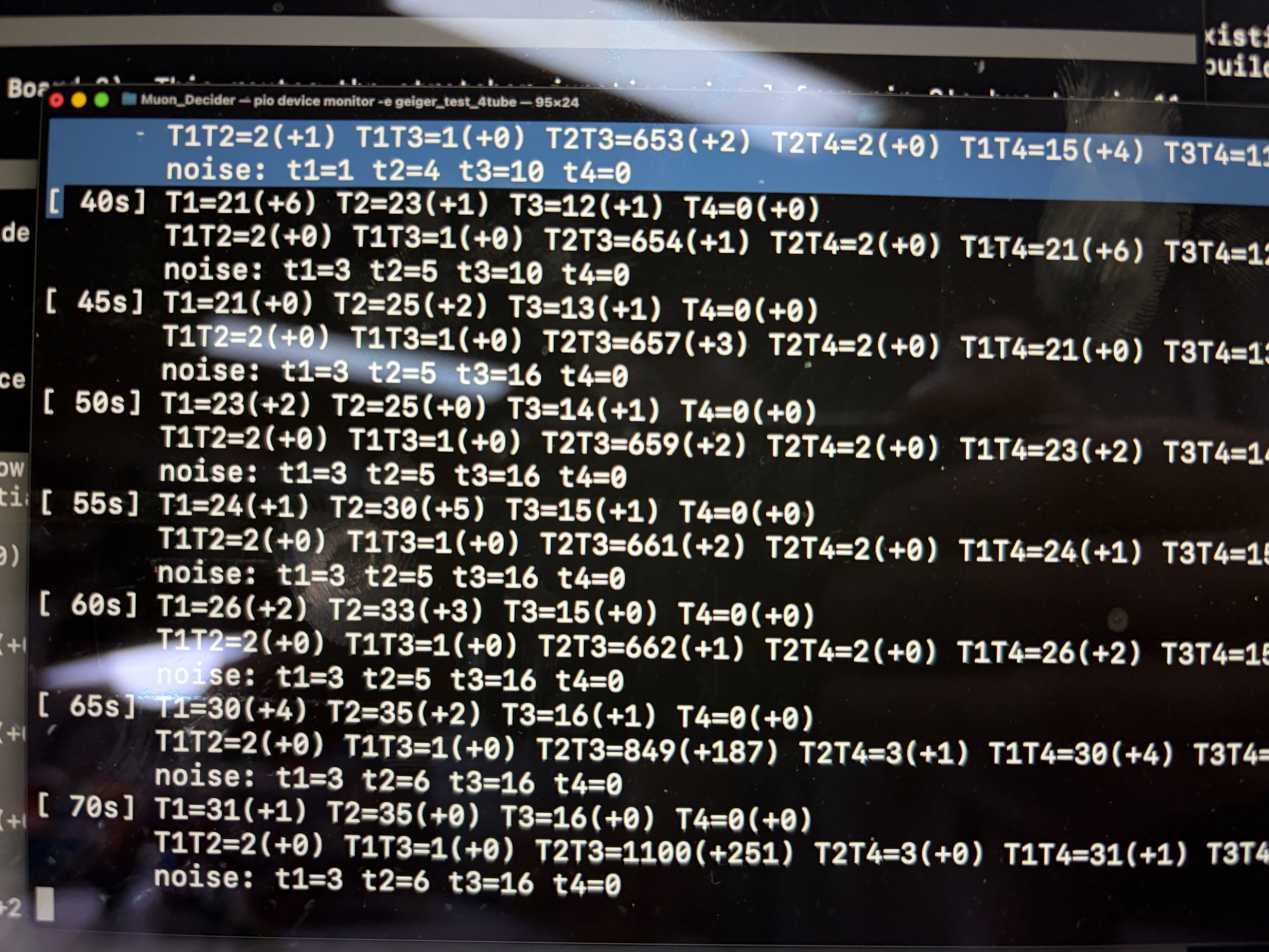
After fixing the jumper issue, all four tubes came online and all six coincidence channels started producing data. I set up an overnight soak test to collect baseline rates for every tube pair at every angle. Seeing six channels and four tubes working smoothly was like a weight off my shoulders. I've been glowing since. This whole project had a question mark above it until that was solved. Everything else after this has error bars squarely in acceptable outcomes.
Results are mostly encouraging. Five of the six channels look stable. But tube 4 had a noise burst in the middle of the night;fd a spike in counts that doesn't correlate with any of the other tubes, so it's not a real radiation event. And tube 3 sagged back down to about 40% of the count rate of the other tubes over the course of the run. So I'm not done yet. Something is still not right with those two channels and I need to go back through the analog front end again.
This is the reality of working with four analog channels sharing two HV supplies on a breadboard. Every time you fix one thing, you find out something else was being masked by the first problem. I'm getting close but I'm not there yet.
![]()
(I'm a teacher building this in my school's maker space so students can see)
Other updates
The e-ink display is still in transit. Once it arrives I'll start building out some features I'm excited about, slow-burn games that live on the e-ink screen and use muon detections as event triggers. Think tower defense or a homestead sim where a couple of things happen each day, driven by cosmic rays. More on that when there's something to show.
I've also started working with a designer on the aluminum enclosure. We're currently evaluating folded sheet aluminum versus an extruded profile, both with different trade-offs in cost, finish quality, and internal layout flexibility. Not my area of expertise but it's moving forward. Updates on that as the design solidifies.
-
From e-ink headaches to high voltage unknowns
05/12/2026 at 08:43 • 0 commentsIt's been a few weeks since the last update and a lot has happened, so this is going to be a longer one covering multiple milestones. I'll try to keep it moving.
The display swap
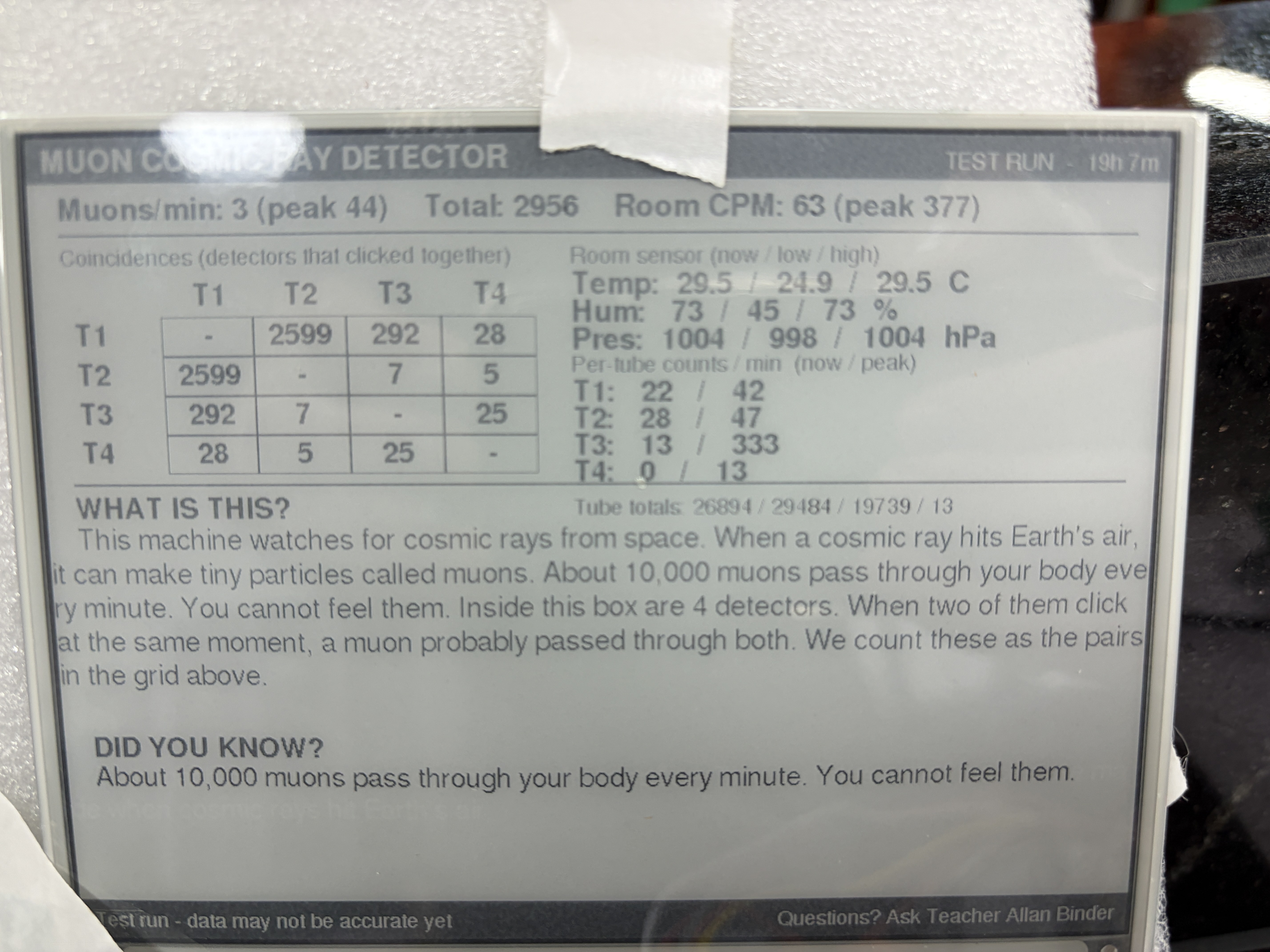
While waiting for the HV boost modules I started working on the e-ink display. I'd originally planned to use a Waveshare 3.97" (800×480, 4-level grayscale) but switched to a Good Display 5.79" wide-format panel (792×272, monochrome) because it had a much faster full refresh on paper (3.5s v 0.7s). Trade-off is losing grayscale, but for a clock and oracle readout, monochrome with good typography is plenty.
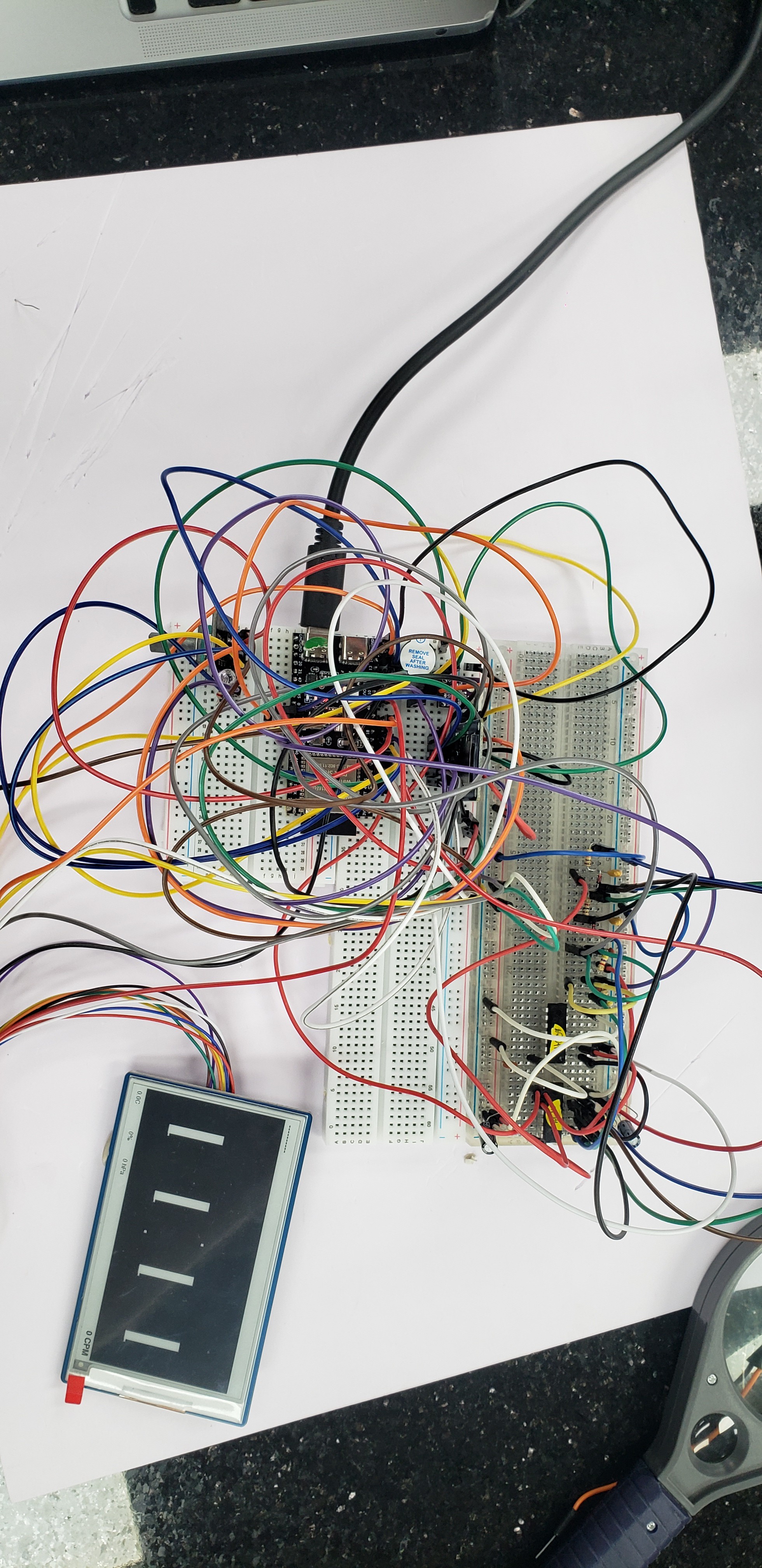
What I didn't expect was spending a full week debugging this thing. I've realized it doesn't do partial updates without RAM buffering, I just assumed it had partial updates, and my little esp32 is just barely enough, so to avoid this again, I just went and ordered an e-reader HD display and we are going to call it a luxury experience. I'll go more into it later, I've put the display on the back burner now that the HV boosters have arrived.
![]()
Laser-cut tube scaffold
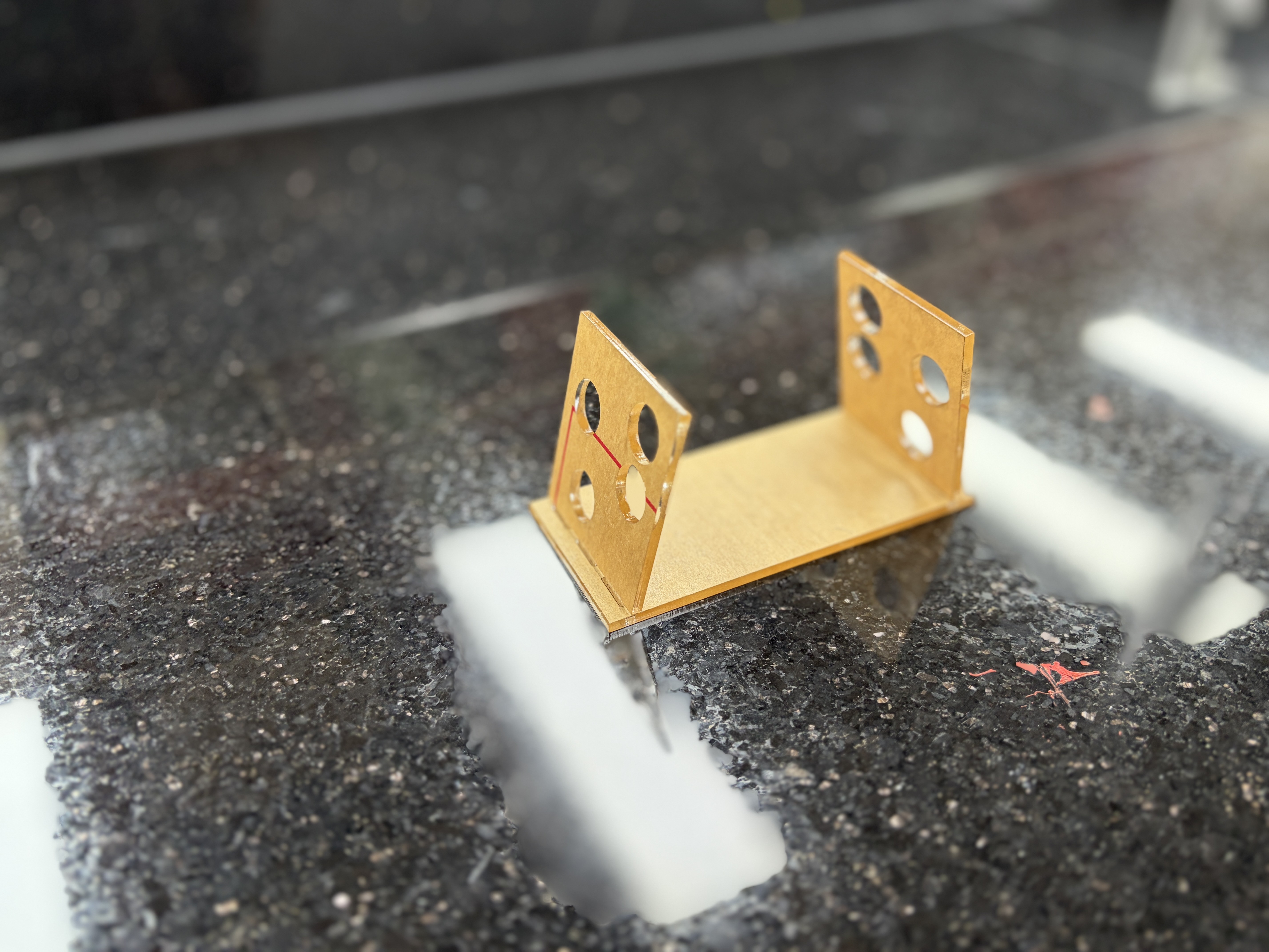
I had an acrylic scaffold laser-cut to hold four J305 tubes for testing. The design puts each of the six possible tube pairs at a different angle with a different geometric aperture, so I can eventually compare coincidence rates across different alignments. The tubes are wrapped in black heat shrink for light shielding (J305s are photosensitive and will false-trigger from ambient light), then taped securely into the cradles.
![]()
Single tube bring-up
The HV boost modules finally arrived and I spent a full day getting a single tube working. It did not go smoothly.
First problem: one of the HV boosters was dead on arrival. No output at all, trimpot did nothing. Swapped it for the second module and got a clean ~410V output. Good reminder to always order spares, I have more on the way.
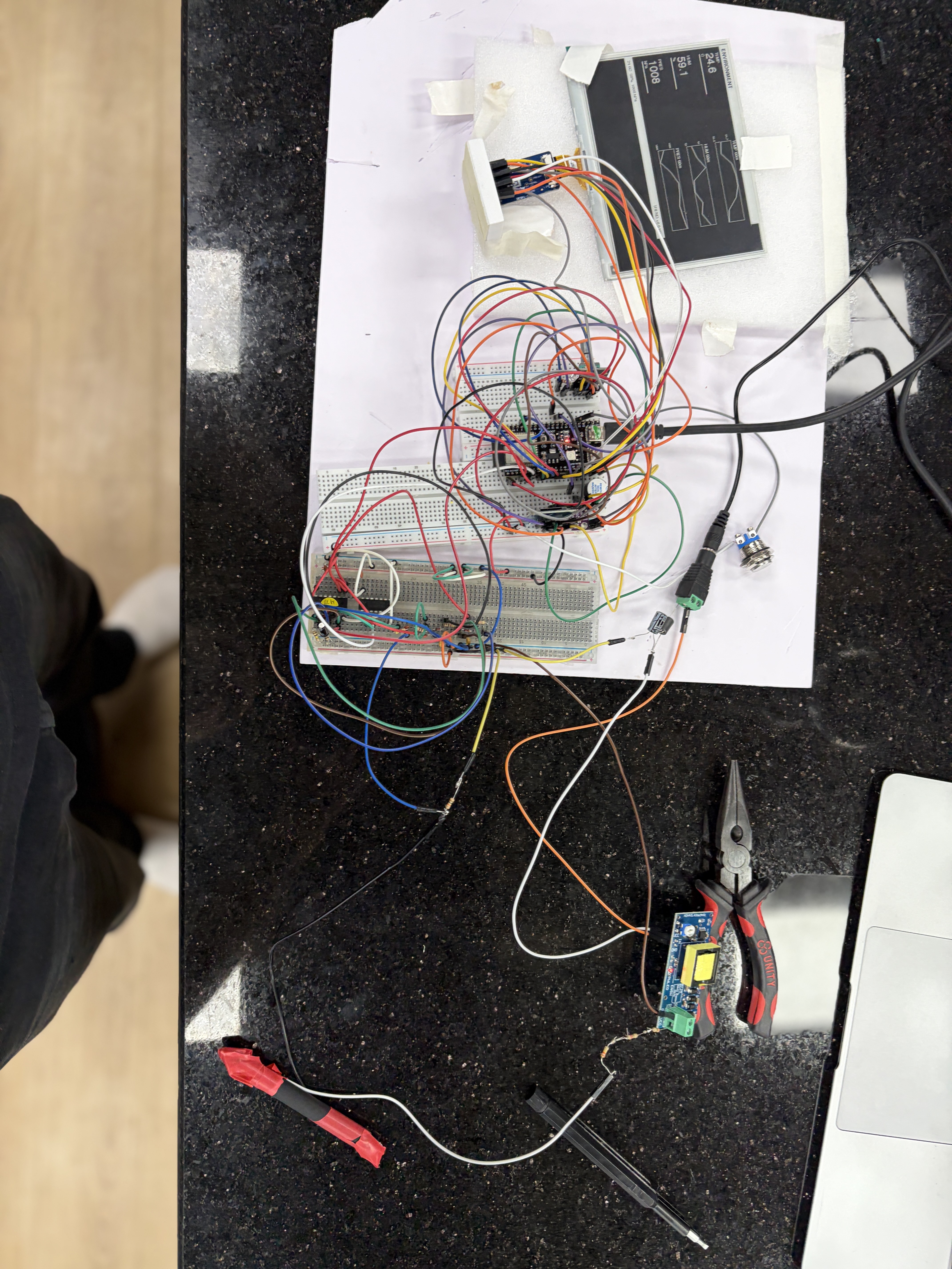
Second problem, and the one that ate most of the day: with a working HV module and a tube connected, I was getting zero signal. The tube was powered, presumably counting background radiation, but nothing was making it through to the ESP32. I went through the chain methodically, checked voltages, checked connections, then checked the 74HC14 inputs and eventually traced it to the pulse stretcher. The BAT54/RC network that worked perfectly with clean synthetic pulses from the ESP32 wasn't behaving the same way with the real analog signal from the cathode. I rebuilt the stretcher section and it started working, I probably had a jumper out of place or something.
That moment when the serial monitor starts printing counts at roughly the right background rate (~25-40 CPM for a J305) is genuinely satisfying. Finally one tube, clicking away, counting background radiation on my desk in Hanoi.
![]()
Two tube rebuild
With one tube proven, I broke down the single-tube setup and rebuilt for two channels. This is where it got messy.
The second channel needed its own pulse conditioning chain which is a coupling cap, bias network, 74HC14 shaping, stretcher, re-squaring, a copy of the first one. And the coincidence gate needed both stretched outputs feeding the 74HC08 AND gate cleanly. In theory I'd already validated all of this with synthetic pulses. In practice, with real analog signals and two HV modules running simultaneously, new problems appeared.
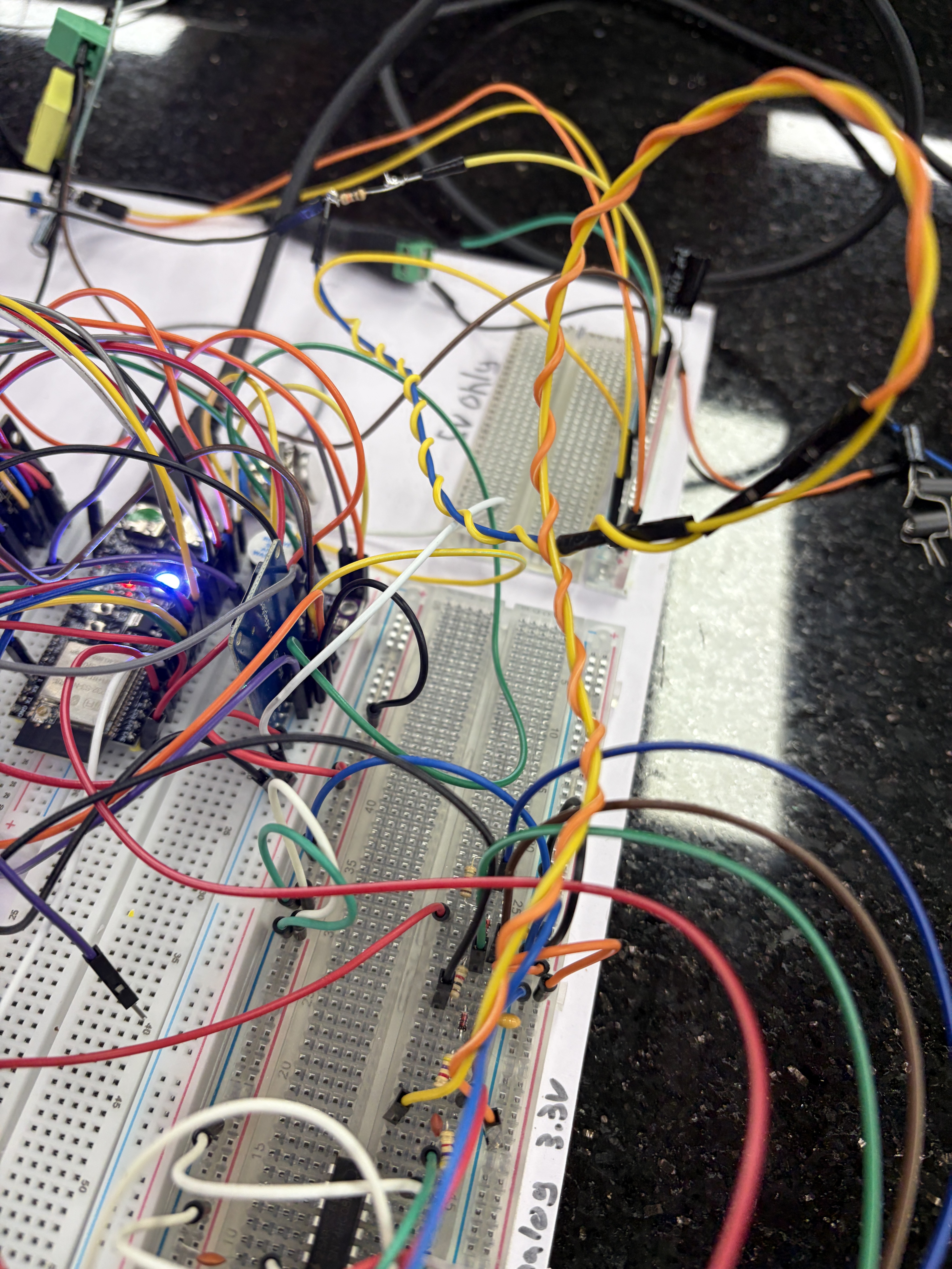
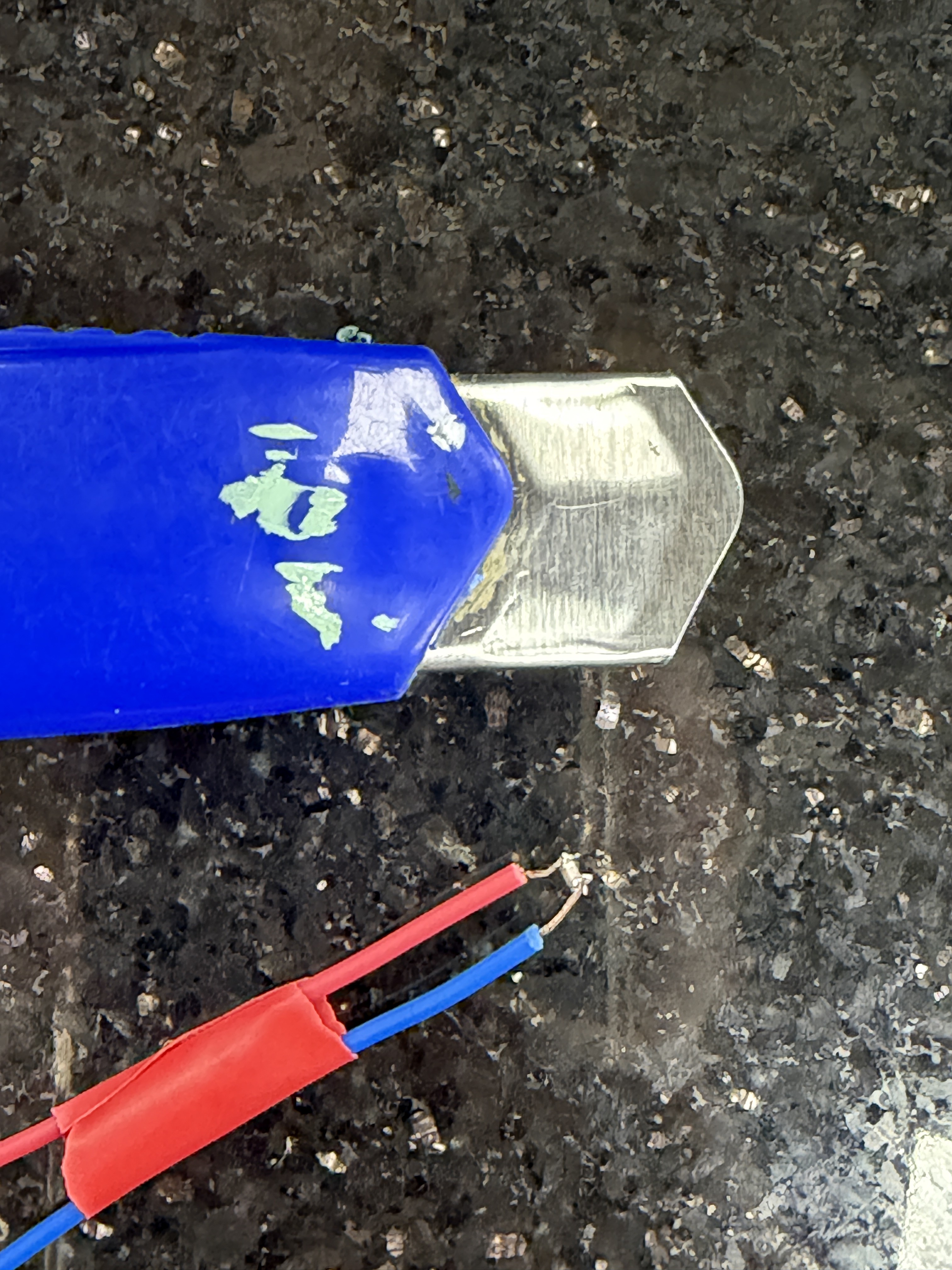
The coincidence timing was off. I was either getting zero coincidences (window too narrow or pulses not overlapping) or suspiciously high counts that were clearly noise rather than real events. First I was getting 1000+ hits a second, which was clearly noise. I wrapped the cathode lines with grounded cables, that brought it down to 200ish.
![]()
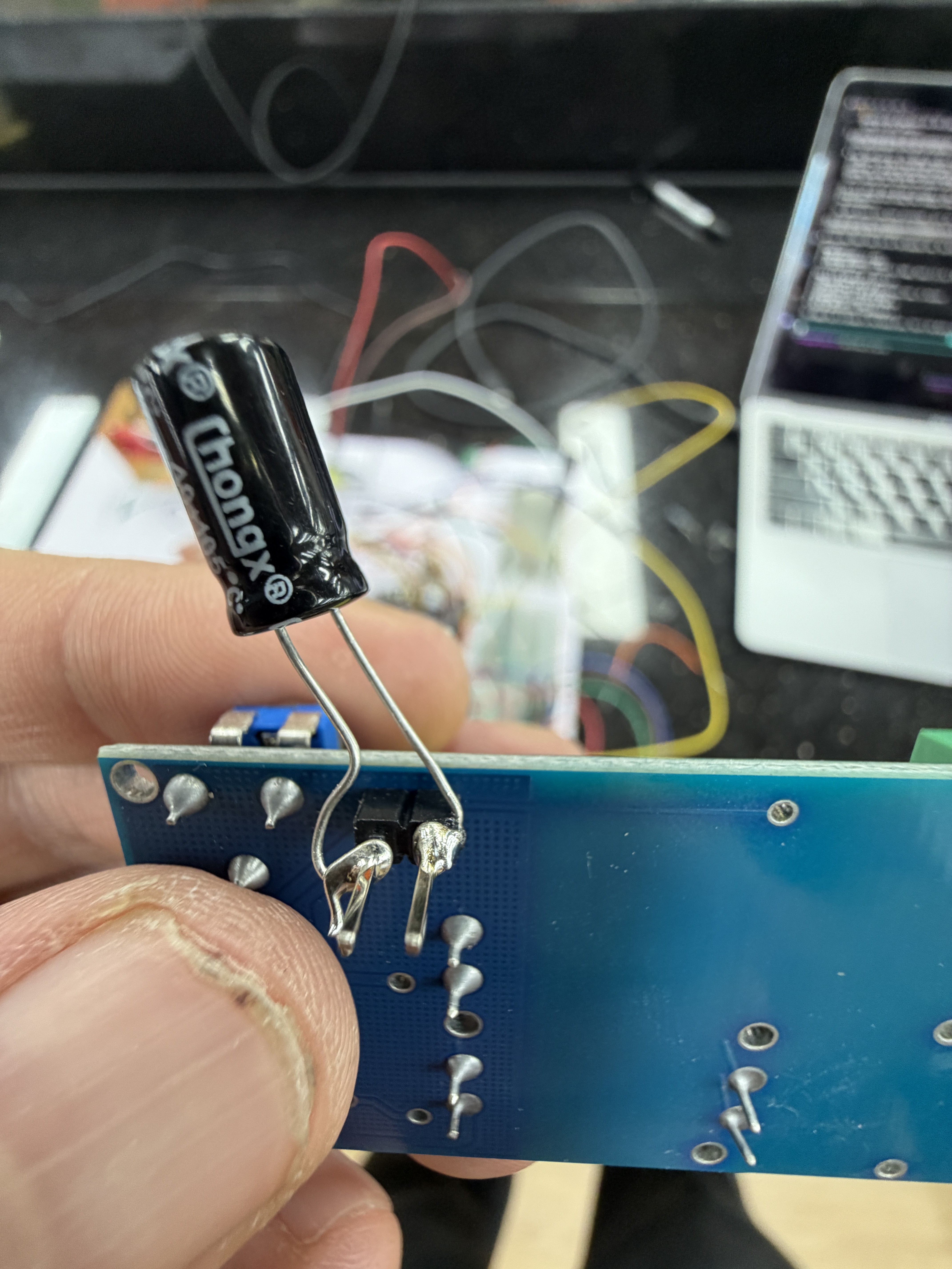
Then I threw a capacitors the HV boosters inputs (which felt so wrong)
![]()
That brought it down to around 30, I tried to solder up a tiny 100pf ceramic cap and it was a joke lol didn't do anything. Interestingly enough claude recommended ferrite beads on the input of the 5v/vcc of the hv boosters but they didn't really do anything.
![]()
In the end it turned out that I forgot to ground out the unused U2 (74HC08) pins, and that got rid of all of the noise, but tube 2 was still not giving proper pulses when I had to clean up for the day.
More soon, hopefully muon detection in the next post
-
Testing the signal chain with synthetic pulses
05/06/2026 at 03:35 • 0 commentsBefore the HV boost modules arrive (40 days in transit), I wanted to validate as much of the detection circuit as possible using just the ESP32 itself. The idea is simple: use one GPIO as a signal generator to inject fake pulses into the front end, and use another GPIO to listen for interrupts at the output. If the right number of pulses come out the other end with the right timing, the chain works.
Digital chain first
![]()
I started with just the digital side, the 74HC14 pulse shaping, BAT54/RC stretcher, second 74HC14 re-squaring stage, and the 74HC08 AND gate. I wrote a quick sketch that toggles a GPIO to produce short pulses at a known rate, fed those into the 74HC14 input, and counted rising-edge interrupts on the AND gate output with a separate pin.
For single-channel testing I injected pulses into one channel at a time and confirmed the ESP32 counted every one. For coincidence testing I fed the same pulse into both channels simultaneously. The AND gate output fired on every injected pulse, which is exactly what you'd expect when both inputs see the same signal at the same time. I also confirmed that pulsing only one channel produced zero coincidence counts on the output. That's the whole point of the AND gate and it's reassuring to see it actually reject single-channel events.
Not the most sophisticated test, a logic analyzer would let me see the actual pulse shapes at each stage and verify the stretcher timing. But for a go/no-go check of "is this circuit wired correctly and are the ICs behaving," it's enough. The logic analyzer is sitting on my desk for when I need it later.
Then the analog front-end
![]()
With the digital chain proven, I wired up the analog input network: the 1nF coupling caps, 4.7kΩ series protection resistors, and 100kΩ bias pull-downs that sit between the GM tube cathodes and the 74HC14 inputs. No tubes, no HV, just the passive components that will eventually condition the real cathode pulse.
Same test: synthetic pulses from the ESP32 into the analog input side, interrupt counting on the coincidence output. The pulses now travel through the full path, coupling cap, bias network, first Schmitt trigger stage, stretcher, re-squaring, AND gate. Everything that isn't the tube and HV module.
It worked. Same pulse counts in, same counts out. The coupling caps and bias resistors aren't filtering out or attenuating the synthetic pulses, which makes sense because the ESP32 GPIO puts out a clean 3.3V edge that's well above the 74HC14's ~1.9V threshold. The real question is whether actual GM tube cathode pulses will be strong enough, and that's something I genuinely won't know until the HV modules show up and I can power a tube.
That's the next milestone: HV module bring-up. The boost converters are still in transit, so in the meantime I've been working on the e-ink display which turned into its own adventure. More on that next time.
-
Digital Circuits Breadboarded
05/04/2026 at 03:24 • 0 commentsWith the schematics drawn and parts sorted into their labeled bins, it was finally time to start populating a breadboard. The plan was to build the entire digital chain first; pulse shaping, stretching, re-squaring, and the coincidence AND gate. Without any of the analog front-end and definitely without any HV anywhere on the bench.
I'll spoil the post: it was uneventful. Which is the goal, honestly. The fun part of breadboard work is that satisfying click of components going into rows and the slow accumulation of a circuit that starts to look like the schematic on paper. Two 74HC14s, a 74HC08, a 100nF decoupling cap on every IC's VCC pin (every IC!!), the BAT54 diodes and RC networks for the stretchers, all the bias and pull-down resistors. About an hour of work, a couple of moments where I had to recount pin numbers, and a finished chain.
A few small choices worth calling out:
The BAT54s are SOT-23 SMD parts, which is annoying on a breadboard. I soldered short lead wires onto each one before plugging them in. Ugly but functional, and they'll be replaced with through-hole packages once the design moves to PCB anyway.
I tied all unused 74HC14 and 74HC08 inputs to ground rather than leaving them floating. CMOS inputs that float pick up noise and can self-oscillate, which is exactly the kind of subtle problem you don't want chasing later when the analog side is also misbehaving.
I left the cathode pulse inputs (TUBE1_RAW and TUBE2_RAW on the schematic) terminated at unused breadboard rows for now. Those will get connected to the GM tubes once the analog front-end exists. Until then,they're just landing pads waiting for a signal.
![]()
Next post is going to be the more interesting one: validating that the chain actually works using synthetic pulse injection. I'm generating test pulses from an ESP32 GPIO and walking through the chain stage-by-stage with a logic analyzer to make sure each transformation happens the way the schematic says it should. That's the post where I find out if I drew the circuit correctly.
-
Designing a cosmic ray decision oracle on paper
04/22/2026 at 06:40 • 0 commentsI have been thinking about building a Muon based RNG device ever since watching an Alpha Phoenix video on Youtube. It seemed like such a cool way to have a direct connection to both sub-atomic and astronomical scales. I mulled the idea around for ~2 years and finally decided to pull the trigger.
I haven't designed a circuit from scratch since high school, but I have done a number of repairs on analog equipment working as a sound engineer over the years, so the first thing I wanted to do was draw out the schematics to make sure I understand everything and can start preparing myself mentally for dealing with analog components without an instruction manual. Specifically because the 2x (I've updated the design to use 4x, not pictured in these drawings) high voltage boosters are not something you can really troubleshoot on the breadboard without burning the rest of the hardware.
Next week: the digital chain on breadboard, validated with a synthetic pulse injector before any HV comes near it.
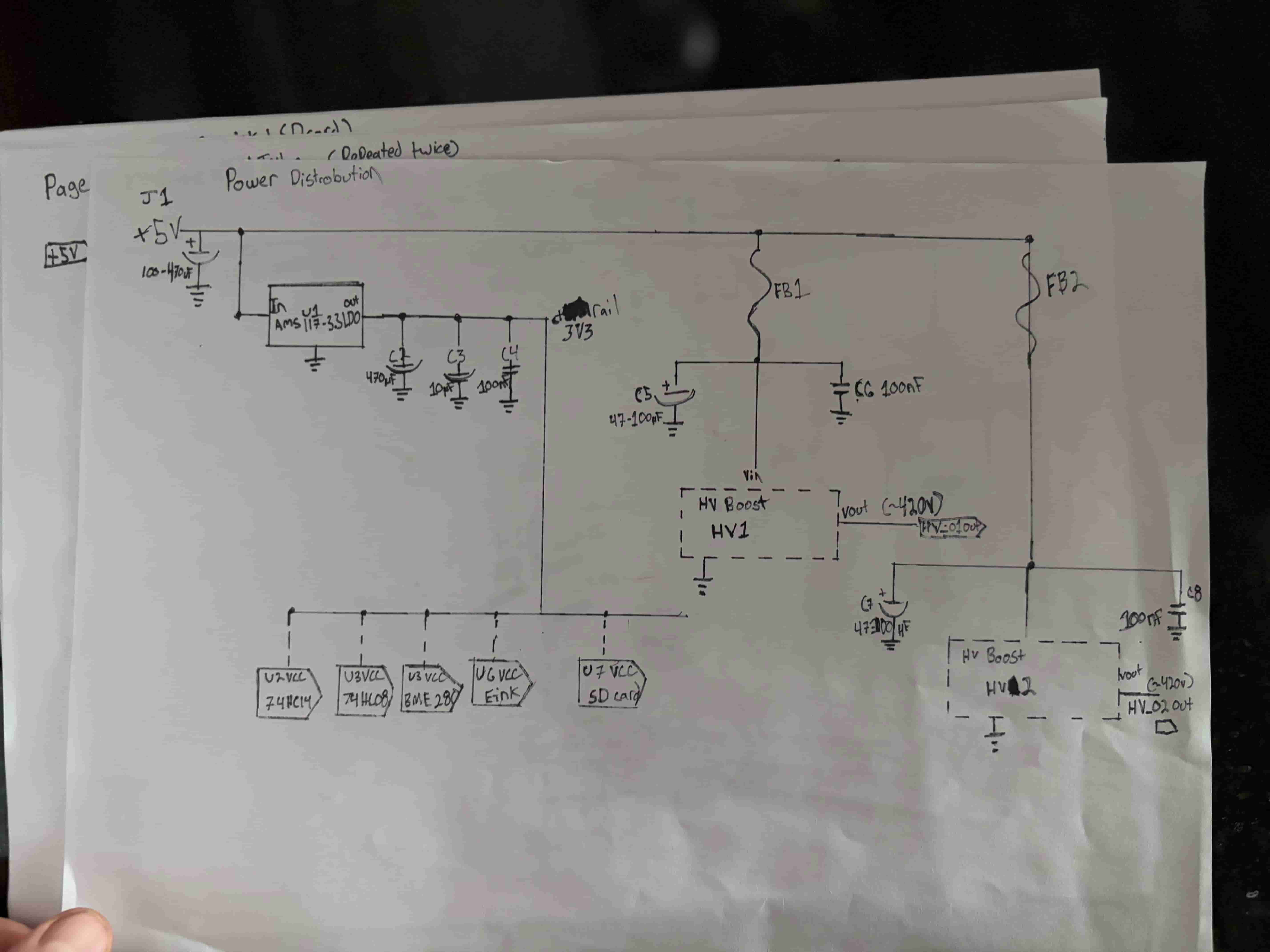
Page 1 of the sketch set. USB-C 5V in, AMS1117 LDO dropping to 3.3V for peripherals, ferrite beads isolating the two HV boost modules so their switching noise stays out of the logic rail. 
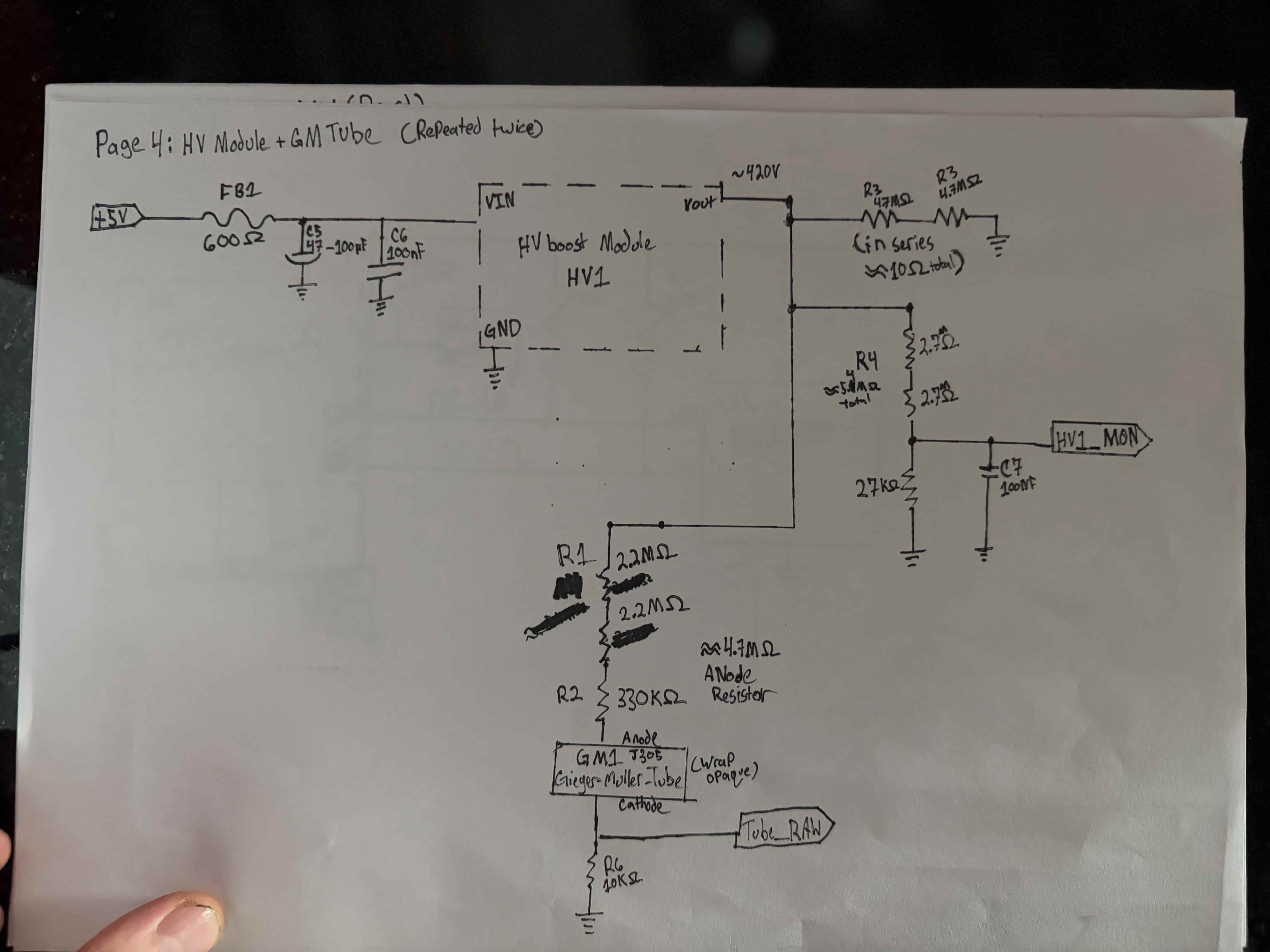
Page 2, repeated for both tubes. HV module trimmed to ~420V, series-stacked resistors on the anode and bleeder (no single resistor sees more than its rated working voltage), and a divider down to ~2.2V for the ESP32 ADC to monitor. The tube cathode is where the signal is picked off, not the anode. 
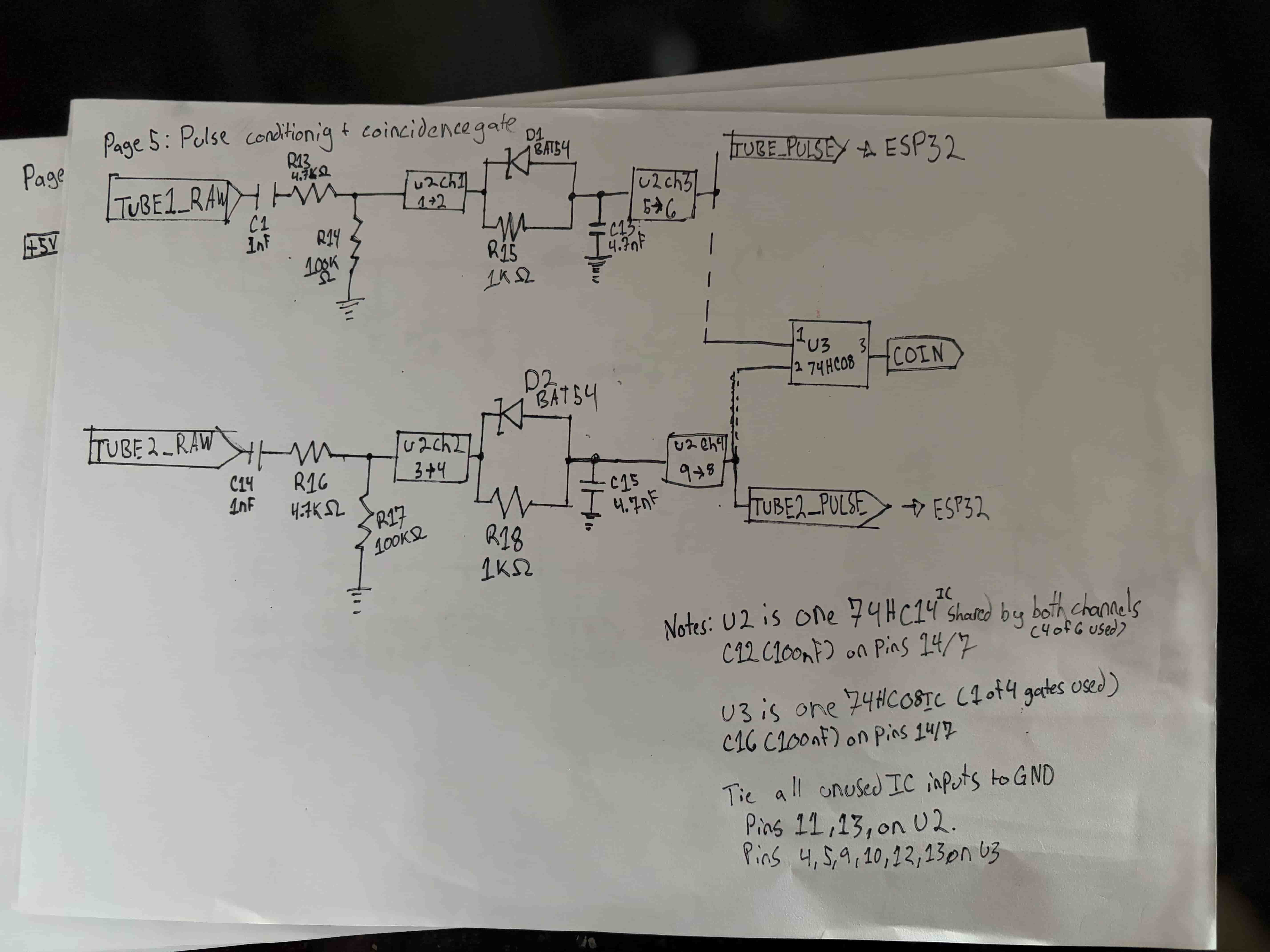
Page 3, the heart of the detection circuit. Each tube's cathode pulse gets AC-coupled, shaped through a 74HC14 Schmitt trigger, stretched with a BAT54 diode and RC network to ~3-5µs, then re-squared through another 74HC14 channel. Both stretched pulses feed a 74HC08 AND gate. Its output fires only when both tubes trigger within the coincidence window which is the muon signal. 
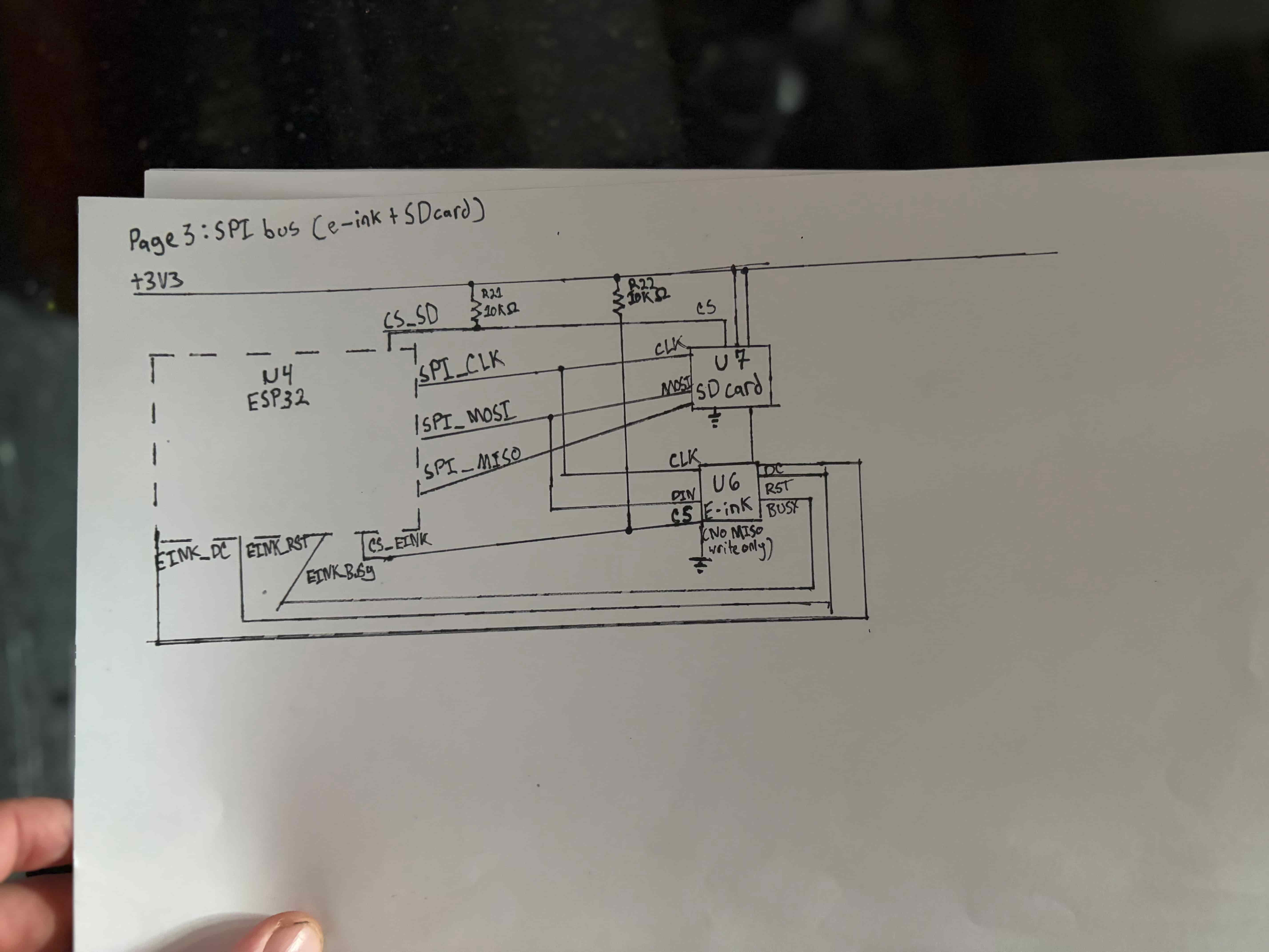
Page 4. The e-ink display and SD card share MOSI and CLK but get their own chip-select pins (with pull-ups so both stay deselected during boot). Only the SD card uses MISO — the e-ink is write-only. 
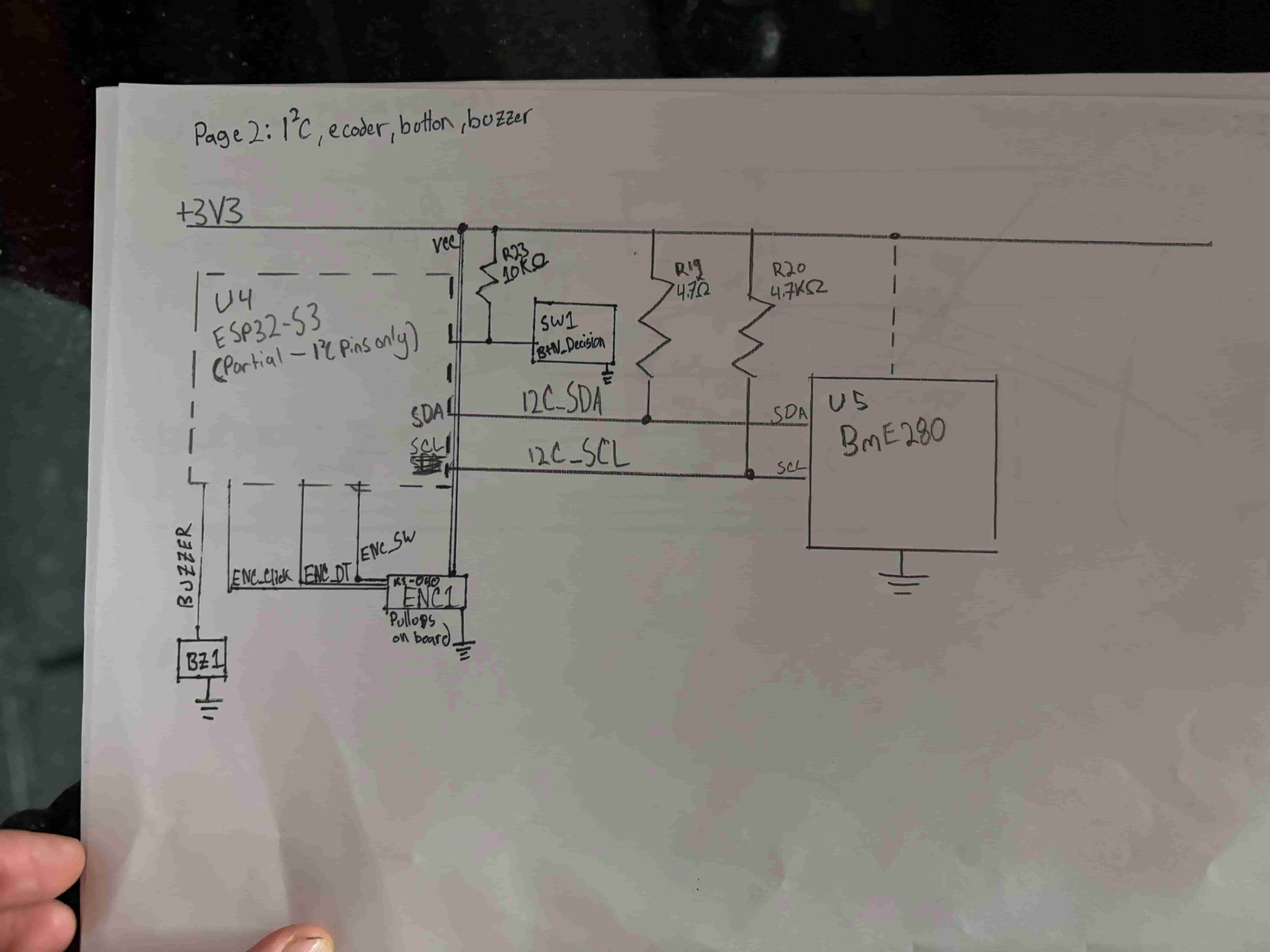
Page 5. BME280 environmental sensor on I²C, KY-040 rotary encoder for navigation, dedicated decision button (the hero interaction so it's kept physically separate from the encoder), and a passive piezo for audio feedback. 
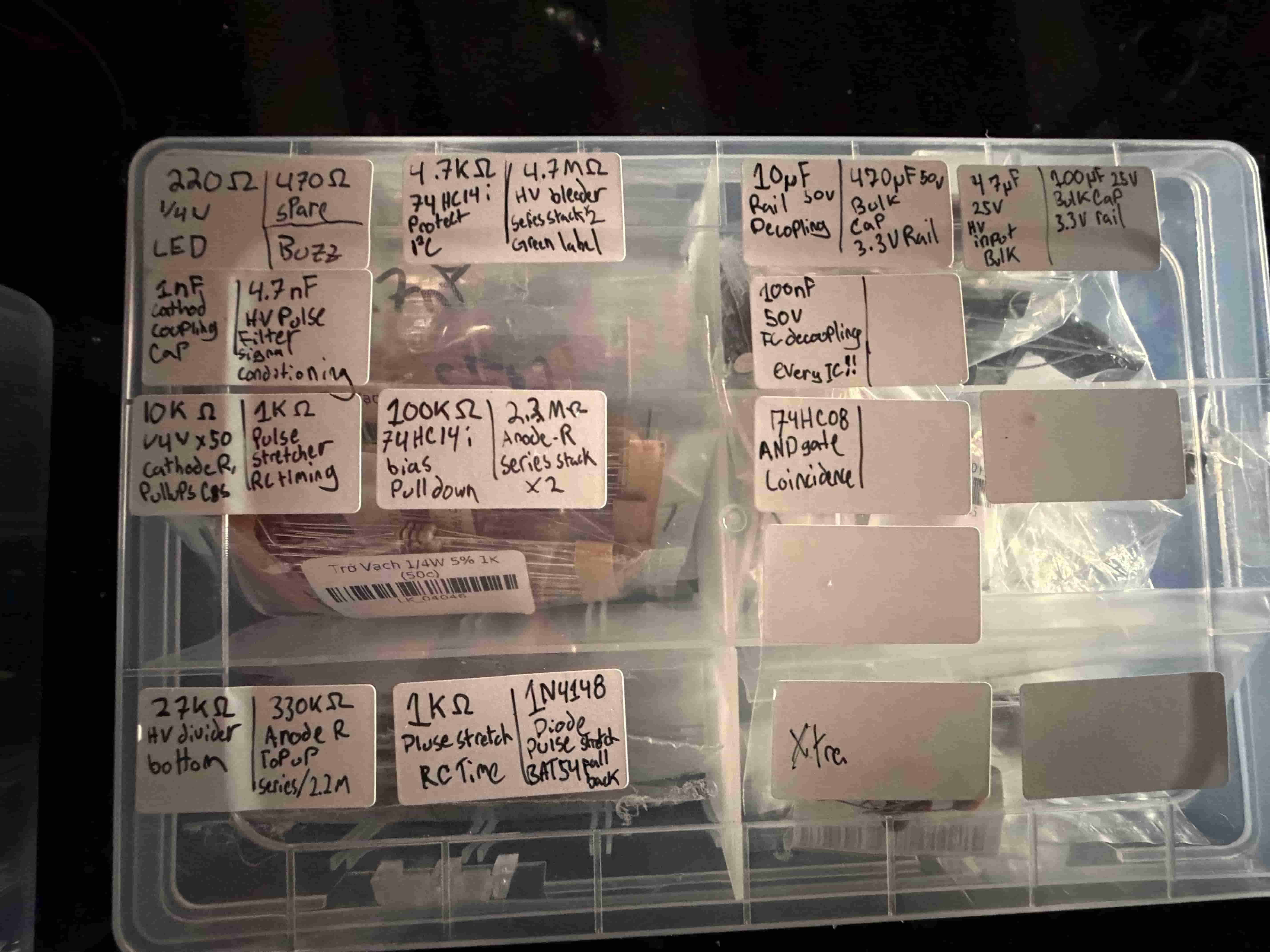
Every component bag hand-labeled with value, purpose, and where it goes in the circuit. "100nF -> IC decoupling -> every IC!!" is for future me at 2am who forgot to drop a cap next to a chip.
*Missing page 6, the ESP32-S3 pinout map. Forgot to photograph it.
Muon Sortes
Using a custom six channel muon detector to create a cosmic oracle experience with a high quality e-ink display.