 Sergei

Why I built DOGS²
There is never enough space on my workbench, I sometimes work in the field, and my laptop's USB ports are occupied. Reading one UART line can mean finding an adapter and cable, freeing a port and opening another terminal window.
I wanted one small instrument powered by almost any available source that could replace several small instruments, adapters and cables.
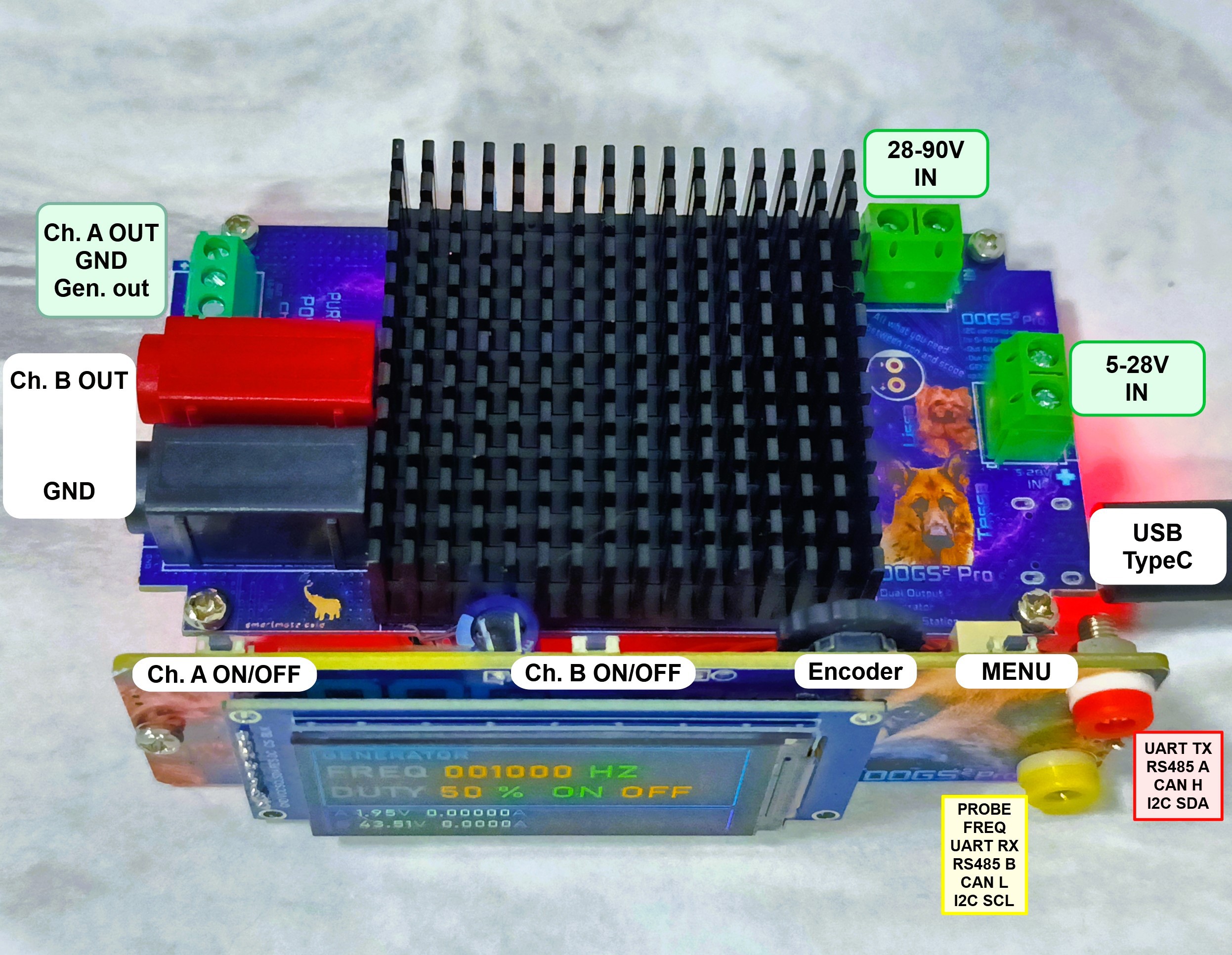
Two power channels
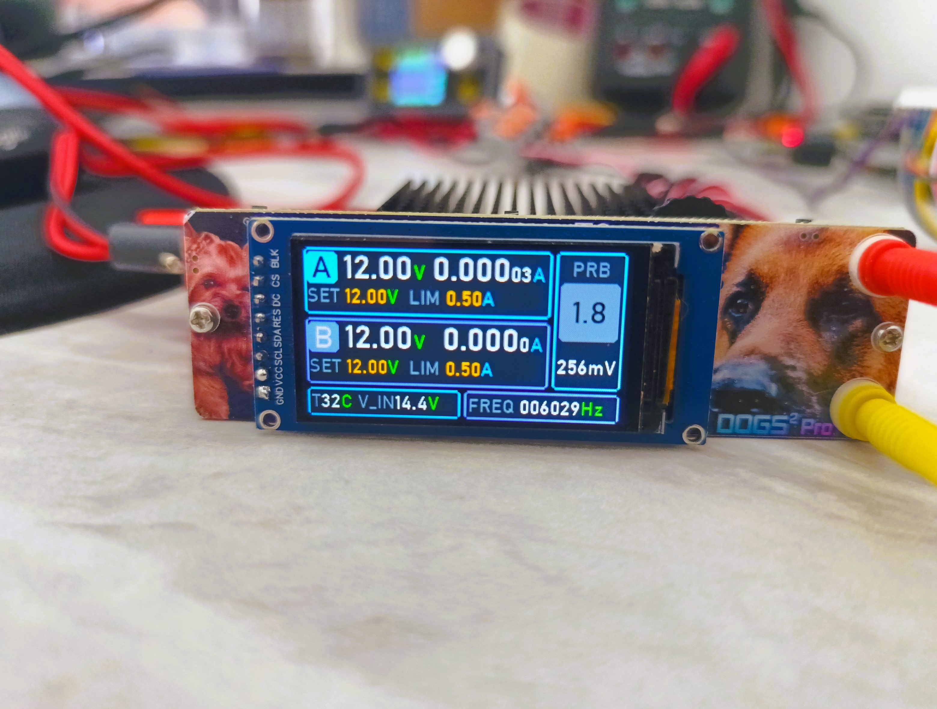
DOGS² has two independently adjustable CV/CC channels with a common ground.
| Section | Specifications |
|---|---|
| Channel A | Low-noise linear regulation, up to 20 V / 1.5 A. Current-measurement LSB is 12.5 µA below 400 mA and 50 µA above 400 mA. |
| Channel B | DC/DC conversion, up to 48 V / 3 A continuously or 5 A for short periods. Current-measurement LSB is 125 µA. |
| Input power | 5–90 V DC or USB Type-C, including power from car and motorcycle batteries. Protected against overvoltage, reverse polarity and inrush current. |
Both channels measure output voltage and current.
Total power depends on the input source.
The outputs are not galvanically isolated.
The stated limits and accuracy apply to the v1 engineering version and are still being refined through calibration, converter tuning and load tests.
Measurement and signal generation
- LOW / High-Z / HIGH logic probe with voltage measurement up to 25 V; output-resistance estimation is under development;
- frequency counter up to 100 kHz;
- square-wave generator from 1 Hz to 100 kHz, 1–99% duty cycle, up to 1 A and up to 20 V as set by Channel A.
Digital interfaces and Bluetooth
| Interface | Functions | Parameters / status |
|---|---|---|
| UART / RS485 | Terminal | 2.4–115.2 kbit/s |
| LIN | Sniffer | TBD |
| CAN | Terminal: receive, filter and transmit | 11-bit ID, 125–1000 kbit/s, configurable mask |
| I2C | Terminal, scan and sniffer | Configurable address mask |
| 1-Wire | Decoder | TBD |
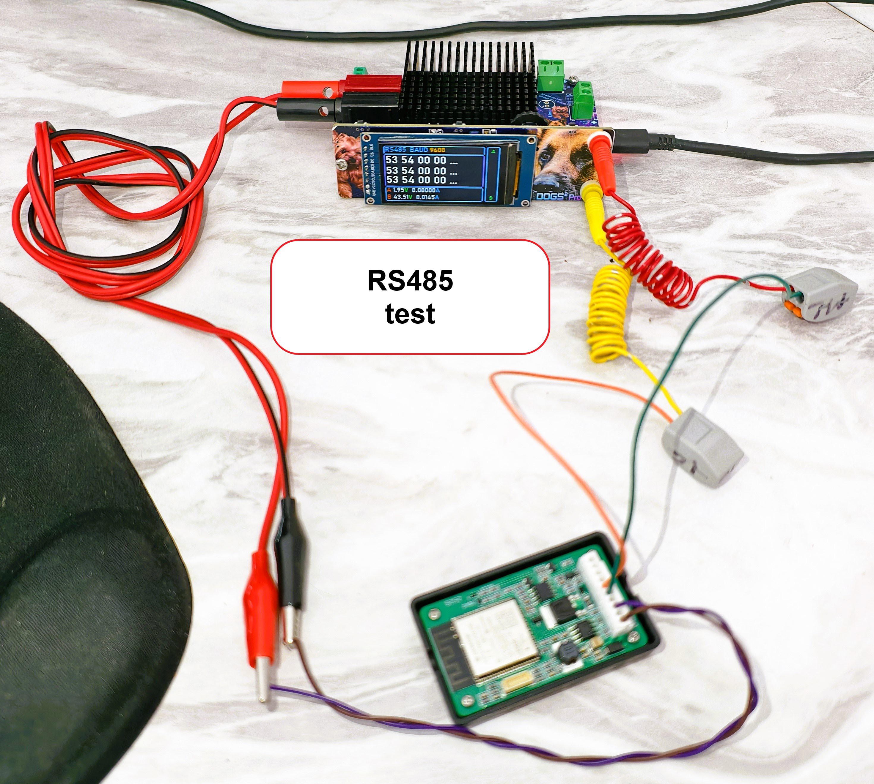
Terminal and sniffer data use a simple text command protocol over Bluetooth SPP. Incoming data can be monitored on the display, but composing and transmitting packets is done from a phone terminal, I currently use Serial Bluetooth Terminal Android app.
Current readings from both channels can be graphed in Bluetooth Graphics Android app, adjustable graph sweep speed is being implemented.
Architecture and current status
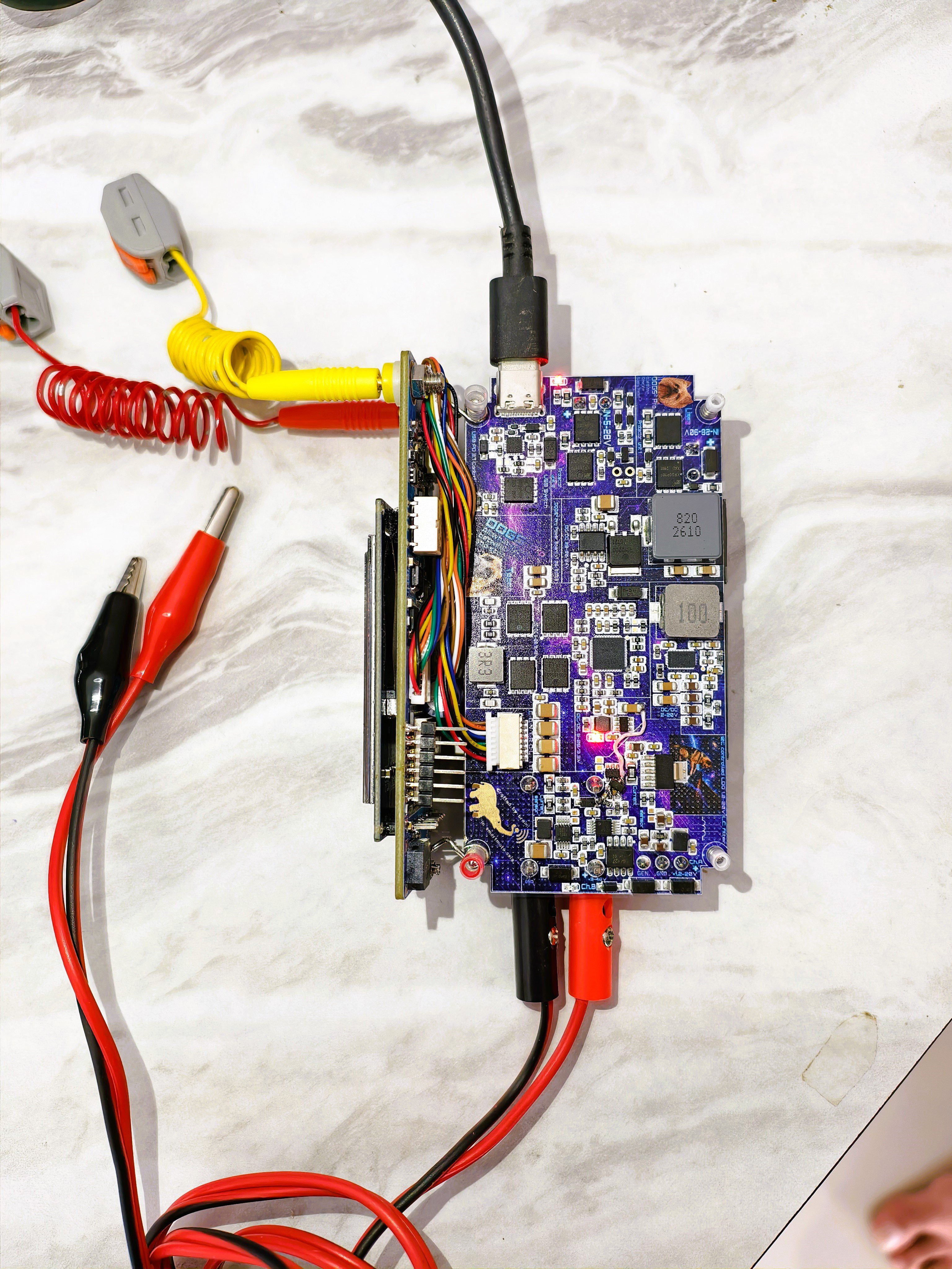
The instrument is divided into a power board and an ESP32-WROOM control panel. The former contains the protected inputs, converters, Channel A linear stage, measurements and generator power stage. The latter carries the display, controls, probe, counter and interface drivers.
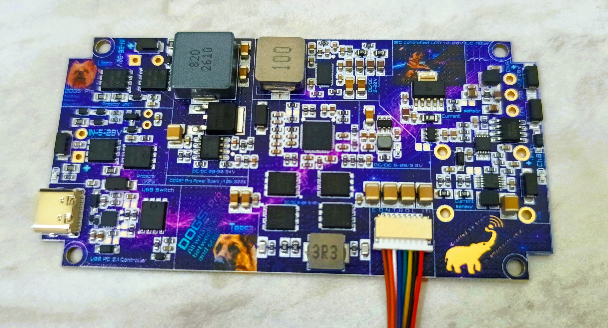

Five DOGS² v1 engineering samples have been assembled and run the latest firmware. Both power channels, measurements, logic probe and voltmeter, generator, frequency counter, UART, RS485, CAN, I2C sniffer, I2C master and Bluetooth are working.
Current work includes selecting better DC/DC compensation networks, finding the actual operating limits and lowest output voltages, thermal tests, software refinement, a transparent-plastic enclosure, documentation, external beta testing and possibly a dedicated mobile application.
This is working hardware, but still an engineering sample rather than a finished product. I will publish successful demonstrations as well as limitations, v1 mistakes and measurement results.
Open source
DOGS² v1 hardware uses the CERN Open Hardware Licence Version 2 — Weakly Reciprocal. The repository contains schematics, block diagram, editable EasyEDA source, manufacturing files, board renders, current ESP32 firmware and known issues.
Why DOGS²?
DOGS² stands for Dual Output Generator Supply Station. The name is also dedicated to my two dogs—Tessa, a German Shepherd, and Lissa, a Yorkshire Terrier—whose portraits appear on the boards. This does not improve the electrical specifications, but it makes the instrument a little less impersonal.
What comes next
I will publish test results, discovered limitations and changes...
Read more »