Dzmitry Dydyshka
-
Adding Auto-ranging to the PSU-EXT Analog Front End
09/13/2026 at 05:34 • 0 commentsPSU-EXT sits between an existing bench power supply and its load. It measures voltage and current and controls the output path with a relay. This update follows the development of its voltage measurement front end, from fixed converter settings to automatic range selection and programmable acquisition speed.
![]()
The existing design works with a fixed programmable gain amplifier (PGA) setting and a fixed analog-to-digital converter (ADC) rate. Its DC voltage accuracy is:
- ±(0.1% of reading + 2 mV) from 1 V to 24 V
- ±(0.5% of reading + 2 mV) below 1 V
That gives us a useful starting point. The next step is to use more of the ADS1115's capabilities: select a measurement range automatically and let the acquisition speed suit the task. Following that idea through the firmware led to two additions to the analog circuit: voltage buffers and a negative-rail output bias.
Making the Converter Settings Programmable
The ADS1115 has several full-scale input ranges. A smaller range gives a smaller voltage step per ADC count, which is useful when measuring low voltages. Autoranging lets the firmware select a narrow range for a small signal and move to a wider range as the signal rises.
The updated firmware uses three ranges: ±0.256 V, ±0.512 V, and ±2.048 V. These are voltages at the ADC input, after the voltage divider.
The range selection code moves one range at a time. Separate thresholds for moving up and down provide hysteresis, so a reading near a boundary does not repeatedly switch ranges. This excerpt comes from components/measure_svc/measure_prov_ads1115.c:
uint8_t index = current_index;
if ((index + 1U < ADS1115_RANGE_COUNT) &&
    (adc_voltage_u4 >= ADS_RANGES[index].hysteresis_top_u4)) {
    ++index;
} else if ((index > 0U) &&
    (adc_voltage_u4 <= ADS_RANGES[index].hysteresis_bottom_u4)) {
    --index;
}
*next_index = index;
Each input keeps its own range index. The firmware can therefore choose a range independently for each measured signal.
Acquisition speed is now programmable too. The driver accepts the ADS1115 rates of 8, 16, 32, 64, 128, 250, 475, and 860 samples per second. For example, these cases encode two rates into the configuration register:
case 128U:
    *bits = (uint16_t)0x04U << 5;
    return ESP_OK;
case 250U:
    *bits = (uint16_t)0x05U << 5;
    return ESP_OK;
These settings control the converter rate. The update rate for a complete set of measurements also depends on channel scanning and settling conversions.
The new Standard Commands for Programmable Instruments (SCPI) command exposes this setting to users:
Command Description MEASure:ADC:RATE <SPS> Set the ADC conversion rate in samples per second MEASure:ADC:RATE? Read the selected rate as an integer Following the Signal Back to the Divider
During development of the programmable-rate mode, changing the ADC rate also changed the voltage reading for a steady input. The current channel, driven by an INA240 current-sense amplifier, stayed stable in the same experiments. That difference pointed us toward the circuit driving the ADC.
Each voltage channel uses two 160 kΩ resistors above a 20 kΩ resistor. The nominal division ratio is 17:1. At a 30 V input, the divider produces about 1.765 V while drawing about 88 µA.
Rsource = 320 kΩ || 20 kΩ ≈ 18.8 kΩ
The ADS1115 uses a switched-capacitor input. Its input loading interacts with the resistance of the source driving it; The ADS1115 datasheet describes this behavior. The observed rate-dependent shift made source impedance a practical design consideration for the new operating modes.
Adding a Buffer
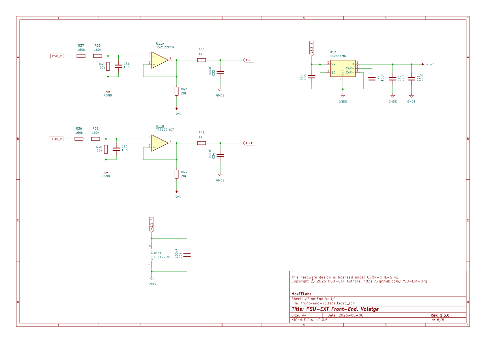
The revised design places a TSZ122 dual precision operational amplifier between the voltage dividers and the ADC. Each amplifier channel is a unity-gain follower. The divider sets the voltage ratio, and the buffer provides a low-impedance signal to the converter.
Measured voltage
      |
    160 kΩ
      |
    160 kΩ
      |
      +----> TSZ122 follower ----> 1 kΩ ----> ADS1115
      |                                      |
     20 kΩ                                 100 nF
      |                                      |
     GND                                    GND
A 10 nF capacitor also sits across each divider's 20 kΩ resistor. The buffer drives the 1 kΩ / 100 nF filter at the ADC input.
This gives the voltage channels an actively driven input, as the current channel already has. The aim is to preserve consistent voltage readings while changing the PGA range and ADC rate.
Getting the Buffer Close to Zero
The next experiment focused on the bottom of the measurement range. A voltage follower needs to follow its input down to ground. A rail-to-rail output specification still leaves a finite output swing limit that depends on loading.
In an initial MCP602 follower test, grounding the input produced about 3 mV at the output. With a 17:1 divider, that corresponds to 51 mV referred back to the measured input. For the new buffer circuit, operation close to ground deserved its own solution.
We added a resistor from each buffer output to a negative rail:
Divider ----> TSZ122 follower ----+----> ADC filter
                                 |
                               20 kΩ
                                 |
                         -3.3 V charge pump

TSZ122 supply pins: +3.3 V and GND
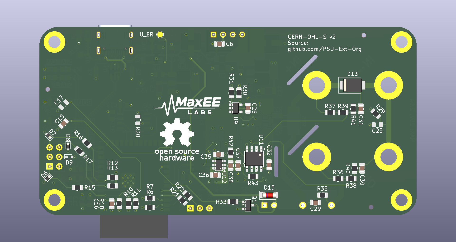
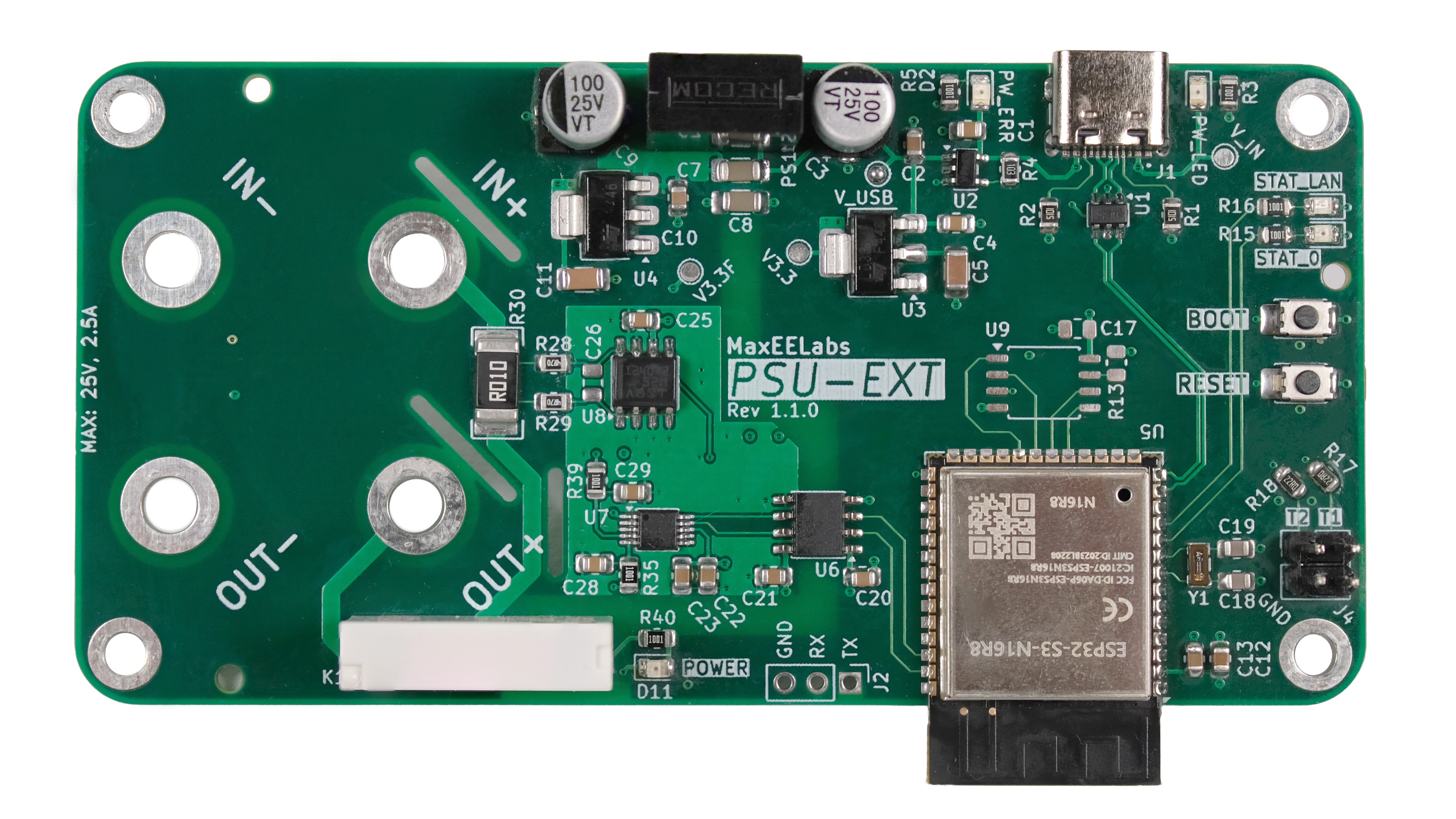
An LM2664 (U12 on the image below) charge pump generates the nominal -3.3 V rail. Each 20 kΩ resistor draws approximately 165 µA when the buffer output is near 0 V. This keeps the amplifier sourcing current as its output approaches ground.
![]()
The negative rail connects through the output resistors. The TSZ122's supply pins remain at ground and +3.3 V on the isolated measurement side.
Art Kay describes this technique in Texas Instruments' Single Supply Op Amp with True Drive to GND. The pull-down provides a current path to the negative supply, allowing the amplifier's lower output transistor to turn off near ground. It is a useful way to extend a single-supply buffer's operation toward zero.
The Dual-Supply Alternative
Another approach is to power the buffer from positive and negative rails, placing ground inside its output range. That would require suitable supply voltages for the selected amplifier.
The TSZ122 operates from a total supply voltage of 1.8 V to 5.5 V same as other modern precision opamps. Directly connecting it across +3.3 V and -3.3 V would apply 6.6 V. Regulated ±2.5 V or ±1.8 V rails would fit its operating range, but generating and regulating those rails would add components and board space.
For this revision, the output pull-down arrangement lets us retain the existing 3.3 V amplifier supply and use the charge pump for output bias.
![]()
Breadboard Results and the Next Boards
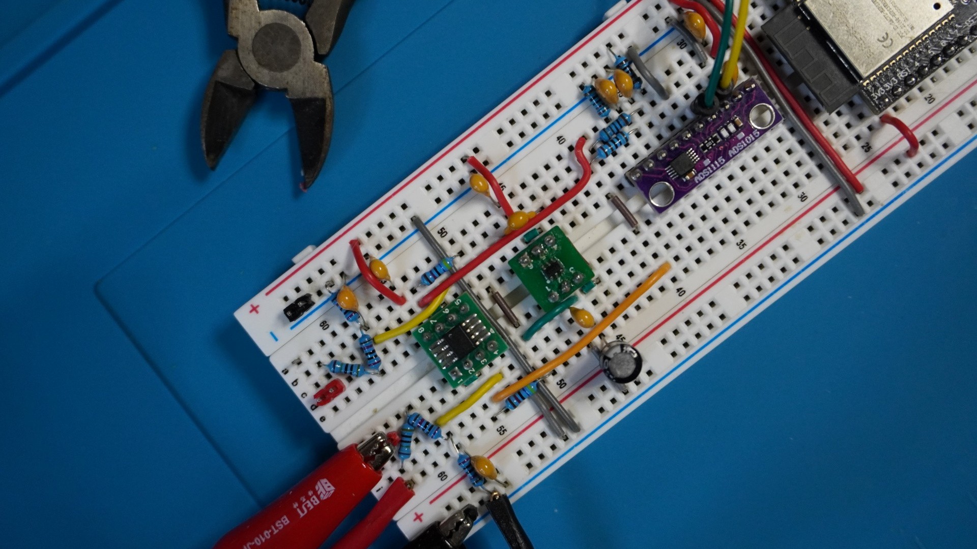
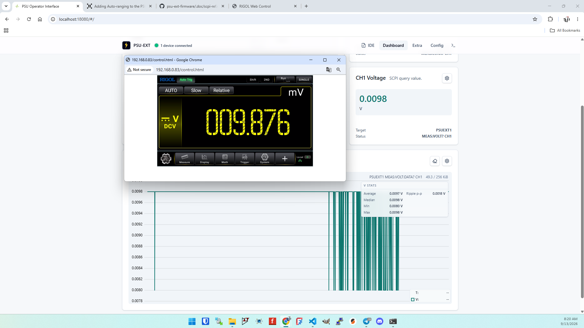
Breadboard tests with the TSZ122 and MCP602, using the charge pump and output pull-downs, have shown approximately 1 mV resolution in the 0–0.2 V measurement region. That is a good result for the new front end.
![]()
The revised boards are on order, and we are waiting for them to arrive. The new board's resolution is TBD. We will measure it on the assembled hardware, alongside voltage accuracy and behavior across the programmable ranges and rates. The breadboard result describes resolution; a new accuracy specification will come from those measurements.
The development started with a working fixed-PGA, fixed-ADC-rate design. Adding autoranging and programmable acquisition speed led us through the divider, the buffer, and the buffer's output stage near ground. The next step is to put that complete signal path through its measurements on the new boards.
If you like the article, please support us by following PSU-EXT on Crowd Supply. You'll receive more project updates and launch news.
-
One SCPI Standard, One Bridge, USB and TCP Under the Hood
09/06/2026 at 16:44 • 0 commentsPrerequisite
Getting a device connected and the PSU-EXT Dashboard open follows the Installation section of the psu-ext-software README.
Overview
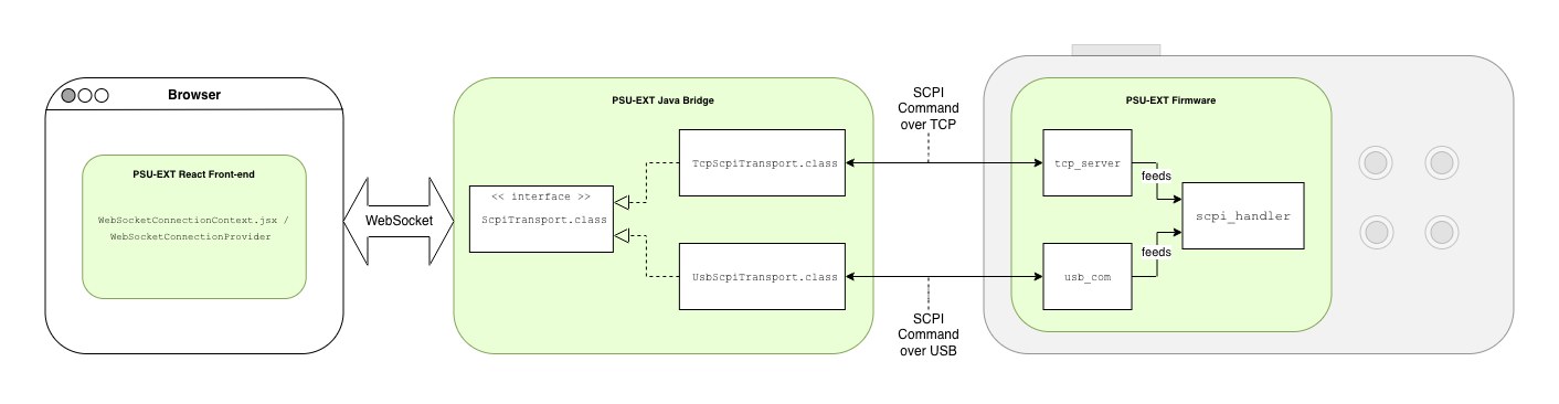
Our dashboard, backend, and firmware all speak SCPI, the standard ASCII command language for test-and-measurement instruments. Two transports and one WebSocket bridge carry that command language between browser and device — nothing here invents a protocol of its own.
That choice matters in practice. One shared command language means every dashboard widget and script talks to PSU-EXT the same way, regardless of how it's connected. Exposing that language over two transports instead of one means a USB-tethered setup on a workbench and a Wi-Fi-only deployment across the room run on identical firmware, with nothing to swap out between them.

One query, one bridge, two possible transports, one firmware dispatcher.
The stack behind it
Front-end ( psu-ext-software/psu-fe )
- Framework: React 18.3.1 + React Router 6.30.1, built with Vite 6.0.5
- Styling: Tailwind CSS 4.1.0 (via the @tailwindcss/vite plugin)
- Charting: uPlot 1.6.32 — the live telemetry chart widgets
- Icons: lucide-react
- Testing: Vitest 4.1.5 + Testing Library (React, jest-dom), jsdom
Back-end ( psu-ext-software/psu-be )
- Language/runtime: Java 25, Maven multi-module build (parent + BOM pattern)
- Framework: Spring Boot (version pinned via the psu-be-bom/parent POMs; spring-boot-maven-plugin 4.0.6)
- Transport-specific: spring-integration-ip (backs "TcpScpiTransport.class") and jSerialComm (backs "UsbScpiTransport.class")
- WebSocket: spring-boot-starter-websocket — backs "ScpiWebSocketHandler.class"
- Serialization: Jackson (jackson-databind, jackson-datatype-jsr310) - Testing: JUnit 5 + Mockito across all modules
SCPI: the command language, not the wire
SCPI (Standard Commands for Programmable Instruments) is an established, ASCII-text command-set standard for controlling test-and-measurement instruments. It's built on IEEE 488.2-1992, the message-exchange and common-command layer originally defined for GPIB (General Purpose Interface Bus) instruments under IEEE-488.1, and it grew up in the context of GPIB and VXIbus test gear. Its latest formal revision is commonly referenced as "SCPI-99."
The format is hierarchical and colon-separated: a command like "MEAS:VOLT?" addresses a "MEASURE" subsystem's "VOLTAGE" node. Commands defined by IEEE 488.2 itself — the ones every SCPI instrument shares regardless of what it measures — are prefixed with an asterisk, such as "*IDN?", "*RST", and "*CLS'. A trailing question mark on the header is what distinguishes a query, which expects a reply, from a plain command, which doesn't.
Crucially, the standard is transport-agnostic by design: it defines the command language, not the physical or electrical link it rides on.
PSU-EXT's own SCPI commands
Our command surface implements exactly one IEEE-488.2 common command:
*IDN?, which returns
PSU-EXT,ESP32-S3,0001,0.1.0and is handled before anything else, ahead of the per-family dispatch chain. Beyond that, everything is organized into eight command families:
System (`SYST`) "SYST:ERR?" returns "0,"No error";
"SYST:DATETIME" sets a runtime wall-clock mapping that isn't persisted across rebootsMeasure
(`MEAS`)"MEAS:VOLT? CH1" and "MEAS:CURR? CH1' read output voltage and current; "MEAS:VOLT:DATA? CH1" returns a binary block of stored history records. Calibration
(`CAL`)"CALibration:STARt VOLTage,CH0" opens a calibration transaction;
"CALibration:COMMit" validates the staged points and writes them to non-volatile storage.Output
(`OUTP`)"OUTP CH1,1" energizes the output relay (after clearing latched protection and checking the input-voltage condition);
"OUTP? CH1" reads the relay state back.Protection
(`OVP`/`OCP`)"OVP CH1,<value>" sets the over-voltage threshold;
"RESET:PROTect CH1" clears a latched protection tripTimer
(`TIMer`)"TIMer:ADD CH1,<id>,<seconds>,<0|1>" queues a delayed relay transition; "TIMer:STATus? CH1" reports whether that queue is idle, running, paused, or tripped. Trigger
(`TRIG`)"TRIG:CONF <trigger>,<HIGH|LOW>,<function>" maps a GPIO edge on one of the two physical trigger inputs to an action like turning the output on or starting a timer. WiFi
(`WIFI`)"WIFI:SSID <ssid>" and "WIFI:PASS <password>" store network credentials;
"WIFI:STATUS?" reports the live connection state.Some of that lines up with standard SCPI convention, some of it doesn't.
`SYST`, `MEAS`, `CAL`, `OUTP`, `OVP`,`OCP`all use subsystem names and query syntax that read the way a generic bench instrument's SCPI set would; the specific behavior underneath — CH0/CH1 channel semantics, the calibration stage/commit procedure, the pre-enable interlock on "OUTP", the exact threshold defaults on "OVP`/`OCP" — is ours.
WiFi configuration is the clearest example of something we added outright: there's no "WIFI" subsystem anywhere in the SCPI or IEEE-488.2 standard, so "WIFI:SSID", "WIFI:PASS", "WIFI:CLEAR", and "WIFI:STATUS?" have no standard analog to diverge from at all — we needed a way to configure the device's own network connection over the same command channel already used for everything else, so we added one.
Two transports
That whole command set — the standard-shaped families and the ones we added ourselves — reaches PSU-EXT over one of two physical connections: TCP or USB.
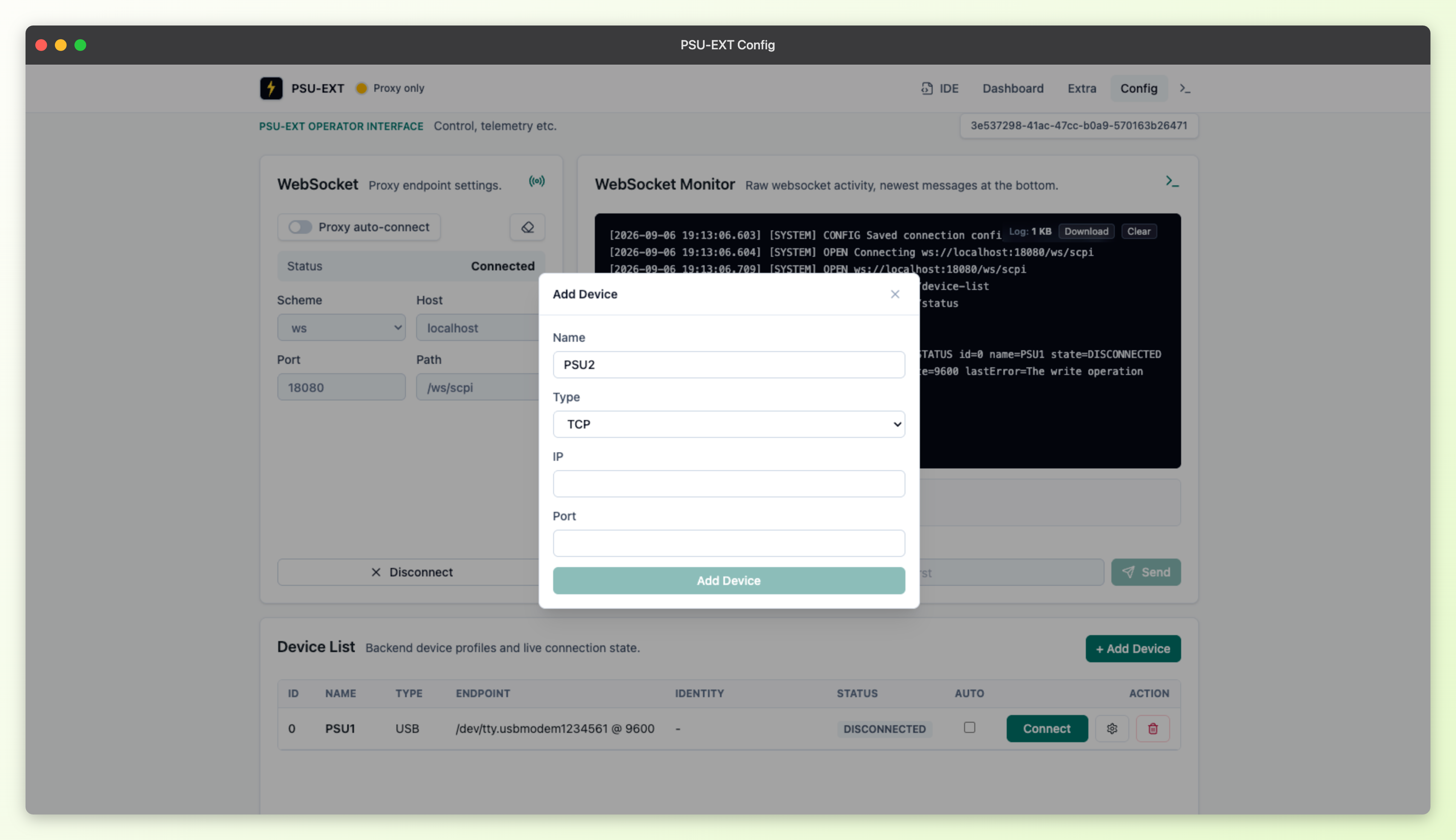
Adding a device starts from the dashboard's Config page: the "Device List" widget carries a "Add Device" button that opens a form offering the same TCP/USB choice. The device profile it creates is saved server-side rather than in the browser, so it's still there the next time anyone opens the dashboard, from any browser.
![]()
Our TCP transport's default target is "192.168.4.1:5025".
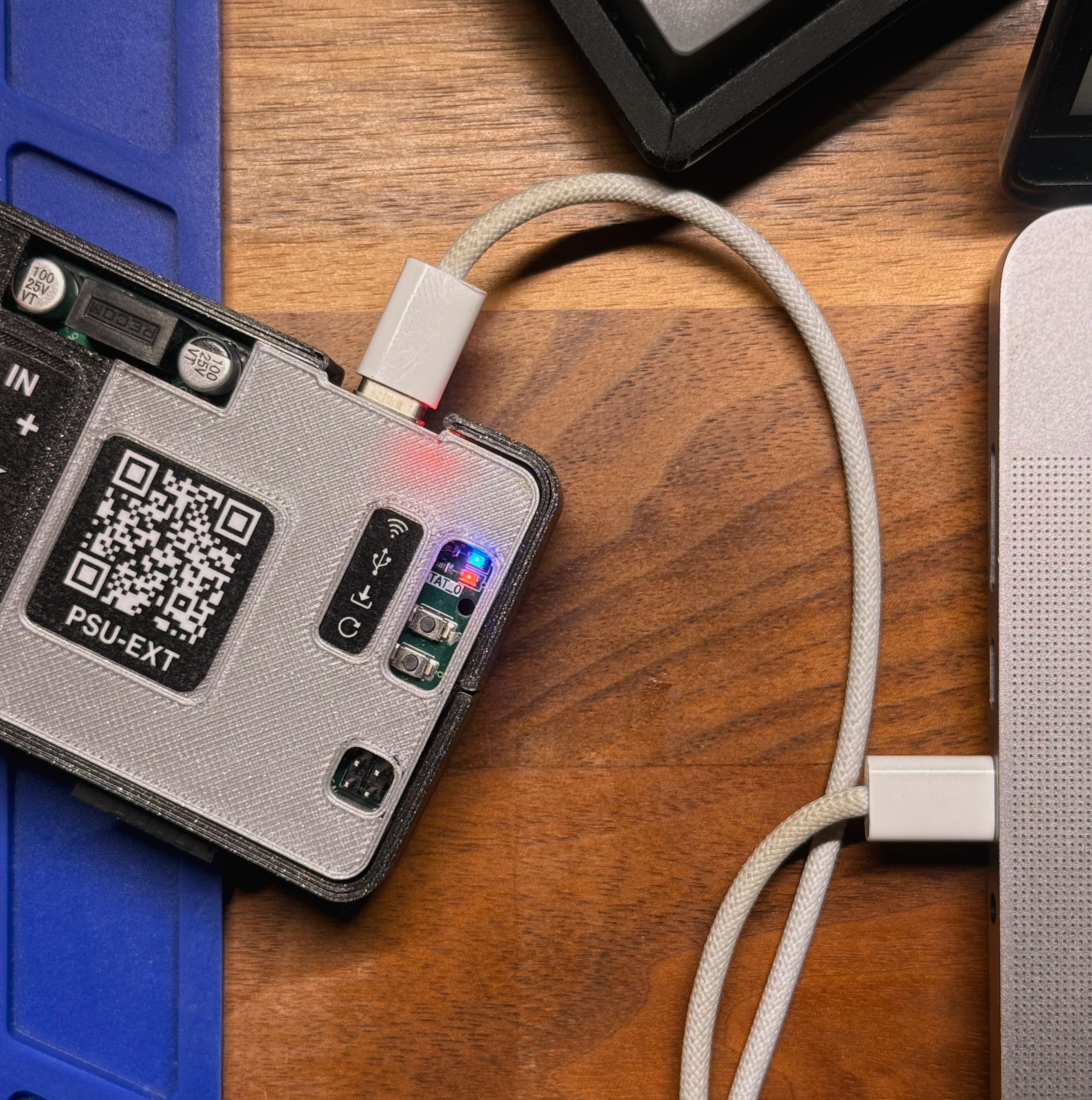
USB connects as a standard USB-CDC virtual COM port, so it shows up like any other serial device once plugged in.We also have two independent physical status LEDs, one per connection: a red LED on GPIO17 for USB status and a blue LED on GPIO18 for Wi-Fi status. Each lights solid once its connection is up. Wi-Fi additionally shows a slow breathing ramp while it's connecting; USB has no connecting state of its own, just connected, failed, or off. Both use the same fast-triple-blink-then-pause pattern to signal a failure, and both go dark when idle.

WiFi and USB Status LEDs
The Java bridge and WebSocket layer that normalizes both
The bridge is the piece of our backend written in Java that sits between the browser and whichever transport a device uses. It takes a command in from the browser's WebSocket connection, sends it out over TCP or USB, and relays whatever comes back straight to the browser.
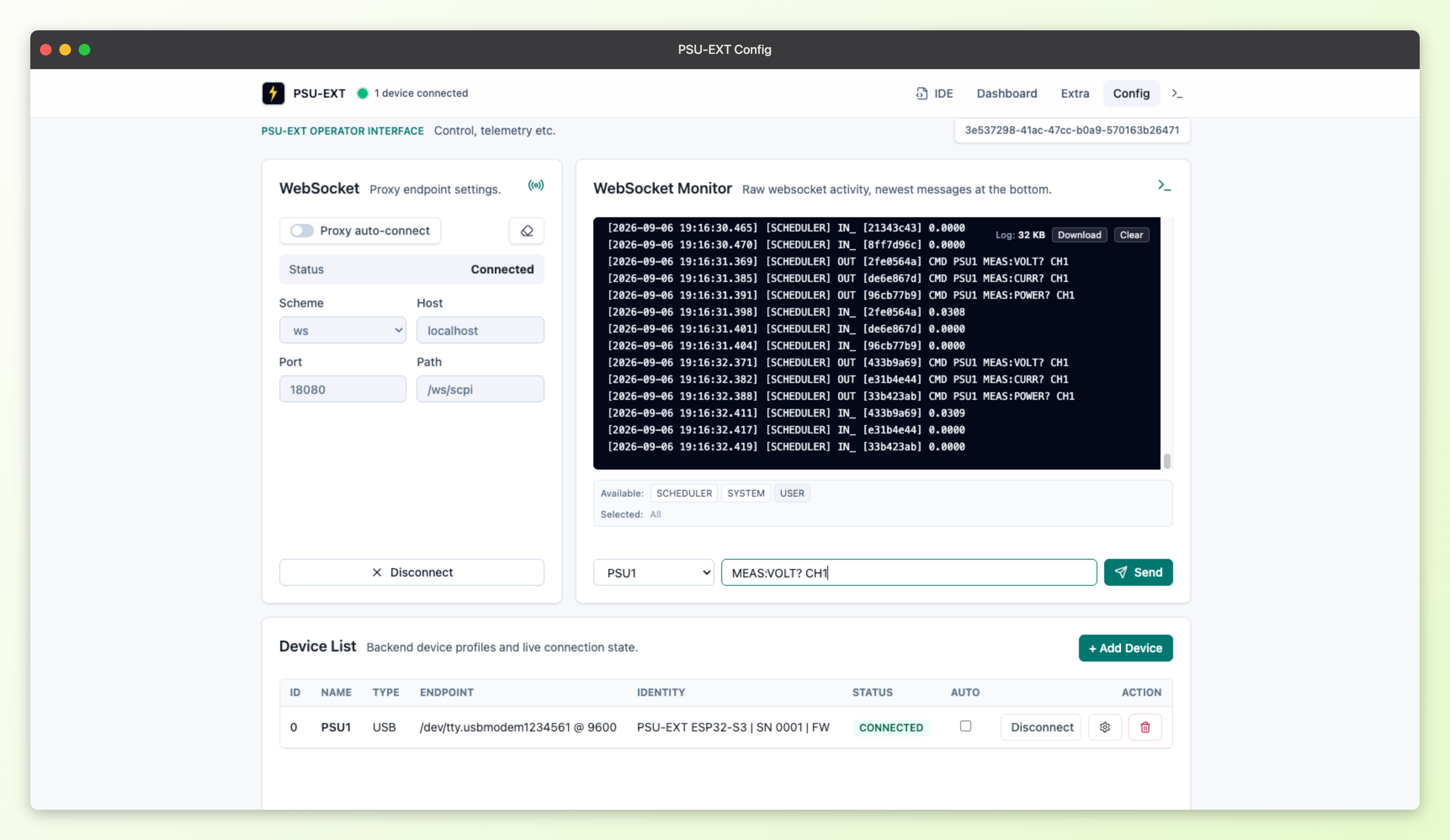
Both transports behave identically from the bridge's point of view — connect, send a command, wait for a reply if it's a query — so the bridge itself doesn't care which one a device is using. The dashboard's live telemetry charts poll frequently - each poll a "CMD <device> <query>" request — and running all of that over one persistent connection avoids the overhead of opening a fresh one for every query. The built-in SCPI console widget rides the same bridge: a command typed there goes out over the identical channel as the charts' polled queries.
![]()
Under the hood, that channel is a single WebSocket endpoint, "/ws/scpi", carrying a simple text envelope. Inbound frames use a "REQ <uuid> <payload>" format:
REQ 3f9c... /connect TCP-Bench-1
REQ 3f9c... MEAS:VOLT? CH1
Slash-prefixed commands (`/device-add`, `/device-list`, `/device-modify`, `/device-delete`, `/connect`, `/disconnect`, `/status`) handle device management; anything else is forwarded as raw SCPI text.
Outbound frames reply with
RES <uuid> <payload>for plain text and acknowledgements like
OK SENT`, or `BIN <uuid> <base64-scpi-block>for binary SCPI definite-length blocks such as the reply to "MEAS:VOLT:DATA?".
Firmware's own shared dispatcher underneath both transports
Our firmware mirrors the same split on the device side. Every incoming command, regardless of which link it arrived on, lands at:
scpi_handler_handle_command()It uppercases the command keyword and chains through handler families in order — system, measure, calibration, output, protection, timer, trigger, and WiFi — before falling back to
ERR,"Unknown command"Two components feed that one dispatcher.
- "usb_com" is a USB CDC ACM interface on TinyUSB, exposed as a virtual COM port and line-buffered until it sees a CR/LF.
- "tcp_server" is a raw TCP server on port 5025, with a listen backlog of one and a single active client socket.
Neither touches output, measurement, or protection logic on its own; both just hand the received line to the dispatcher.
Where this leaves us
That's the full path, end to end: one SCPI command surface, exposed over TCP or USB, unified by one WebSocket bridge for the browser, and landing on one shared dispatcher in firmware regardless of which link it came in on. Nothing here is aspirational — it's what's running on PSU-EXT today, and it's the foundation every dashboard widget and script in this project builds on.
Source links:
Follow Along on Crowd Supply
If you're interested in PSU-EXT, subscribe to our pre-launch page on Crowd Supply: crowdsupply.com/maxeelabs/psu-ext
-
Step Motor Current and Power Profiling
09/02/2026 at 04:50 • 0 commentsDriving a stepper motor is often one of the first practical electronics experiments. The 28BYJ-48 motor and its ULN2003 driver board are inexpensive, widely available, and simple to control from an Arduino. Paul Gallagher's 28BYJ-48 project in LittleArduinoProjects provides a useful introduction to the motor, the driver board, the coil sequence, and the required connections.
This article examines the same circuit from a power perspective. We use PSU-EXT to measure its current and power consumption in different operating modes, including holding with one or two energized coils and running the motor at different step rates.
Setup
![]()
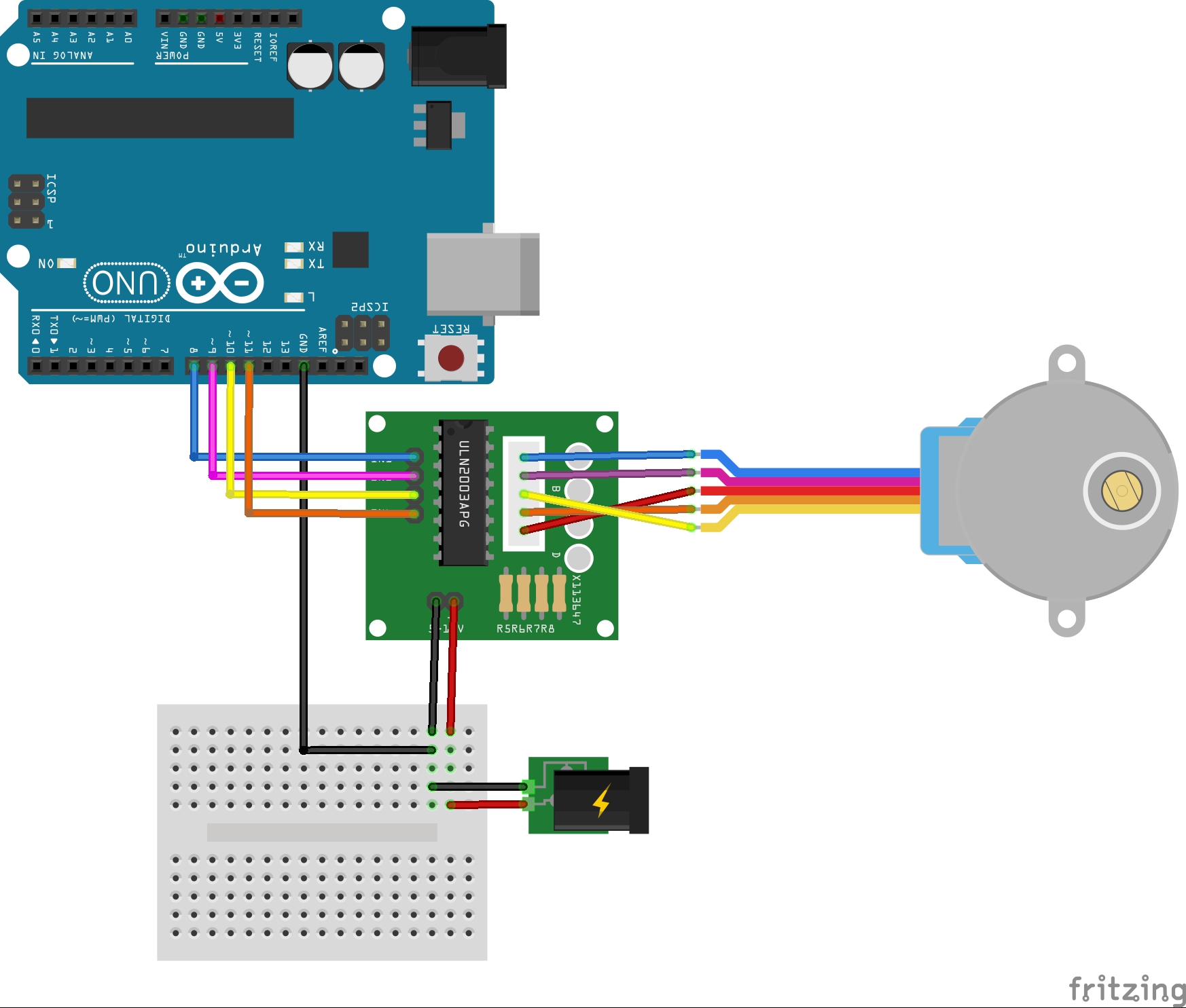
Figure 1. Basic 28BYJ-48 and ULN2003 wiring. Copyright © Paul Gallagher. Image from LittleArduinoProjects, used under the MIT License
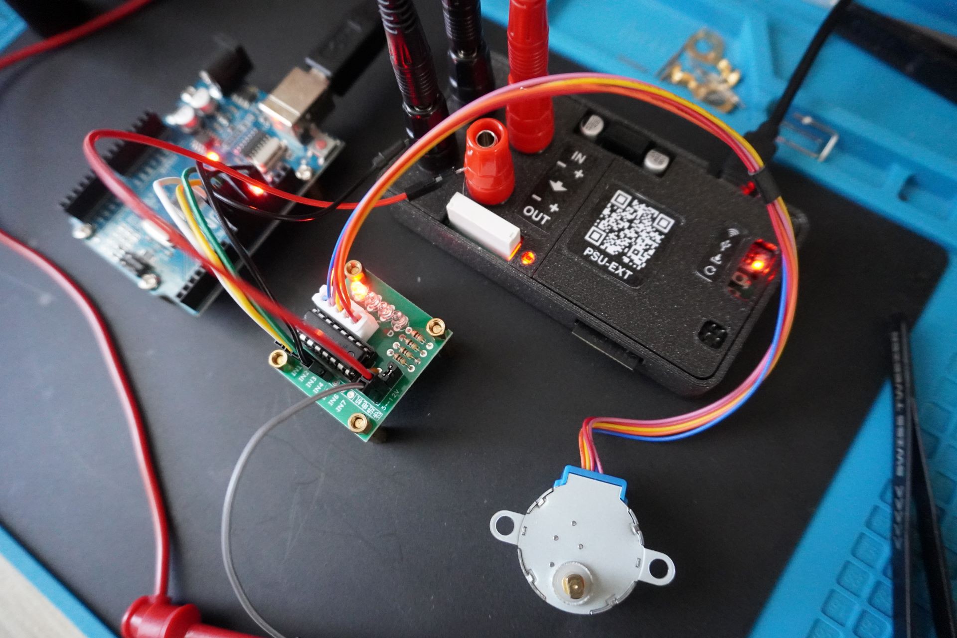
The Arduino ground is connected to the ULN2003 module ground, as shown in Figure 1. The Arduino and PSU-EXT are each powered over USB. The motor receives 5 V from the bench power supply through PSU-EXT.
![]()
A Rigol DM858E digital multimeter is connected in series with the motor circuit. It provides an independent current measurement for comparison with the PSU-EXT reading. The complete current path is the bench power supply, PSU-EXT, ULN2003 driver, 28BYJ-48 motor, DM858E current input, PSU-EXT return, and bench power supply return.
Arduino Control Sketch
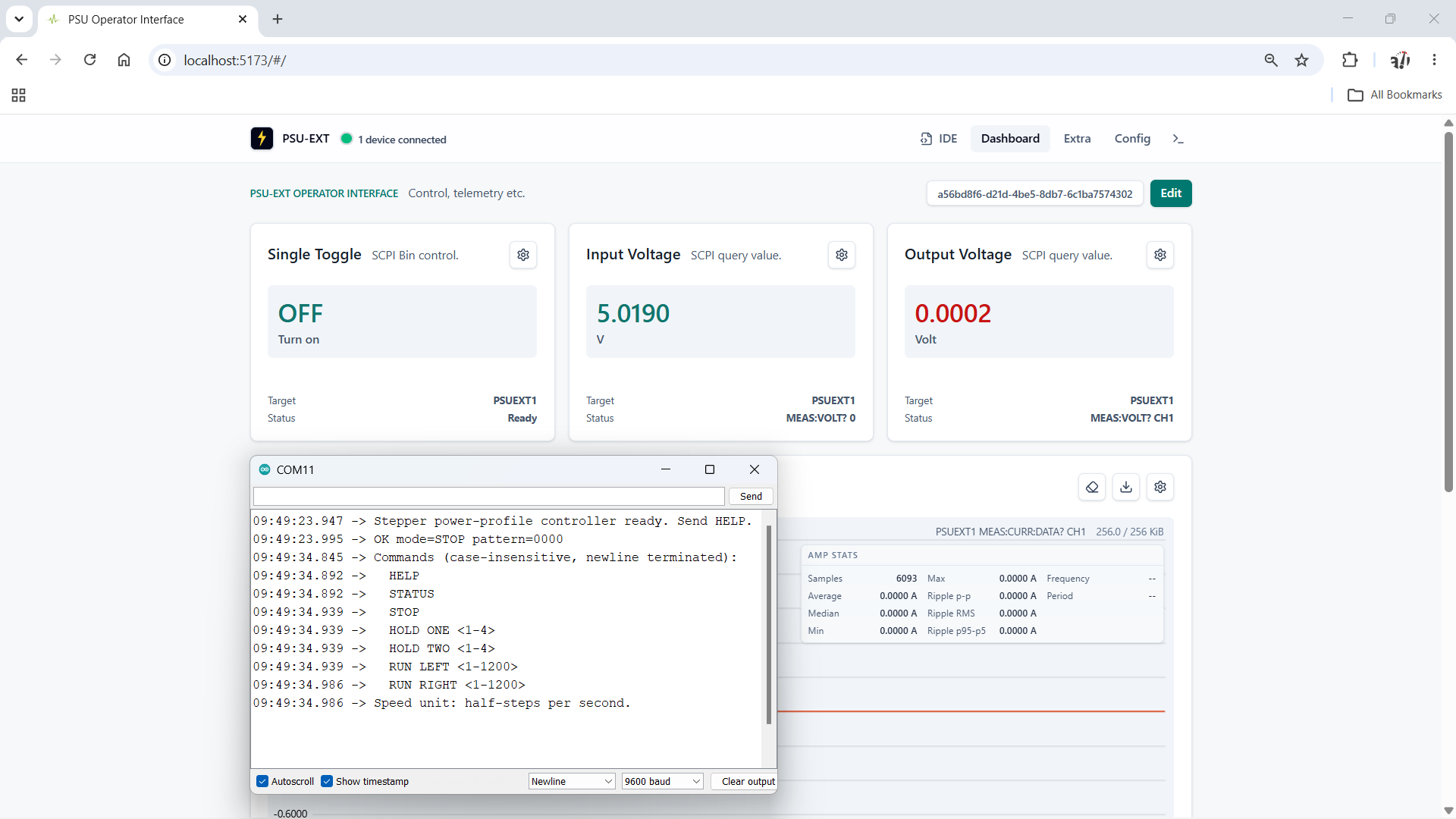
The Arduino sketch drives the motor with an eight-state half-step sequence and accepts newline-terminated commands over a 9600-baud serial connection. This lets us select a repeatable coil state or running speed while recording the electrical measurements.
Command Function HELP Lists the available commands. STATUS Reports the current mode, coil pattern, direction, and speed. STOP De-energizes all four driver inputs. HOLD ONE <1-4> Holds one of four positions with one coil energized. HOLD TWO <1-4> Holds one of four positions with two adjacent coils energized. RUN LEFT <1-1200> Advances through the sequence at 1 to 1200 half-steps per second. RUN RIGHT <1-1200> Traverses the sequence in reverse at 1 to 1200 half-steps per second. The running range starts at one half-step per second because zero represents the stopped state and cannot be used to calculate a step interval. The upper limit of 1200 half-steps per second was selected as an experimental ceiling. A common 5 V 28BYJ-48 datasheet specifies a no-load starting frequency above 600 Hz and a no-load running frequency above 1000 Hz. Extending the test range to 1200 half-steps per second lets us examine the motor near and beyond that documented region. It is not a guaranteed operating speed, and the sketch applies the requested speed without an acceleration ramp. The observed shaft direction depends on the motor wiring and the side from which it is viewed.
![]()
Testing Hold Modes: One or Two Coils
The sketch provides one-coil and two-coil hold modes. Each mode has four selectable electrical positions. These numbers identify positions in the drive sequence, not absolute positions of the geared output shaft.
Command IN1 IN2 IN3 IN4 Energized coils HOLD ONE 1 1 0 0 0 1 HOLD ONE 2 0 1 0 0 1 HOLD ONE 3 0 0 1 0 1 HOLD ONE 4 0 0 0 1 1 HOLD TWO 1 1 1 0 0 2 HOLD TWO 2 0 1 1 0 2 HOLD TWO 3 0 0 1 1 2 HOLD TWO 4 1 0 0 1 2 One-coil hold provides the lower-power reference. Two-coil hold energizes two windings at the same time and should draw more current while providing greater holding torque. Measuring all four positions also shows any differences between the individual windings and driver channels.
HOLD ONE 1
The
HOLD ONE 1command keeps the first ULN2003 input active and energizes one motor winding continuously. The motor remains stationary while the energized winding produces holding torque.
![]()
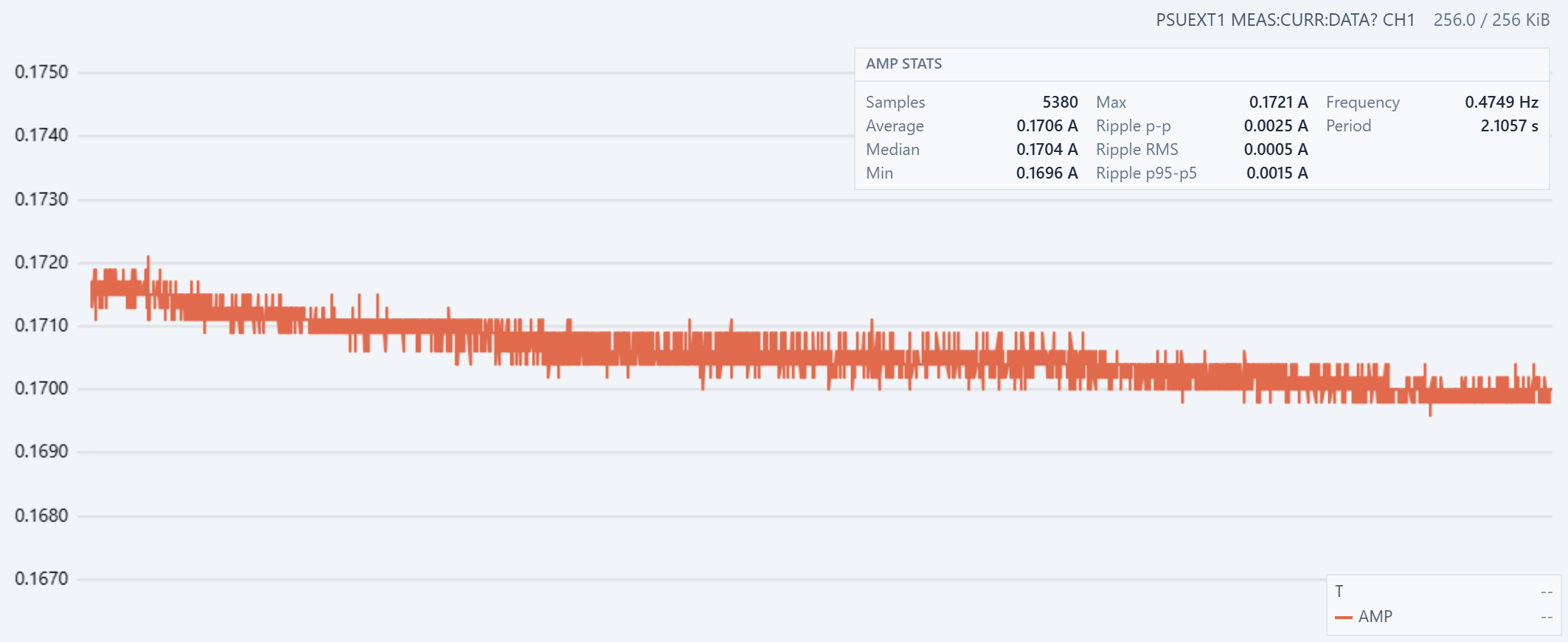
Figure 2. PSU-EXT current measurement during HOLD ONE 1. The recorded minimum is 0.1696 A, the maximum is 0.1721 A, and the average is 0.1706 A.
The full recorded span is 2.5 mA, or about 1.45% of the maximum. The sustained current level falls by less than this because the minimum and maximum include short spikes. The downward trend is consistent with thermal settling. Current heats the energized copper winding, and copper resistance increases with temperature. The higher resistance reduces the current from a constant-voltage supply. The ULN2003 output transistor also warms up, which can increase its voltage drop and reduce the voltage available to the winding.
The current stabilizes when the heat generated in the winding and driver is balanced by the heat transferred to the surrounding air and hardware.
The HOLD ONE 2 to HOLD ONE 4 measurements show no substantial difference from HOLD ONE 1, so their charts are not repeated here. Within the resolution and variation of this test, these windings and ULN2003 channels have similar current profiles.
HOLD TWO 1
The
HOLD TWO 1command activates IN1 and IN2, energizing two adjacent motor windings while the shaft remains stationary.
![]()
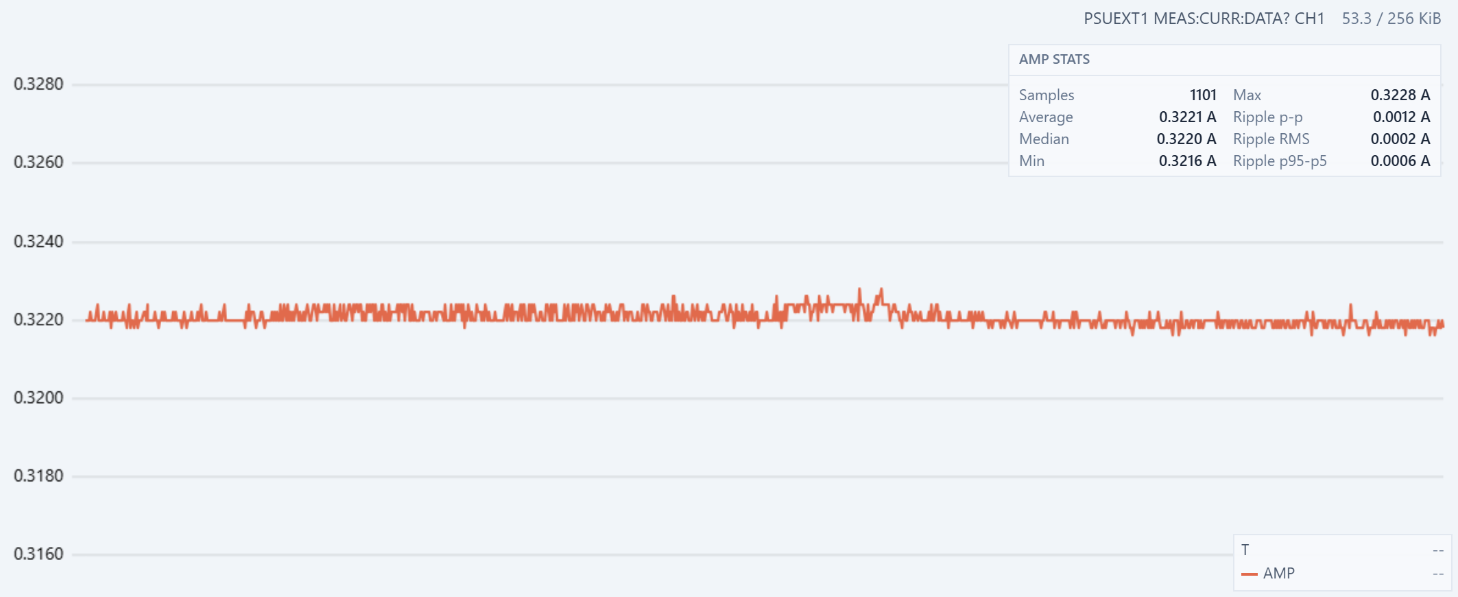
Figure 3. PSU-EXT current measurement during HOLD TWO 1. The average is 0.3221 A, the minimum is 0.3216 A, and the maximum is 0.3228 A.
The two-coil average is 0.1515 A higher than the 0.1706 A measured during HOLD ONE 1, an increase of about 88.8%. It is close to, but not exactly, twice the one-coil current. Shared wiring and return-path resistance, driver voltage drops, and small differences between windings and ULN2003 channels can all reduce the current from the ideal doubled value.
The trace is stable around 0.322 A. Its total recorded span is only 1.2 mA, or about 0.37% of the average. This level also agrees with the upper current plateau observed when the running half-step sequence energizes two coils.
Testing Run Modes at Minimum and Maximum Speed
RUN LEFT 1
![]()
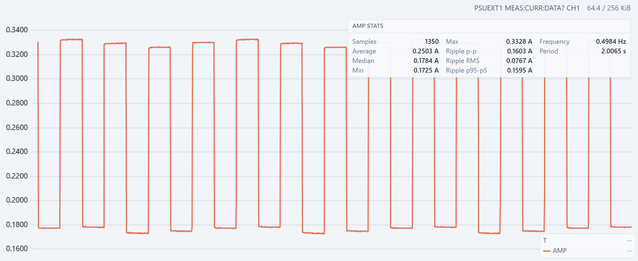
Figure 4. Current during RUN LEFT 1. PSU-EXT reports a minimum of 0.1725 A, a maximum of 0.3328 A, an average of 0.2503 A, and a waveform frequency of 0.4984 Hz.
At one half-step per second, each state lasts for one second. The half-step sequence alternates between one energized coil and two energized coils. The current therefore alternates between approximately 0.175 A and 0.330 A. The same coil-count state returns every two steps, giving an expected current-magnitude period of two seconds, or 0.5 Hz. The measured 0.4984 Hz agrees with this sequence timing.
The high and low plateaus vary slightly as the sketch moves through the four windings and ULN2003 channels. This is consistent with the small channel differences observed in the hold tests. The average is also close to the midpoint between the one-coil and two-coil levels because both states have the same duration.
RUN LEFT 1200
![]()
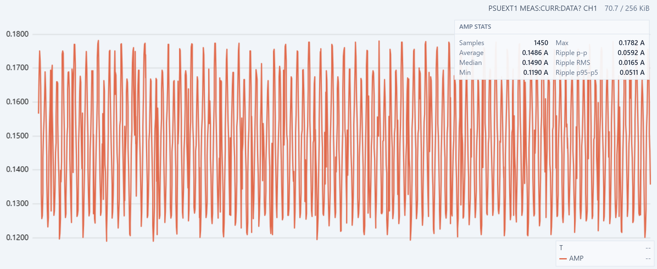
Figure 5. Sampled current during RUN LEFT 1200.
At 1200 half-steps per second, each state lasts about 833 µs. The sequence still alternates between one-coil and two-coil states, so its current-magnitude component is expected at 600 Hz. The complete eight-state electrical sequence repeats at 150 Hz. These changes are much faster than the plotted samples (100 Hz) can resolve.
The sample points are distributed evenly across the captured current range, and the sampled pattern repeats with consistent spacing. This shows that the acquisition is observing a stable periodic process and is not dominated by a few isolated spikes. However, the connected points represent samples taken at different phases of the switching cycle. The apparent cycles are a sampled pattern, not a complete reconstruction of the underlying 600 Hz current waveform or its true cycle time.
The reported average is about 0.15 A, compared with 0.2503 A at one half-step per second, a reduction of about 40%. The motor windings are inductive, so their current cannot reach the steady one-coil or two-coil level during an 833 µs state. Back electromotive force from a rotating motor can reduce it further. However, this current trace alone does not prove that the rotor remained synchronized with the commanded 1200 half-steps per second
![]()
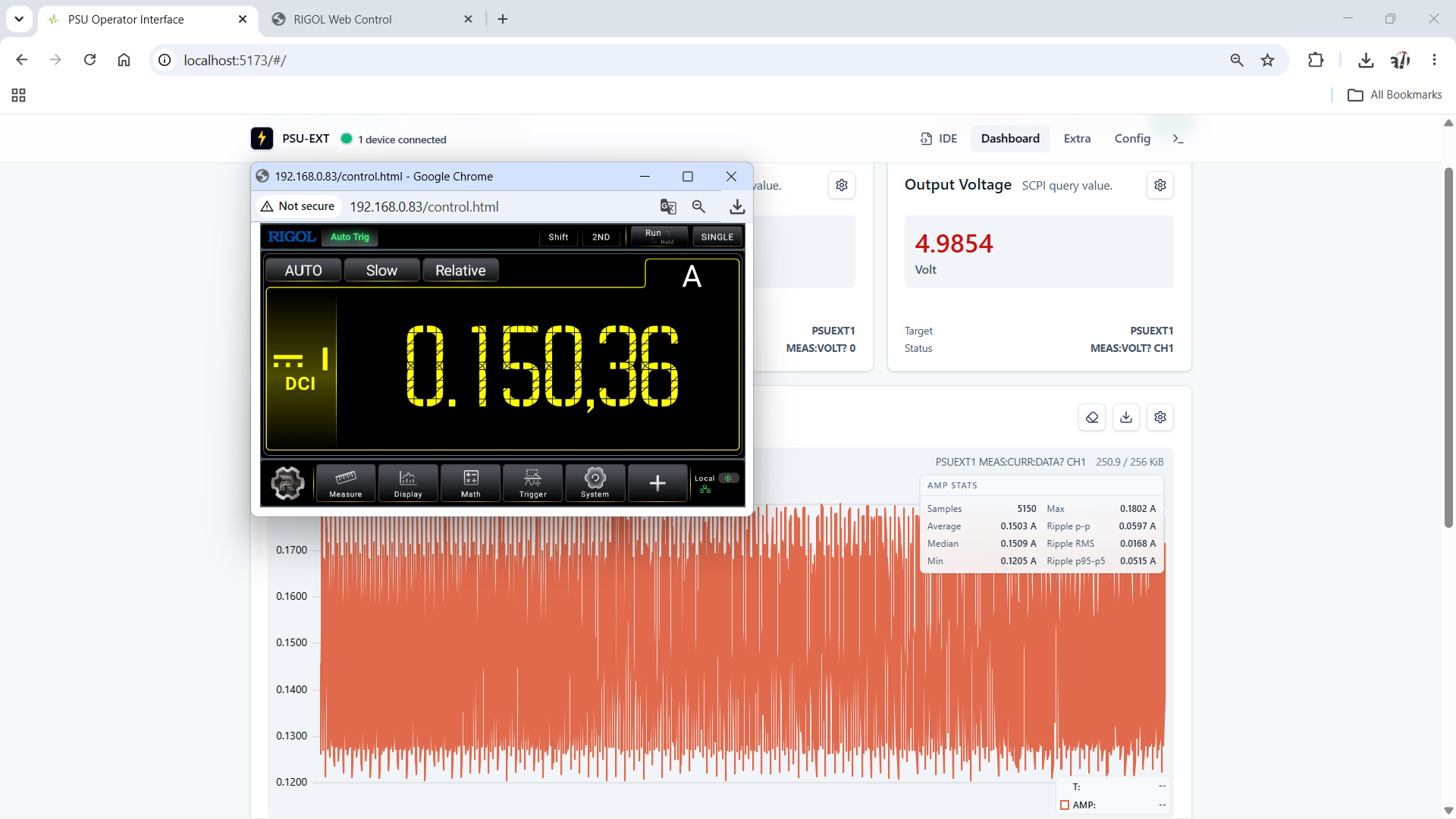
Figure 6. Independent current comparison during RUN LEFT 1200. PSU-EXT reports a 0.1503 A average over 5150 samples, while the Rigol DM858E reads 0.15036 A.
The displayed values differ by 0.00006 A, or 0.06 mA, which is about 0.04%. This close agreement shows why the limited waveform resolution does not make the measurement useless. The samples cover many switching cycles and are distributed across different phases rather than concentrated around one part of the cycle. They therefore produce a representative average even though they do not reconstruct each current pulse.
The independent DM858E result supports using the PSU-EXT capture to compare operating modes, estimate average power, observe thermal drift, and detect larger changes in operating state.
Transition From RUN LEFT 50 to RUN LEFT 1200
![]()
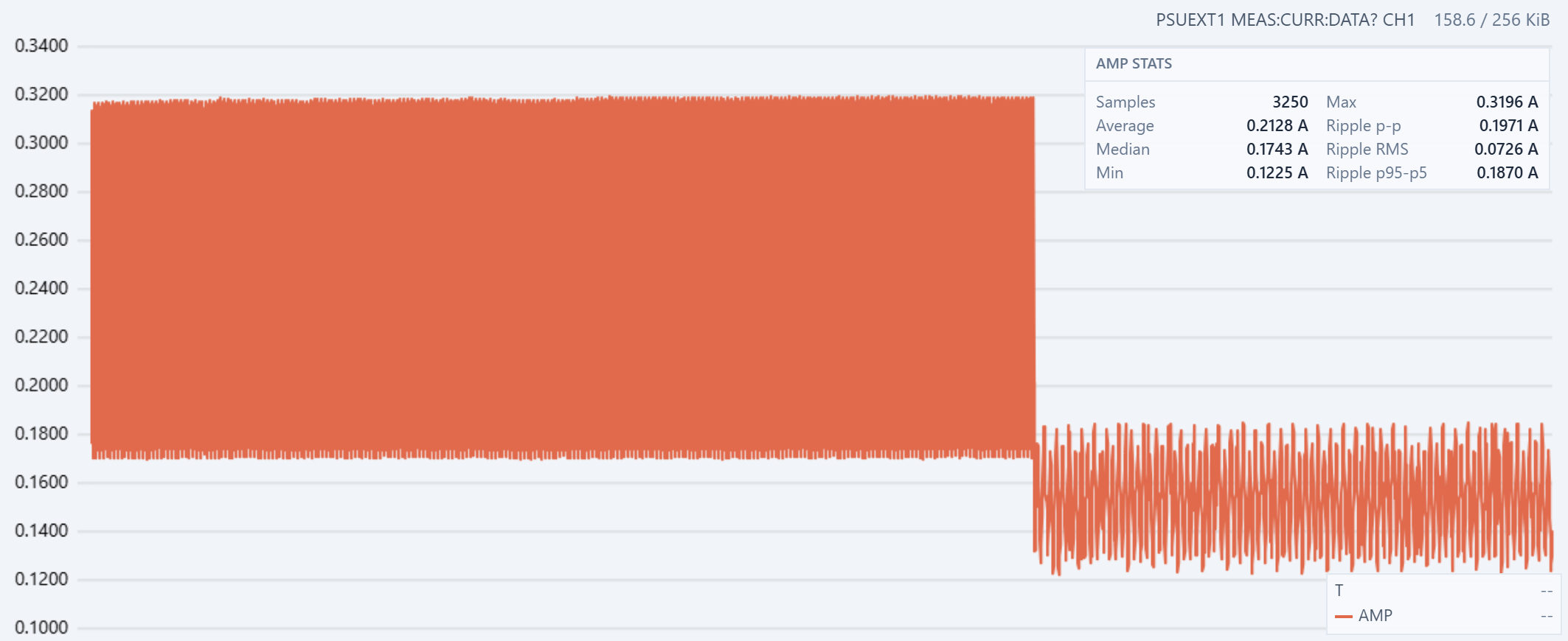
Figure 7. Current-envelope change when the command switches from RUN LEFT 50 to RUN LEFT 1200.
At 50 half-steps per second, each drive state lasts 20 ms. This gives the energized winding current time to approach the one-coil and two-coil levels seen in the slower tests. The left side of Figure 7 spans approximately 0.169 A to 0.320 A, an envelope width of about 0.151 A.
The command then changes directly to 1200 half-steps per second. Each state is now about 833 µs, which is 24 times shorter. The current envelope drops immediately to approximately 0.123 A to 0.184 A. Its midpoint falls by about 37%, and its width contracts from about 0.151 A to 0.061 A.
Winding inductance limits how quickly current can rise. At 1200 half-steps per second, the drive moves to the next state before the active winding currents can approach their steady values. If the rotor accelerates with the command, the higher back electromotive force also opposes the applied voltage and reduces current. These effects lower both edges of the envelope and reduce the difference between the one-coil and two-coil states.
The sharp boundary shows that the electrical load responds immediately to the speed command. After the transition, the lower current envelope remains stable, with no visible long settling period.
Full-Speed Direction Reversal
![]()
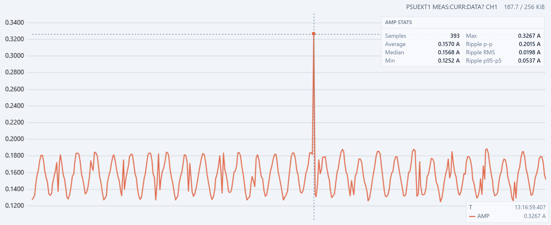
Figure 8. Current during an immediate change from RUN LEFT 1200 to RUN RIGHT 1200. The reversal produces a measured peak of 0.3267 A.
The current envelopes before and after the command are similar. Direction alone therefore has little effect on the steady high-speed current in this test. The capture average is 0.1570 A, while the reversal reaches 0.3267 A. The transient is about 2.1 times the average current and approaches the two-coil current seen at low speed.
The electrical sequence reverses immediately, but the rotor and gearbox cannot reverse their motion instantly. Rotor inertia keeps the motor moving in the original direction while the reversed magnetic field applies braking torque. During this brief braking and re-acceleration interval, the relationship between winding current, rotor position, and back electromotive force changes sharply. The resulting transient allows the supply current to rise well above the normal 1200-half-step-per-second envelope.
This is a reason to avoid an immediate direction change in normal motion control. A controlled profile should decelerate the motor, reverse at or near zero speed, and then accelerate in the opposite direction. That reduces current transients, mechanical shock, and the risk of losing steps.
Conclusion
This evaluation produced one counterintuitive result and one intuitive result. The counterintuitive result is that a higher commanded step rate draws less average current. The measured average falls from about 0.250 A at one half-step per second to about 0.150 A at 1200 half-steps per second. At high speed, each drive state is too short for the winding current to reach its steady value. Winding inductance limits the current rise, and back electromotive force can reduce it further. This lower current does not imply higher efficiency or greater mechanical output. It also means a smaller torque margin.
The intuitive result is that an immediate direction change at full speed produces a current spike. The rotor must first lose its existing motion and then accelerate in the opposite direction. The reversal reaches 0.3267 A, compared with an average of 0.1570 A during the surrounding high-speed operation. A controlled deceleration and acceleration profile would reduce this transient.
The captured power profile closely follows the current profile. The WEP305D linear bench power supply used in this experiment shows minimal voltage drop while the load remains below 0.5 A. With the supply voltage nearly constant, power is approximately a scaled version of current because
P = V × I
The current reduction at high speed and the reversal spike therefore appear in the power data with the same shape and relative size.
In this experiment PSU-EXT adds the time dimension to measurements from a conventional bench supply. While Rigol multimeter confirmed the average current, PSU-EXT showed how the load changed during warm-up, speed changes, and direction reversal. Recording voltage, current, and power together provides a more complete view of device behavior than a single power supply front-panel reading.
In the future we might to introduce an Afterburner acquisition mode for faster measurements. The target is about 400 measurements per second from one selected analog-to-digital converter (ADC) channel, either voltage or current, while the other channel remains inactive. This planned mode would provide more detail for short events such as the direction-reversal transient.
If you like the article, pleaser follow current project and PSU-EXT on Crowd Supply for further project updates.
-
A Tour of the PSU-EXT Dashboard
08/30/2026 at 17:09 • 0 commentsPrerequisite
Getting a device connected and the PSU-EXT Dashboard open follows the Installation section of the psu-ext-software README.
The Tour
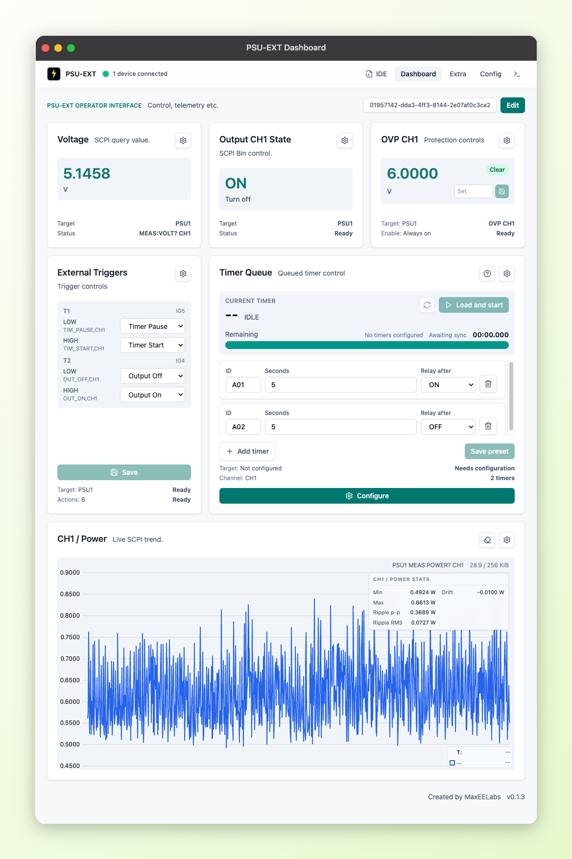
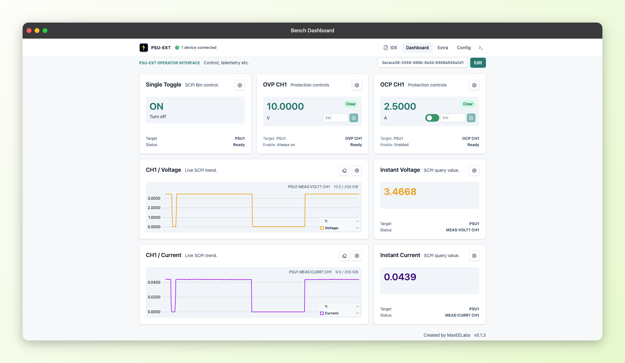
From there, here's where the dashboard itself stands today: a three-column grid built from a catalog of six widget types:
- Single Value (displays a live SCPI reading);
- Single Toggle (switches something on or off using SCPI commands);
- Protection Control (watches a threshold and flags whether it's tripped);
- External Triggers (hardware input pins to SCPI actions);
- Timer Queue (runs a queue of timed relay actions);
- Chart (plots SCPI query over time)
![]()
PSU-EXT Dashboard WIth All Types of Widgets
Getting the Grid Ready to Look Around
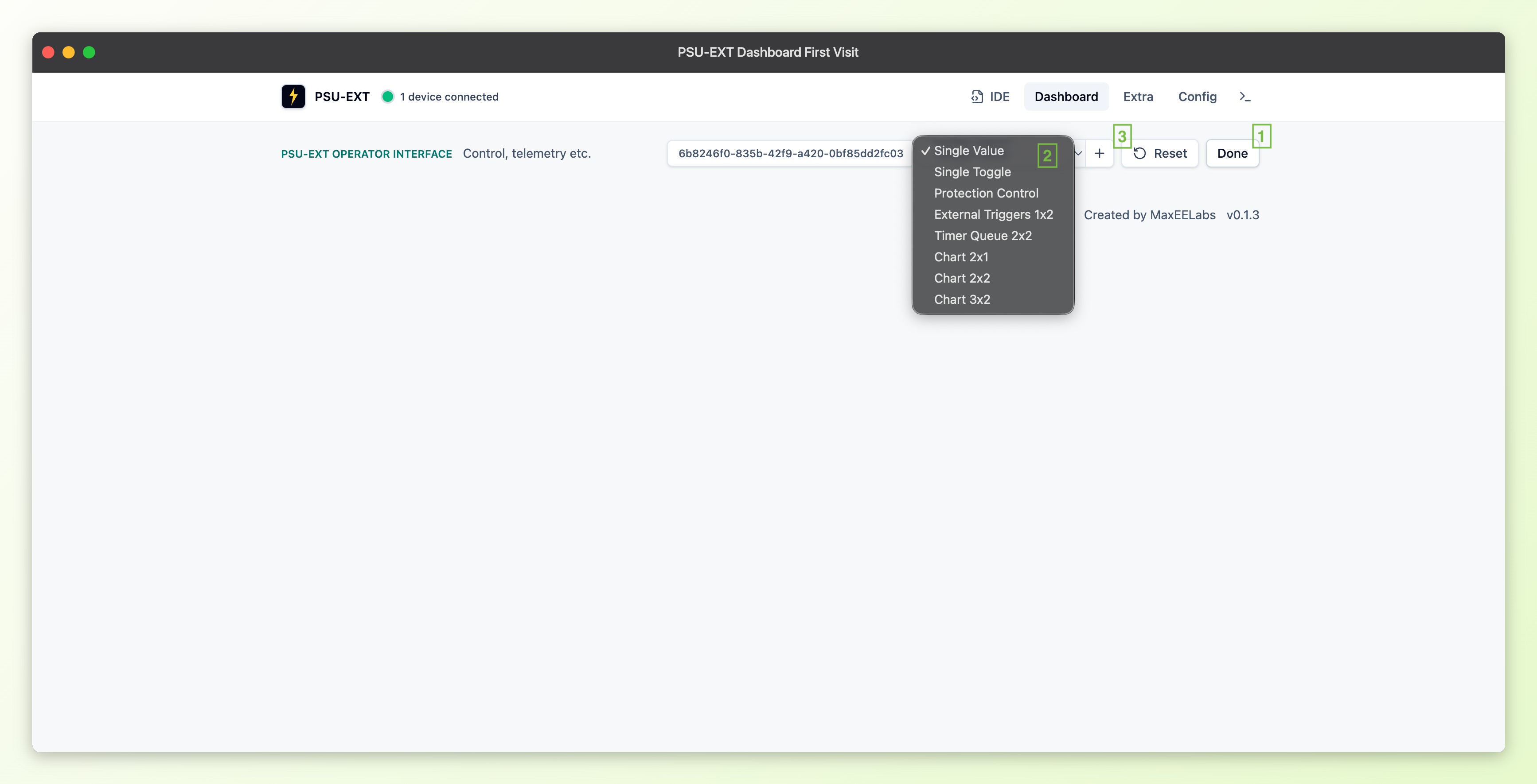
A toolbar "Edit"/"Done" (1) button unlocks dragging, deleting, and adding widgets. The Add widget catalog (2) lists eight entries mapped to the six widget types (three of those eight are the chart's fixed sizes). "Reset" (3) restores the default layout
Whatever layout you build persists locally in the browser.
![]()
PSU-EXT Dashboard First Visit
One fact applies to every widget type before we tour them individually: each widget picks its own target device independently, so a single dashboard isn't locked to one PSU-EXT unit. You can mix cards pointed at different connected devices on the same grid.
Single Value and Single Toggle: The Two Simplest Widgets
Single Value and Single Toggle are the two simplest widgets on the grid, both sized 1x1.
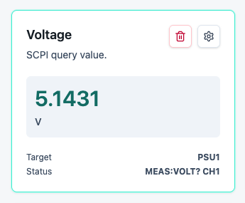
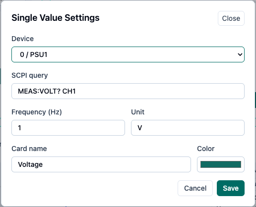
Single Value is a read-only display of one cached SCPI query result: a number plus a unit label, for example "5.1431 / V".

Single Value Widget

Single Value Widget Settings
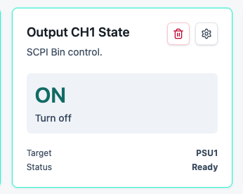
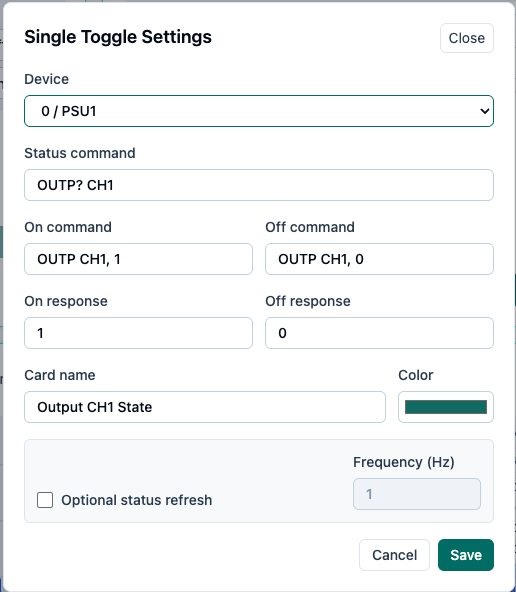
Single Toggle is a button that turns something ON or OFF — enabling a channel's output, say — and shows which state it's currently in: it checks a SCPI status query to know whether the thing it controls is ON or OFF right now, and clicking it sends one SCPI command for ON and a different one for OFF.

Single Toggle Widget

Single Toggle Widget Settings
Protection Control
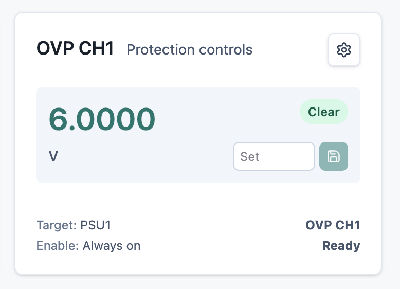
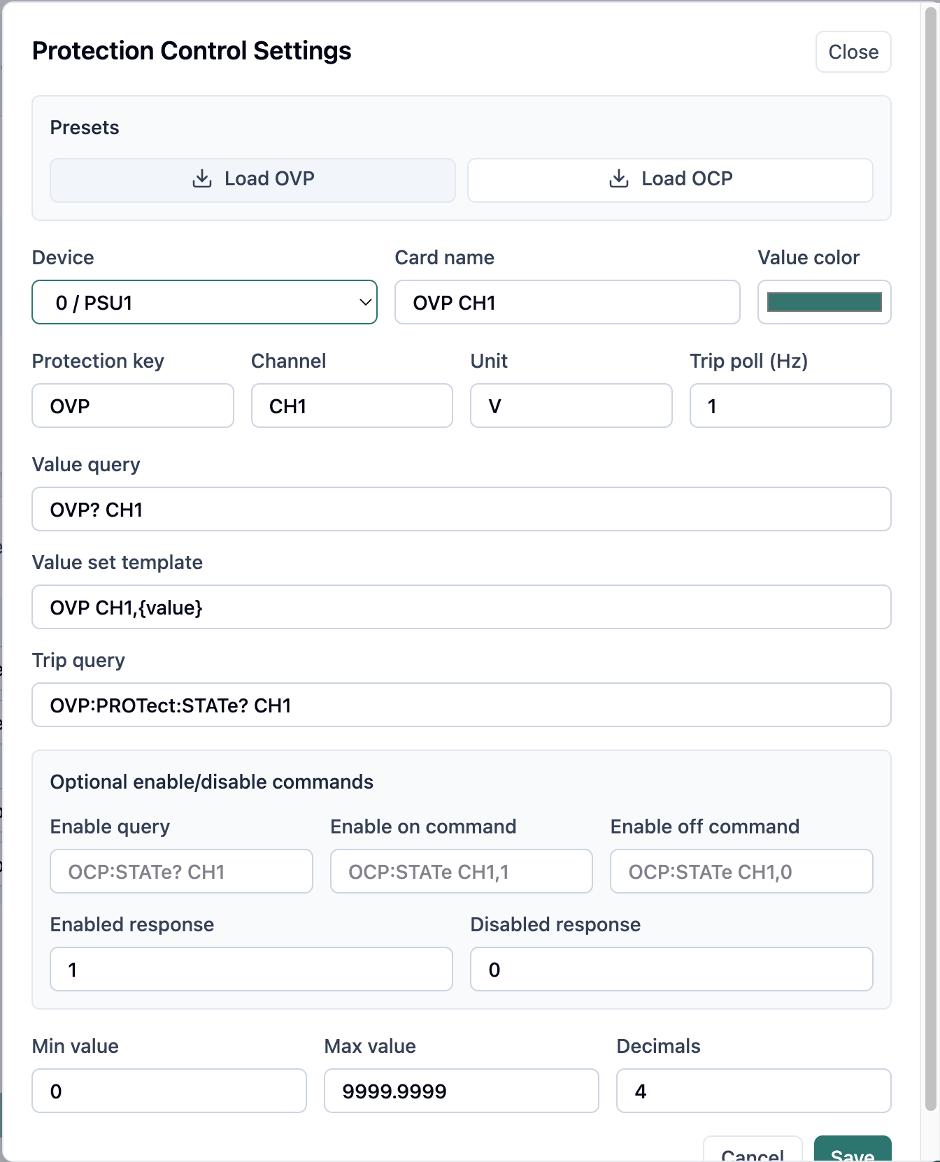
Protection Control is a 1x1 widget for one threshold — a voltage or current limit, set in an editable field with a Save button next to it. The PSU-EXT decides when that threshold's been crossed; the widget polls the device's reported trip state and shows it as a Tripped/Clear badge.
Each widget instance is single-purpose: it's tied to one protection key and one SCPI query/set-command pair. Watching OVP (over-voltage protection) and OCP (over-current protection) on the same channel takes two separate widget instances on the grid, not one widget with two thresholds.

Protection Control Widget

Protection Control Widget Settings
External Triggers: Reading Hardware Inputs Into SCPI Actions
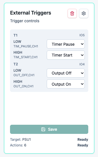
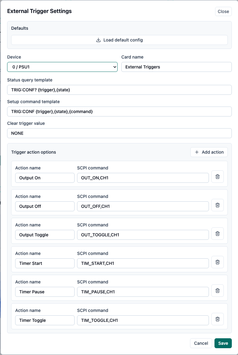
External Triggers is a 1x2 widget that reads two physical trigger inputs placed on PSU-EXT device — T1 on IO5 and T2 on IO4 — into SCPI actions. Each input has a LOW state slot and a HIGH state slot, four slots total, and each slot picks an action from a configurable list (defaults include Output On/Off/Toggle and Timer Start/Pause/Toggle) or None.
On the board itself, T1 and T2 are broken out at connector J4: a 4-pin (2x2), 2.54 mm-pitch header, silkscreened "T1" and "T2," so the two inputs are easy to find by eye.

External Trigger Widget

External Trigger Widget Settings
Timer Queue: An Ordered List of Timed Actions
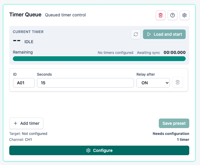
Timer Queue is a 2x2 widget that lets you queue up to ten timed relay actions in sequence, so you can cycle an output on and off over a schedule without writing a script. The code caps it at:
MAX_TIMERS = 10
The widget's config is hardcoded to CH1, so every timer in the queue acts on CH1's output relay — the same relay that Single Toggle's "CH1 Output" example switches. Each timer carries an ID of up to three characters, a duration in seconds, and a relay-after setting of ON or OFF: once that timer's duration counts down, CH1's output relay switches to whichever of those two states the timer was set to.
A timer must be saved as a preset and loaded onto the device before Load-and-start actually runs it — the widget makes that explicit, showing "Preset not loaded" until you've loaded it, then "Loaded on device" once it is.

Timer Queue Widget
Chart: Trends Over Time, in Three Fixed Sizes
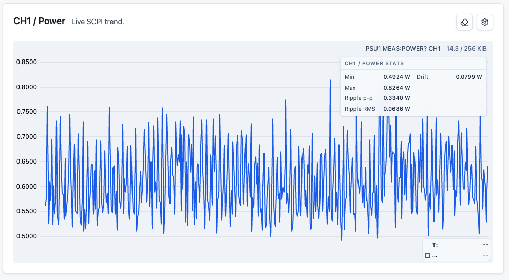
Chart comes in three fixed sizes — 2x1, 2x2, and 3x2.
Each chart plots one or more SCPI query series over time, and each series carries its own device, query, and line color.
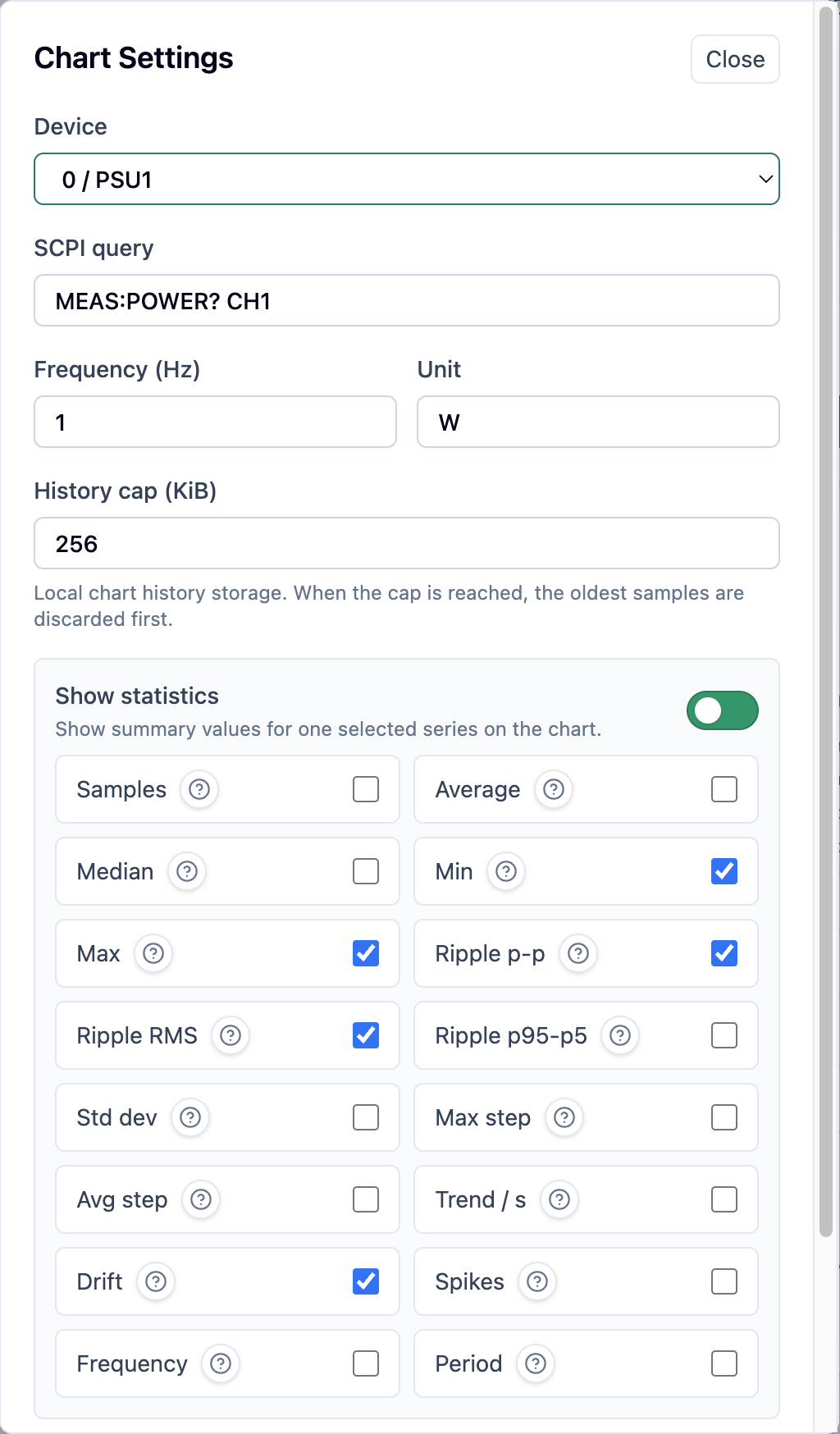
History is capped to a local byte budget, and the widget shows how much of that budget is currently used right in the header — "43.7/ 256 KiB" in one of our captures, for example. An eraser-icon action clears that history. There's also an optional statistics panel on this widget.
![]()
Chart Widget

Chart Widget Settings
Follow Along on Crowd Supply
If you're interested in PSU-EXT, subscribe to our pre-launch page on Crowd Supply: crowdsupply.com/maxeelabs/psu-ext
-
How We Got Here
08/25/2026 at 19:58 • 0 comments
Pro"log"ue
We keep coming back to the same starting point: a bench PSU that already does its one job well. It supplies voltage, it supplies current, and it's been sitting on the bench doing exactly that for years. The problem was never the PSU — it's everything around it. Watching it means standing there. Logging it means writing numbers down by hand, or propping a phone up to film the display. Automating it usually means buying a whole new instrument and retiring the one that already works.
We didn't want to go that route, so this project started small and has been growing outward from that one decision since.
Extend, don't replace.
A programmable PSU solves remote control by replacing the instrument you already own — that's the default answer, and it means the supply you already know, already trust, already paid for, goes in a drawer. We want the opposite: keep the PSU right where it is, and extend it in place instead of swapping it out. That's the constraint everything else here has to work around.
And it shouldn't be locked down.
Fine — but if we're keeping the PSU, we're not going to hand anyone a closed box either. A lot of "programmable" gear ships with closed firmware and a fixed feature set: whatever the vendor decided you get is what you get. That's not extension, that's a different flavor of lock-in. So the hardware, the firmware, and the software all stay open.
So it should speak SCPI.
Open is good, but open and mute doesn't help anyone driving a test bench. It needs to speak SCPI — the command language real instruments use for remote control. Give it SCPI over USB, then. Done?
Not quite. We add TCP too!
Most SCPI-capable gear is USB-only, or LAN-only — pick a lane and stay in it. We didn't see a reason to pick one. The same commands work whether you're plugged into a laptop on the bench or reaching the module over Wi-Fi from across the room.
Control isn't enough — make it automatable.
SCPI commands get you remote control, but remote control by hand is still someone standing at a keyboard instead of standing at a bench — that's relocation, not automation. On top of the commands, there's a scripting IDE and reusable dashboard widgets: something that runs a sequence and shows you the result, instead of waiting for you to type the next line.
And don't stop at this one PSU.
Once those widgets exist, why should they only know about this one instrument? They don't — they adapt to other SCPI-capable gear too.
Somewhere along the way, the project stopped being about one bench PSU at all, and that's still where the scope keeps expanding.
What PSU-EXT Is: One Module, Firmware, and a Dashboard
Concretely, here's where that thinking has landed so far. PSU-EXT sits inline between a bench power supply and a load, measures voltage, current, and power, and controls the output path with a relay. That's the current physical shape the five points above have taken.
"PSU-EXT" isn't just that board, though — it's three pieces that work together, each its own repo:
- Hardware — the module itself
- Firmware — runs on the module
- Software — the companion stack that talks to the firmware over USB or the networkSeparate repos, one product, moving in parallel.
Here's what it's built on right now:
Operating range 0–25 V, 0–2.5 A Board size 100 × 50 mm (3.94 × 1.97 in) Control connection USB-C (power and data) Controller Espressif ESP32-S3 Measurement front end ADS1115 ADC + INA240 current-sense amplifier Isolation Isolated I²C bus + isolated DC-DC (measurement domain) 
PSU-EXT Board
And here's what runs it today:
Capability
What it provides
Firmware & software Open hardware, firmware, and software — not closed or vendor-locked Control transports SCPI over both USB CDC and Wi-Fi/TCP Automation Built-in scripting IDE and reusable dashboard widgets Instrument scope Widgets adapt to other SCPI-capable gear too, not locked to this one instrument 
PSU-EXT Dashboard
What "Extension" Means, Depending on Who You Are
Every beat above leans on one word: extend. What that actually means in practice depends on who's using the extended PSU.
For makers and hobbyists, it's shaping up mostly as a second life for a PSU that's been sitting unused since something nicer came along. Extended in place, it comes back into rotation with capabilities it never shipped with — voltage, current, and power visible in a browser dashboard for a demo, livestream, or project video, or sitting between a battery and a load to watch voltage, current, and power fall through a discharge cycle.
For repair engineers, that same extension shows up as a controlled inline gate between the PSU and the device under test: set over-voltage and over-current behavior first, then switch the output on from the browser instead of reaching for the supply's front panel.
For more advanced engineers, extension is pointing toward an ecosystem rather than one instrument. The dashboard widgets aren't hard-wired to this one PSU — they adapt to other SCPI-capable gear too. Where that goes next is still open: the same scripting IDE and dashboard could in principle pick up a second instrument alongside it — a SCPI-capable electronic load, a signal generator, or a second PSU-EXT module on another rail — though the widgets don't ship pre-wired to any of those specifically today.
What's Next
We're going to keep logging this project as it moves forward, not just posting once and going quiet. Future entries will share the insights and progress updates as we get them, the problems and setbacks we run into along the way (not just the parts that went smoothly), real use cases as people put PSU-EXT to work, and the engineering and science behind specific decisions we've made — plus general behind-the-scenes updates on where things stand. We don't have a fixed list of what's coming next or when — this is a running log, and we'll fill it in as we go, including more on the open-source side of things (the three repos, the contribution process) as that keeps developing.
Follow Along on Crowd Supply
If you're interested in PSU-EXT, subscribe to our pre-launch page on Crowd Supply: crowdsupply.com/maxeelabs/psu-ext
PSU-EXT
Open hardware and firmware that sit inline with a bench power supply, adding live measurement, protection, and SCPI control.