stemforge.phil
-
Hyper S3 Rocket - V3 Prototype conclusions
2 days ago • 0 commentsThe V3 Prototype is mostly successful with a few small changes taking place.
![]()
- The current sensing was not adequate. A redesign of the dual mosfet was needed, though this was a quick process.
- Power Diodes were misaligned during manufacture. Consultation shows that I had created larger pads than required according to the datasheet, and this enabled the diodes to move and short. Simple change to diode footprint was needed.
- Reverse polarity circuit was successful for the external Battery pin of the MODULE board, and I decided to incorporate this for the JST connector also to save the board (and battery) from wrong polarity. Even though the JST PH 2.0 connector is polarized, there is no standard. I have gone with the (Red on the Right) option, as looking at the connector. I'll put a small video on YouTube for those that need to adjust their LIPO battery pins.
- With these few changes, the project is moving into pre-production status. The next board on order will have high quality ink, thicker internal copper and the changes mentioned. Also being tested is manufacturer's final board electrical testing, firmware flashing along with individual ESD packaging and package labelling. The next prototype is also going back to red and will have castellated pins for the four versions (LOGGER, DATA, CHARGE, MODULE).
- Note, MODULE is the only version with the copper for batteries connected at the B+ pin. All other versions use the JST connector.
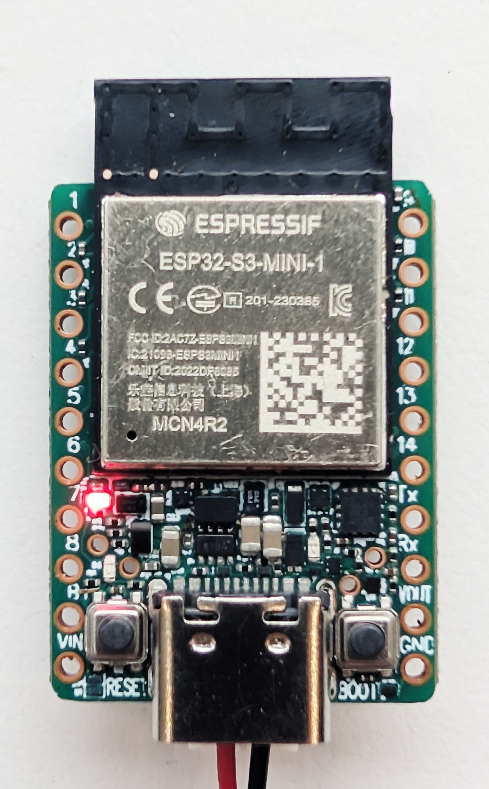
- Did some flight testing yesterday (02-11-26) with the five boards made by JLCPCB. Fortunately I noticed three of the boards had misaligned sensors on the LOGGER. Sensors affected were the Magnetometer and the Barometric Pressure sensor. To move forward, I'm incorporating testing within the firmware for the LOGGER with the Flight Code so all sensors will be tested by the manufacturer before shipping to enhance the reliability. It's understandable with these tiny sensors, but not acceptable going ahead.
-
PRECISE - Integrating the Truth - 10-DoF Sensor Fusion, No GPS Required
10/17/2026 at 03:45 • 0 commentsFive Sensors, One Flight: Recreating a Water Rocket’s Path Without GPS (even when Hitting the 16 g Wall)
Pump a soda bottle to 65 PSI, pull the pin, and the whole flight is over in seconds. No single sensor can tell you what happened in those seconds. The gyroscope drifts, the magnetometer is noisy, the accelerometer only knows “push,” and the barometer gets fooled by rushing air. But get them all talking to each other, and the HYPER S3 ROCKET can rebuild the entire flight in 3D, from pad to touchdown, without a single GPS fix.
Five sensors, one truth: rebuilding the flight from the inside
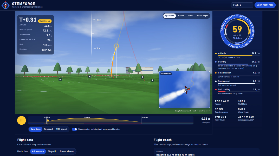
Here’s the part we’re most proud of. Every position in the 3D recreation (4:20) comes from the rocket’s own sensors working together. No GPS, no ground tracking, just correlated data and physics (5:16).
![]()
Step 1: Find the horizon. Before you can say where a rocket went, you have to know which way is level. On its own, each sensor gets this wrong in its own way. The gyroscope reacts instantly to every twist and roll, but its small errors build up over time and the horizon slowly tilts away. The magnetometer gives an absolute reference to magnetic north that never drifts, but it’s too noisy to trust moment to moment. Fused together (5:33), each corrects the other. The gyro supplies the fast, smooth motion, and the magnetometer keeps pulling it back to a fixed heading. The result is a stable, level horizon reference that holds through stages of boost, coast and tumble.
Step 2: Point the acceleration in the right direction. The accelerometer measures thrust along the rocket’s own body, and the rocket is pitching, rolling and weathercocking into the wind the whole time. Using the fused attitude from Step 1, every acceleration sample is rotated out of the rocket’s frame and into the oval’s frame: up, downrange and crosswind. Gravity is removed, and what’s left is the rocket’s true motion over the ground.
Step 3: Integrate to velocity, then to displacement. Integrate that world-frame acceleration once and you get velocity. Integrate again and you get displacement, mapped onto real XY coordinates across the oval (5:24). This is dead reckoning, the same principle that guided aircraft and submarines long before satellites.
Step 4: Cross-check against the barometer. Double integration is unforgiving, since any small error grows fast. So the vertical axis is checked against the barometric altimeter. Each sensor keeps the others honest: the barometer anchors height, and the inertial data exposes the altimeter’s pressure spikes at high speed (8:44).
Gyro (fast) + Magnetometer (stable) ➔ Level horizon & attitude            ↓
Accelerometer (body frame) ➔ rotated to oval frame ➔ minus gravity            ↓
∫ ➔ Velocity   ∫∫ ➔ Displacement (X, Y, Z)            ↓
Barometer cross-check ➔ 3D flight path
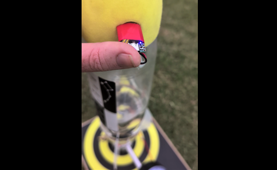
The payoff: a 3D flight recreation that follows the crosswind drift across the oval, with apogee within ±0.9 m and the landing point within ±4 m (9:49). That’s from a 4 gram board riding a fast soda bottle.
![]()
For students, this is the magic moment. Calculus stops being abstract when the integral of your rocket’s acceleration draws your rocket’s path across the screen, then shows the stages one by one and even recreates the tumble to the ground. Want a softer landing? - sounds like a plan.
-
PROTECT - The Battery in the Drawer is Everyone's Problem
10/10/2026 at 00:02 • 0 commentsThe Battery in the Drawer
Battery safety is a habit, but some habits could be better
Nothing dramatic happens to your pouch or 18650 lithium cell on the day it's ruined. There's no bang and no warning light. You put a gadget on a shelf or in a drawer with a little charge left, forget it for a few months, and when you come back the battery either won't charge, or charges and swells. That second outcome is the one worth worrying about. The damage was done weeks earlier, quietly, while everyone assumed the product was looking after itself.
If you've built a battery-powered project, there's a good chance it's protected the way almost every tutorial and dev board shows: one device doing one job. That's a reasonable thing to do, but is it safe? This log is about why one device isn't enough, why that isn't anyone's fault, and what it takes to do better.
Start with the safeguard most of us reach for first.
Why deep sleep isn't off
When the firmware sees a low voltage, say 3 V, it puts the microcontroller into its deepest sleep. It feels like switching the project off.
But the power rail is still live, and a hidden quiescent floor keeps drawing life from the cell:- Linear regulators with permanently enabled paths. A common AMS1117 draws up to about 5 mA typical (check your part's datasheet).
- A real-time clock, still ticking.
- Fixed voltage dividers that act as a permanent leak to ground.
Sleeping reduces the load. It doesn't disconnect it.
The numbers are worth working out once. At 5 mA, a full 1000 mAh cell lasts about eight days. A nearly flat cell is a very different story: the stretch between "almost empty" and "damaged" holds only a small fraction of its capacity, and 5 mA can cover that quickly. And if the firmware hangs, nothing is watching at all.
So software can't be the answer. Surely the hardware around it is.
Why the charger doesn't help
This is an easy mistake, and a very understandable one. A charging IC like the ubiquitous TP4054 sounds like battery protection for an 18650 or pouch, as it looks after the cell while charging. But it only manages charging. It isn't in the discharge path, so it never sees what the load does to the cell afterwards.
Then there's the protection under the tape.
Why the strip under the tape isn't the answer either
Many pouch cells come wrapped in yellow Kapton tape, and under it there's often a small protection board (PCM). That's a good thing to have, and it's better than nothing. But from the outside you can't tell whether the tape hides a real protection IC, a dummy board or bare solder joints. And even a working one, like a standard DW01A setup, is a last-resort breaker designed to act at the cell's absolute limit. It was never meant to be a product's shutdown strategy.
Each of these devices does its own job well. None of them was meant to be a lockout. Nobody has told us otherwise, because nearly every dev board and tutorial stops at one.
And that leaves a flat battery. If only a flat battery were the worst of it.
A dead cell isn't the worst outcome
Cell datasheets set the discharge floor at about 2.5 V. Push a lithium cell well below that, toward 0 V, and leave it there for days, and its chemistry starts to change. Copper from inside the cell can dissolve into the electrolyte. Then someone does the natural thing and plugs it into a charger. During that recharge, the dissolved copper can plate back out as tiny metallic spikes that may grow through the separator and short the cell internally. In the worst case that means heat, gas and swelling, and sometimes fire.
Most damaged cells never get that far. They just lose capacity and quietly become less trustworthy, which is the point: you can't see which cell is which. And many simple chargers don't check whether a cell has been pushed past the point of damage, since they were designed to charge cells, not to judge them.
If you ever find a cell that's been left flat for a long time, or one that's started to swell, the safest advice is to retire it and not recharge it.
For one person at one workbench, that's manageable. Now change the numbers.
What changes at 10,000 units
If a cell goes flat at home, you notice, you swap it and you move on. You're standing next to the thing, so you'd see it swell.
Now ship 10,000 of them, to homes, schools and workshops across the country or around the world. Nothing about any single board has changed. What changed is that you no longer know where they are or how they're kept.
Take an illustration, not a measurement. Suppose 1% of those units gets forgotten in a drawer long enough to reach the danger zone. That's 100 cells. Suppose 1% of those, once someone recharges them, fail badly. That's one incident. It takes only two small percentages to turn "unlikely" into "it will happen to someone".
The consequences scale with what one failure costs:- A fire in someone's home, or a hurt person. One incident is enough, and it won't feel like a statistic to the person it happens to.
- A recall. Pulling every unit back means tracing owners, replacing boards and paying for shipping in both directions.
- Liability and insurance. One incident can bring questions about what you did to prevent it, and "I relied on the cell's own protection" is a hard answer to give.
- Shipping and certification. Lithium batteries are regulated dangerous goods, and larger volumes mean closer attention from carriers, retailers and regulators.
- Trust. For a small maker, one story of a battery fire can end a product.
Scale makes the stakes real. A 2016 phone-battery recall, from a different cause, reached millions of units and cost billions.
At one unit, protection is cheap insurance. At 10,000 units, it's the difference between a product and a liability. So why doesn't everyone do it?
The honest objection: "Doing it properly is a project in itself"
It is, and that's the real reason most designs stop at one device.
A layered discharge lockout isn't one chip. It's a charger with a power path, a voltage supervisor, a comparator, an eFuse, MOSFETs, thermistors for temperature limits, reverse-polarity protection, and a layout that keeps switching noise away from all of it. Each part has thresholds that have to agree with the others, and each has to be tested. Get one value wrong and the "protection" quietly becomes a fault of its own.
And when you're building a wearable, a sensor node or a robot, none of this is your project. It's the diversion you take before your project can start. So most of us do the sensible thing under time pressure: pick one device, tick the box and move on.
That's the problem I set out to solve once, so you don't have to.
The fix lives in the power path
A lockout that works has to do one thing: put a real switch between the battery and everything else, and open it before the cell reaches its danger zone. The safety lives in the power path, the route current takes from the cell to your system. It doesn't live in application code and it doesn't live in the cell.
I built the HYPER S3 ROCKET around that rule, an ESP32-S3 board with the power path done properly, and then did it twice.
[ Li-ion/LiPo cell ] -> [ BQ25188 charger / power path ] -> [ eFuse + supervisor + comparator ] -> [ TPS631000 buck-boost ] -> [ 3.3 V rail, up to 2 A ]
Lockout one: the BQ25188 power path. The charger manages every charge and discharge cycle, prioritises the system load and isolates the battery from the rest of the board. Its battery undervoltage lockout (BUVLO) disconnects the cell below a threshold that firmware programs. I set it to [ ] V (default: [ ] V).
Lockout two: an independent eFuse, supervisor and comparator. A separate TPS259461 eFuse sits in the same path, with a voltage supervisor and a comparator watching it. It enforces under-voltage, over-voltage and over-current limits on its own, with the current limit set to 3.0 A and the under-voltage cutoff at 2.6 V. If the charger lockout fails, the eFuse steps in.
Once configured, neither lockout needs firmware to keep working. If the ESP32 crashes or hangs, both keep protecting the cell.Your project stays your project
All of this sits on a 20 × 33 mm board weighing about 4 g. The castellated MODULE variant solders flat onto your own baseboard like any other SoC module, so under a sensor node, a wearable or a robot, the battery safety is already done.
Because you don't have to spend your engineering budget rebuilding the power path from scratch, you can actually focus on your application. We designed this to be a powerful and flexible microcontroller platform. It features full battery fuel cell diagnostics—giving your code native visibility into real-time voltage and current metrics—alongside ultra-low-power management states and a hardware watchdog timer. With 16 external GPIOs broken out and completely unconstrained by safety overhead, what you build on top of it stays your project.
That's the shape I wanted the HYPER S3 ROCKET to have: small enough to disappear into your design, and careful enough that you never have to think about 'The Battery in the Drawer'.I'd like to hear from you: what's the worst battery failure you've seen in a product that should have known better? And what would you want measured first?
Temperature gets its own lockout
A cell can sit at a perfectly healthy voltage and still be in trouble, so the same power path watches heat. Two separate NTC thermistor inputs monitor the charging and the battery. The BQ charger monitors the cell temperature and adjusts charging accordingly, and the eFuse, supervisor and comparator add a discharge-side lockout at 58 °C. While one limits charging, the other provides the safety lockout. Together they keep the cell inside its safe temperature window, with the goal of keeping the cell alive.
This brings us to the number that matters most.
What the lockout buys you
When the cell reaches the cutoff, the hardware disconnects the load before the cell is over-discharged. In that locked-out state, the protection circuit typically draws 5.62 µA.
A 500 mAh cell would take roughly ten years to drain through 5.62 µA, so the cell's own self-discharge becomes the limit, not the board. A 5 mA regulator would flatten a 1000 mAh cell in about eight days. Leave the board in a drawer over the holidays, or for a year, and when you plug in USB or a solar panel it recovers by itself, with no reset and no re-flashing.
It also means a cheap charger is far less likely to meet a damaged cell. The cell is disconnected before it reaches the depths where damage starts, so whatever gets plugged in afterwards is much more likely to be charging a cell that's still in good shape.
Around the power path there's reverse-polarity protection on the USB and solar and B+ pin inputs, a keyed battery connector, and isolation so a solar panel can't back-feed a computer's USB port. Mistakes in a busy workshop are normal, so the hardware assumes them.
One board can only do so much, though. The bigger change is a habit.
This is a habit, and habits can change
I don't think any of this is down to carelessness. It's down to what we've learned to treat as normal.
Nobody ships a board without decoupling capacitors, and no one calls it fussy to add them. It became part of what "finished" means, so we stopped debating it. Battery safety hasn't reached that point yet. A dev board with one protection device can look complete and get praised in a review, and a project log can show a LiPo taped to a board with no one asking what happens when it runs flat. Nobody is being negligent in those cases. The question just isn't part of the conversation yet.
That's the part I'd like to change, and it doesn't need my board to do it. It needs a few questions to become ordinary:- What physically disconnects the battery? Not what tells the firmware to sleep. What opens a switch?
- What is the standby draw once the cell is low? Measured, not estimated, and ideally with the number in the documentation.
- What happens if the firmware hangs? If the answer is "the battery drains", that's worth knowing.
- What does the next charger meet? Would it be charging a healthy cell, or one that's been left too flat?
If those questions start appearing in forum threads, project logs and reviews, they stop being a special concern and become what "finished" means. At 10,000 units, that's the only version that scales: a norm everyone holds, not a heroic effort by a few.
I'd rather be held to it myself, so here is what I'm doing about it.
Prove it
The latest prototype, which adds the eFuse, supervisor, comparator and extra MOSFETs, with traces widened for currents up to 3 A, is in manufacture. In about two weeks I'll load-test and thermal-test it, and I'll post the discharge cutoff, the thermal trip points and the locked-out current here as scope and meter captures. If the numbers disappoint, you'll see that too.Your project stays in focus
With the form of a simple dev board and SoC, implementation to the next stage of your project with protection built in can be seamless. And with the time proven success of an Espressif S3 microcontroller, you possibly now have access to everything you might need on a single pcb. Of course, there are many features within the Hyper S3 Rocket that go beyond the realm of standard development boards and even beyond the theme of battery protection.Maybe the Hyper S3 Rocket is the boost your project it needs to send it to the next level, and this is how we at STEM FORGE would like to team up with you.
Protection is one Core Principle
Protection is one of four core underlying principles here at STEM FORGE. Now add in Power, Precision and Portability. The HYPER S3 ROCKET can disappear into your design or become a full-fledged platform and life-critical node. Don't let the flaws in life hold you back, there is so much more ready to take hold of.
Let's not worry about 'The Battery in the Drawer' anymore - grab a Hyper S3 Rocket and Send Your Projects Above Them All.
Our Crowd Supply fundraiser is on its way.
.
I'd like to hear from you: what's the worst battery failure you've seen in a product that should have known better? And what would you want me to measure first? -
Revisions for Latest Prototype and Rocket Launching tomorrow
10/09/2026 at 09:35 • 0 commentsPrototype in manufacture includes a number of quality and functional revisions, including upgraded trace width to handle up to 3A in places where it's needed. Will be load testing and thermal testing this prototype within the next 2 weeks.
The eFuse is a new addition as are a number of mosfets, the comparator and a supervisor chip.
Reverse polarity even on the MODULE external B+ pin
Got a new water rocket launcher yesterday and will get result up on youtube ASAP.
HYPER S3 ROCKET + Power Protect Precise Portable
Get ready for a fun event and challenge yourself to a whole new world of water rocket engineering & any other projects you can dream of