 Emanuele Carlino
-
1Step 1: Start Printin'
![]()
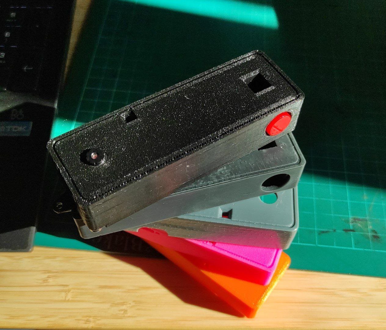
As usual, get the files and print them! Go to a friend and ask him to print them or do it yaself if you do have the printer.
I used PLA+ orange for my first verison and my last version, I like these bright colors. Go for 20% infill and use support material for the main body (the button hole is the main issue, I made it quite large but I can upload a model with a smaller hole. You might need to sand down the hole.
RESIN IS A BAD CHOICE! I tried using that, they came out so warped that it was funny, like some modern art sculture. -
2Step 2: Flash the Board
1. Set up the Arduino IDE
Install the ESP32 boards package (by Espressif Systems) in the Arduino IDE. You don't need any extra library, everything the firmware uses comes with it.
Then use these settings:
- Board: AI Thinker ESP32-CAM
- CPU Frequency: 240MHz (WiFi/BT)
- Flash Mode: QIO
- Flash Frequency: 80MHz
- Partition Scheme: Minimal SPIFFS (1.9MB APP with OTA/128KB SPIFFS)
- Upload Speed: 115200
The partition scheme is the important one, VERY IMPORTANT! With the default "Huge APP" there's no room for OTA updates.
2. Create your 'secrets.h' (optional)
Copy 'secrets.example.h' to 'secrets.h' (same folder as 'test_cam.ino') and fill in what you need. Everything is optional: without 'secrets.h' the camera works fine, it just won't have OTA, Telegram or Discord. An empty field means "feature off".
3. First upload (with a cable)
The very first time you need a cable, after that you can use OTA.
- Easiest: flash the ESP32-CAM before putting it on the PCB, using its dedicated programmer board (the ESP32-CAM-MB).
- On the PCB: use the programming header 'J1' with a USB-serial adapter (3.3V logic). Connect 'GND', 'TX' and 'RX' (TX to the adapter's RX and the other way around), put a jumper between 'IO0' and 'GND', and turn the camera on with the power button. Upload the sketch, then remove the jumper and power-cycle the camera. Don't connect the adapter's 5V pin, the camera is powered by the battery. You can use the programmer that usually comes with the camera board.
4. Updating over WiFi (OTA)
Set an 'OTA_PASSWORD' in 'secrets.h'. Without a password OTA stays off on purpose: the default WiFi password is public, so otherwise anyone nearby could flash your camera! (could be a funny prank to do on your friends)
Then you have two ways:
- Arduino IDE: connect your computer to the 'ESP32-CAM' network, pick the network port 'esp32-cam' and upload as usual. It will ask for your OTA password.
- Web page (works from a phone too): export the binary ('Sketch > Export Compiled Binary'), open http://192.168.4.1/update, log in with the user 'admin' and your OTA password, pick the '.bin' and press the button.
Caution!!!
DO NOT update with a nearly empty battery, and don't flash a firmware that breaks the WiFi: you'd lose OTA and you'd need the cable again. That's why the 'J1' programming header exists! (I had to use it, I am not too bright and forgot to set up the OTA password........yes, I'm a silly goose)
-
3Step 3: Telegram and Discord
The camera has to join a WiFi network with internet (your home router or your phone's hotspot) to send the photos. Put its name and password in 'secrets.h' ('STA_SSID' and 'STA_PASSWORD'). The camera's own network stays on, so you can still browse your photos.
Telegram
- On Telegram, talk to @BotFather, send '/newbot' and follow the steps. It will give you a token.
- Open a chat with your new bot and send it any message (like '/start').
- Open 'https://api.telegram.org/bot<YOUR_TOKEN>/getUpdates' in a browser and look for '"chat":{"id":...}'. That number is your chat id.
- Put the token and the chat id in 'secrets.h' ('TELEGRAM_BOT_TOKEN' and 'TELEGRAM_CHAT_ID').
Telegram recompresses normal photos. If you want the original file, set 'TELEGRAM_AS_DOCUMENT' to 'true' in the firmware.
Discord
- In your Discord server go to the channel settings, then Integrations, then Webhooks and create a new one.
- Copy the webhook URL and put it in 'secrets.h' ('DISCORD_WEBHOOK_URL').
How it behaves
Every photo is uploaded in the background, so you can keep shooting while the previous one is being sent. You'll hear a high beep when it's done or a low one if it failed. If the camera can't find your WiFi (say you're out and about) it tries for about 15 seconds, then gives up. Your photo is always saved on the SD card first.
THESE FEATURES ARE STILL BEING TESTED, check out the Github repo to remain in the loop or you might miss a firmware update that fixes any broken feature.
-
4Step 4: Soldering and Building It
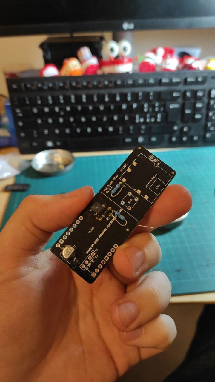
Before you solder the pins of the cam you need to do the SMD components (the capacitor and the buzzer), this will make it 100x times easier to assemble everything else. After doing the SMD part put the THT components in place, solder them and cut the excess wire of the components with flush cutters. When you are done with the two resistors and the diode you can do the 6x6mm button and the CKCS PB0A module, the ESP32 CAM and the last thing is gonna be the two wires that can connect the button to the PCB, that single piece had no easy way of being put on the board unfortunately. Also use a smudge of hot glue on the 12x12mm button.
![]()
Warning
The CKCS PB0A has no reverse polarity protection. If you connect the battery the wrong way, the module is dead, dead-dead-dead. The battery symbol on the module has a tiny "pin": that's the positive terminal (BAT+). Check your battery wires with a multimeter, cheap LiPos often come with the red and black wires the other way around from what you'd expect! I'm telling you this cuz I did, in fact, fry one and I have to buy another one.
For the buzzer, put a small diode (like a 1N4007 or a 1N4148) in parallel to it, with the stripe (cathode) on the side of the pin. It protects the pin from voltage spikes. Also put a bulk capacitor (you should use a 220uF) between 5V and GND, close to the ESP32-CAM. When you unplug the USB-C cable the charging module has a tiny power gap that can reboot the camera, the capacitor smooths it out.
-
5Step 5: Go out and Have Fun!
![]()
This is just the beginning of this project, the Github Repo for the FairCharm will always have the most up-to-date STL models and versions of the firmware, if you want to build it go there for the files, they will change and improve (trust me).
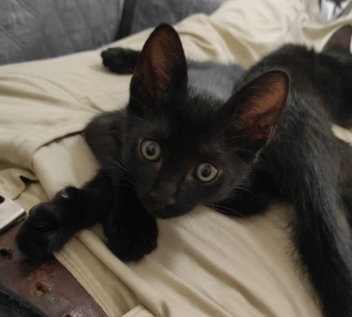
If you liked this project please consider donating a dollar to me and to my evil black cats that are now starting to understand how to climb smooth and frictionless surfaces with their secret powers. Here's the link for my Ko-Fi if you want to save me from them.
FairCharm
The Open Source Charm Camera, easy to repair and mod (+Telegram & Discord feature)
Discussions
Become a Hackaday.io Member
Create an account to leave a comment. Already have an account? Log In.