Emanuele Carlino
-
NEW PCB REVISION + ADDED EXTERNAL MODULES UPGRADE!!!
6 days ago • 0 commentsI know there are other projects like mine out there, I'm 100% aware of that, so I decided to say "fuck it, let's try to make it extra special". Here I am with Revision 3 of the PCB, I fixed the UART connector issue (I was mislead by the pin numbers and fuck'd up the traces, luckly I noticed that before doing anything extremely stupid) and decided to add out of the box the option of adding external modules to the camera!
PCBWay decided to sponsor this new board revision (thank you guys so so so much), in the near future I'll have ma hands on it and I'll test it out and iron out any weird problem that might show up.You can basically do any weird idea that comes up to you if you decide to use the external module feature, GPIO13 can be used ONLY on 1-bit mode for the microSD, GPIO03 is the RX bus for UART but it can be used as IO. The pins are meant to be used with ANY I2C sensor and all STEMMA QT (Adafruit) or Qwiic (SparkFun) sensors and modules. MAKE SURE THAT THOSE SENSORS HAVE A 4.7 or 10 kΩ resistor on SDA/SCL!!! Otherwise add an external one.
I'll post the new files soon.
"This is what you want, this is what you get!" -
Minor Setback and New Body that just Fits.
11/01/2026 at 23:04 • 0 comments![]() There are days where I wish I could chainsmoke 500 cigarettes and other days where I wish 1 gram of antimatter could touch me and instantly vaporize anything in a 10.000km radius including me, of course. The stupid knock-off module I bought from AliExpress to power up the board worked flawlessly untill I had to actually use it, now I can very easily cook an egg on the IC while I try to charge the battery.
AAANYWAY, some Good News!
- New fukin body, V1.7 and new backplate, V1.3.3.
- Testing will start soon, this module problem is a pain in my ass that needs to be fixed.
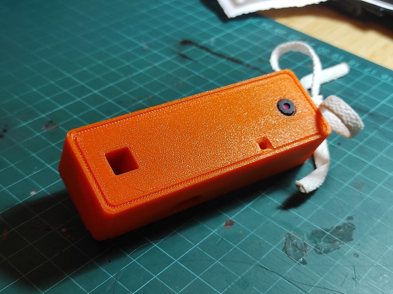
One thing I want to mention about the new body: in V1.6 the tolerances were too fkng tight and when I was trying to put the camera in the hole I pushed it back a little and RIPPED the lens clean off. I had to superglue it back together, hopefully this won't make my photos look like straight ass. To prevent this I made the interior walls 0.4mm thinner and added a sort of "ramp" for the cam to slide in.
-
Finally got the PCB + Real Field Testing soon!
10/27/2026 at 08:29 • 0 comments![]()
I gotta say something: this is my first time ever designing a PCB, all alone. It's not easy but it is fun. There were times where I wanted to punch the screen, scream and burn my PC down and other times when I was so happy looking at my stupid silly little board. I worked at this project at night so my R1.0 design was....holy shit it was, literally, shit. I had a row of pins in the reverse direction, the UART pins connected to the wrong esp pins, polarity in the CKCS module inverted (for the battery and the output!!!), vias connected to good ol' jack&shit...
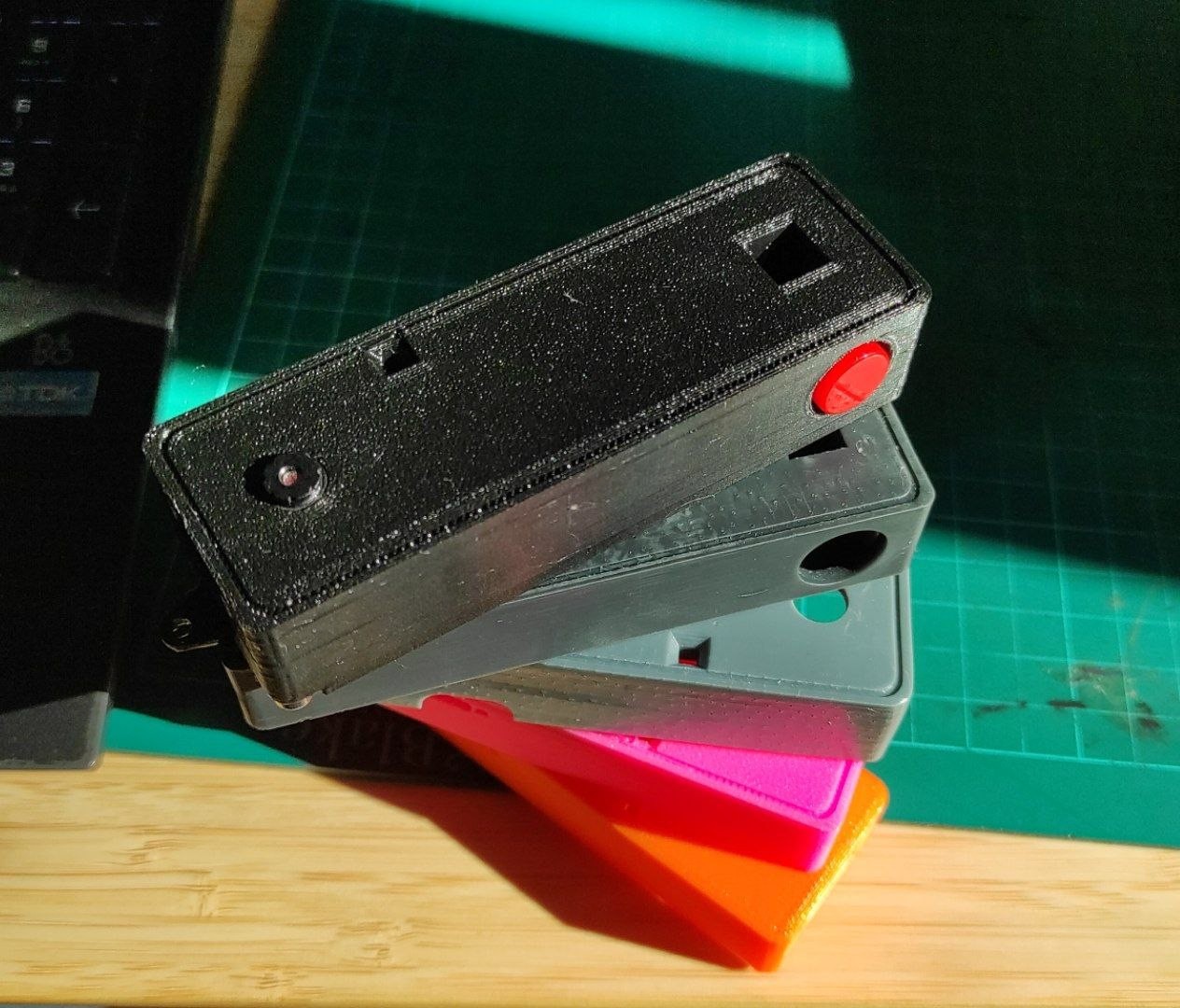
I am learning so much and it's actually incredible, I love it! Anyway, I got the parts I needed and I'll try to make a video about it in the near future. This is the tower of past-designs btw, the black one is not the definitive one but it's where I'm at now, it will change.
For now that's all Folks!
Funny little story: I asked my brother to print me some parts with his Bambu printer and let me tell you, either he does not know how to set it up properly or that printer got some serious issues, like, SERIOUS issues. The shit he gave me was all wobbly and crooked. I have a Ender 3 S1 Pro and that beat up machine beats that overpriced PoS. -
PCB and Firmware are live now!
10/13/2026 at 06:49 • 0 commentsI'm still testing everything and this is given as a prototype pre-Alpha. I'm waiting on the PCB and in the coming days I'll make some custom faceplate and backplate arts.
But yes, you can download everything right now and try to build it yourself! I highly suggest you to go to my github and check that out, it goes more in depth on how this all works. -
The PCB and the actual firmware are coming VERY soon
10/12/2026 at 16:08 • 0 commentsAs the title says, I'm almost done. Sorry everyone, I just can't bring myself to publish something if it's not up to my standards. The PCB is only revision 1 because, as you might imagine, I have never done a PCB before (I'm a CS person, not a EE) but STILL I've tried to do this a one shot typa thing, like good and done the first try typa thing. Anyway sorry but I still have to test out a few things before releasing the files so be patient, I'm almost done.
Please, if you think I'm making a huge mistake in the Gerber file feel free to destroy me in one bilion atoms, I am still learning, just don't be too mean.
Today I will probably publish the INO but that also needs more testing. I'm warning you: it might not work and it might suck but I will work on it.
FairCharm
The Open Source Charm Camera, easy to repair and mod (+Telegram & Discord feature)
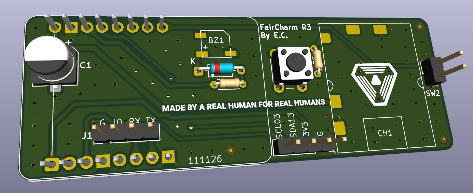 I know there are other projects like mine out there, I'm 100% aware of that, so I decided to say "fuck it, let's try to make it extra special". Here I am with Revision 3 of the PCB, I fixed the UART connector issue (I was mislead by the pin numbers and fuck'd up the traces, luckly I noticed that before doing anything extremely stupid) and decided to add out of the box the option of adding external modules to the camera!

 There are days where I wish I could chainsmoke 500 cigarettes and other days where I wish 1 gram of antimatter could touch me and instantly vaporize anything in a 10.000km radius including me, of course. The stupid knock-off module I bought from AliExpress to power up the board worked flawlessly untill I had to actually use it, now I can very easily cook an egg on the IC while I try to charge the battery.