Close
0%
0%

FairCharm

The Open Source Charm Camera, easy to repair and mod (+Telegram & Discord feature)

Similar projects worth following
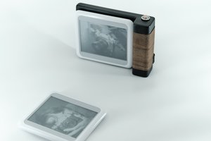
A pocket camera that fits in your hand and can hang from your bag like a charm! lt's fair
because it's open-source and free for everyone.

Just an ESP32-CAM project that came to my mind when I saw a certain company make
these poket cameras with a 1.6 megapixel camera that are kinda trash and way too stupidly
expensive/overpriced.

The people at PCBWay decided to help me out with the printed ciruitboard, shoutout to Aran and the fine people that work at PCBWay, they're providing me with a tight and clean PCB that will make this project free of any tangled and messed up wirenest.
Update: I recieved the PCBs and I have to admit, they are super nice, incredibly crispy silkscreen and the quality is just phenomenal. Perfect thickness, perfect aligment and everything is just...wow. Overall I gotta say their service was just perfect and they were extremely nice and polite with me.

I decided to give a shot to making a small camera after seeing a little tiny company, whose name starts with K and ends in odak, sell these sh*tty cameras for quite a lot of money and basically zero features, oh and if that isn't horrible enough already they sell them in this "WOOOOOOW YOU DON'T KNOW WHAT CAMERA YOU ARE GONNA GET!!! ALSO TRANSPARENT CASE SUPER DUPER RARE ONE!!!!!" way, peak consumerism...


So yeah, here I am, trying to make something that is actually cool. I want this camera to be able to send the pictures to Discord and Telegram, also I'll try to implement a static HTTP page when you connect to the ESP's WiFi with a carousel of the taken images. 

I'm gonna use a PCB but you can get away by using flying wires and whatnot. 

## What can it do?

- Takes photos with the OV2640 sensor of the ESP32-CAM (up to UXGA, 1600x1200, so roughly 2 megapixels) and saves them as JPG on a microSD card.
- Beeps to tell you what's going on (ready, photo taken, error, going to sleep...). No screen needed!
- Creates its own WiFi network. Connect your phone, open a web page and swipe through your photos in a little carousel. No app, no cloud, no account.
- Can optionally send every photo to a Telegram chat or a Discord channel as soon as you take it.
- Can be updated over WiFi (OTA), so you don't need to unscrew it and plug cables every time there's a new firmware.
- Goes to sleep by itself when you're not using it to save battery.

## Using it

1. Put the microSD card in the ESP32-CAM.
2. Press the power button (the one on the K pin of the charging module). The module has no on/off switch, that's the button that turns the 5V on.
3. Wait for 2 short beeps. That's the "I'm ready let's go" signal.
4. Press the big red button to take a photo. You'll hear 2 rising beeps when it's saved.
5. Done! The photos are on the SD card as 'photo_00001.jpg', 'photo_00002.jpg', and so on. The counter keeps going even after a reboot, so old photos never get overwritten.

The small flash LED on the ESP32-CAM stays dimly lit while the camera is on, it's on purpose: it's the "yes, I'm awake" light (it shares a pin with the shutter button).

### What do the beeps mean?

Sound Meaning 
2 short beeps Ready to shoot
1 short high beep (after a photo)Photo uploaded to Telegram / Discord
 2 rising beepsPhoto saved
1 long low beep (after a photo)Upload failed (the photo is still safe on the SD card)
2 low beepsError: the camera or the SD card didn't start, or the photo couldn't be saved
3 falling beepsGoing to sleep

### Sleeping and waking up

After 60 seconds without doing anything the camera goes into deep sleep. About 30 seconds later the charging module notices that almost no current is being used and cuts the 5V completely (that's its default behaviour, very nice for the battery life).

- Press the big red button to wake it up (works while it's still in deep sleep, so in the first ~30 seconds, or when it's plugged into USB-C).
- If the power was cut, press the power button on the charging module to turn it on again.

If your phone is connected to the camera's WiFi the sleep timer is 5 minutes instead of 1, so you have time to browse your photos or update the firmware.
(but you can totally change this and give yourself more time)

### Seeing your photos on your phone

1. Connect to the WiFi network called 'ESP32-CAM'. The default password is '12345678'. Please change it, it's in the firmware ('ap_ssid' and 'ap_password')!
2. Open http://192.168.4.1 in your browser.
3. You'll see the carousel: newest photo first, ◀ goes to the older one and ▶ to the newer one. You can also use the arrow keys on a computer or swipe on a phone. The Download button saves the current photo.

The ESP32 is a tiny chip, so photos take around 1 to 3 seconds to load. Be patient with it, it's doing its best!

## Telegram and Discord

The camera has to join a WiFi network with internet (your home...

Read more »
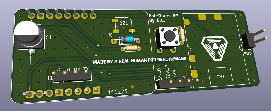
FairCharm_R3.kicad_sch

Revision 3 adds the possibility of adding external modules to your camera.

kicad_sch - 940.45 kB - 11/15/2026 at 11:41

Download

FairCharm_R3.kicad_pcb

Revision 3 adds the possibility of adding external modules to your camera. I also fixed AGAIN the UART trace and pinout, this time is right, sorry for the mistake.

kicad_pcb - 305.52 kB - 11/15/2026 at 11:41

Download

faircharm backplate v1.3.3.stl

Standard Tesselated Geometry - 235.73 kB - 11/01/2026 at 23:08

Download

faircharm body 1.7.stl

Standard Tesselated Geometry - 153.99 kB - 11/01/2026 at 23:08

Download

FairCharm_PCB_R2.3.kicad_pcb

Final revision, the dimension of the CKCS module was wrong, 3mm too short and the pads did not line up properly. Now it's fixed. This is the PCB schematics for the board.

kicad_pcb - 277.64 kB - 10/27/2026 at 07:52

Download

View all 10 files

  • 1 × ESP32-CAM Ai Thinker The main brain of this project.
  • 1 × CKCS PB0A To power on the board.
  • 1 × Lateral momentary push button This will be used with the CKCS module, on the K pin to power on /offf the circuit.
  • 1 × Li-Ion battery 500mAh 3.7V To connect to the CKCS module.
  • 1 × Momentary push button, the big 12x12 ones With a snap on red cap (or whatever color rocks your boat)

View all 10 components

  • NEW PCB REVISION + ADDED EXTERNAL MODULES UPGRADE!!!​

    Emanuele Carlino • 6 days ago • 0 comments

    I know there are other projects like mine out there, I'm 100% aware of that, so I decided to say "fuck it, let's try to make it extra special". Here I am with Revision 3 of the PCB, I fixed the UART connector issue (I was mislead by the pin numbers and fuck'd up the traces, luckly I noticed that before doing anything extremely stupid) and decided to add out of the box the option of adding external modules to the camera! 

    PCBWay decided to sponsor this new board revision (thank you guys so so so much), in the near future I'll have ma hands on it and I'll test it out and iron out any weird problem that might show up.


    You can basically do any weird idea that comes up to you if you decide to use the external module feature, GPIO13 can be used ONLY on 1-bit mode for the microSD, GPIO03 is the RX bus for UART but it can be used as IO. The pins are meant to be used with ANY I2C sensor and all STEMMA QT (Adafruit) or Qwiic (SparkFun) sensors and modules. MAKE SURE THAT THOSE SENSORS HAVE A 4.7 or 10 kΩ resistor on SDA/SCL!!! Otherwise add an external one. 

    I'll post the new files soon.

    "This is what you want, this is what you get!"

  • Minor Setback and New Body that just Fits.

    Emanuele Carlino • 11/01/2026 at 23:04 • 0 comments

    There are days where I wish I could chainsmoke 500 cigarettes and other days where I wish 1 gram of antimatter could touch me and instantly vaporize anything in a 10.000km radius including me, of course. The stupid knock-off module I bought from AliExpress to power up the board worked flawlessly untill I had to actually use it, now I can very easily cook an egg on the IC while I try to charge the battery. 
    AAANYWAY, some Good News!

    • New fukin body, V1.7 and new backplate, V1.3.3.
    • Testing will start soon, this module problem is a pain in my ass that needs to be fixed.

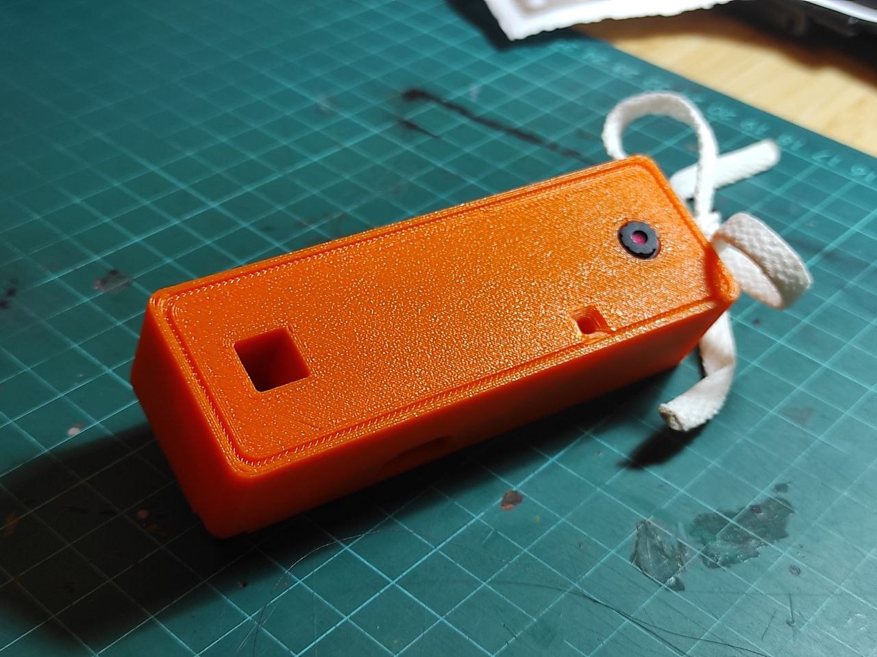
    One thing I want to mention about the new body: in V1.6 the tolerances were too fkng tight and when I was trying to put the camera in the hole I pushed it back a little and RIPPED the lens clean off. I had to superglue it back together, hopefully this won't make my photos look like straight ass. To prevent this I made the interior walls 0.4mm thinner and added a sort of "ramp" for the cam to slide in. 

  • Finally got the PCB + Real Field Testing soon!

    Emanuele Carlino • 10/27/2026 at 08:29 • 0 comments

    I gotta say something: this is my first time ever designing a PCB, all alone. It's not easy but it is fun. There were times where I wanted to punch the screen, scream and burn my PC down and other times when I was so happy looking at my stupid silly little board. I worked at this project at night so my R1.0 design was....holy shit it was, literally, shit. I had a row of pins in the reverse direction, the UART pins connected to the wrong esp pins, polarity in the CKCS module inverted (for the battery and the output!!!), vias connected to good ol' jack&shit...

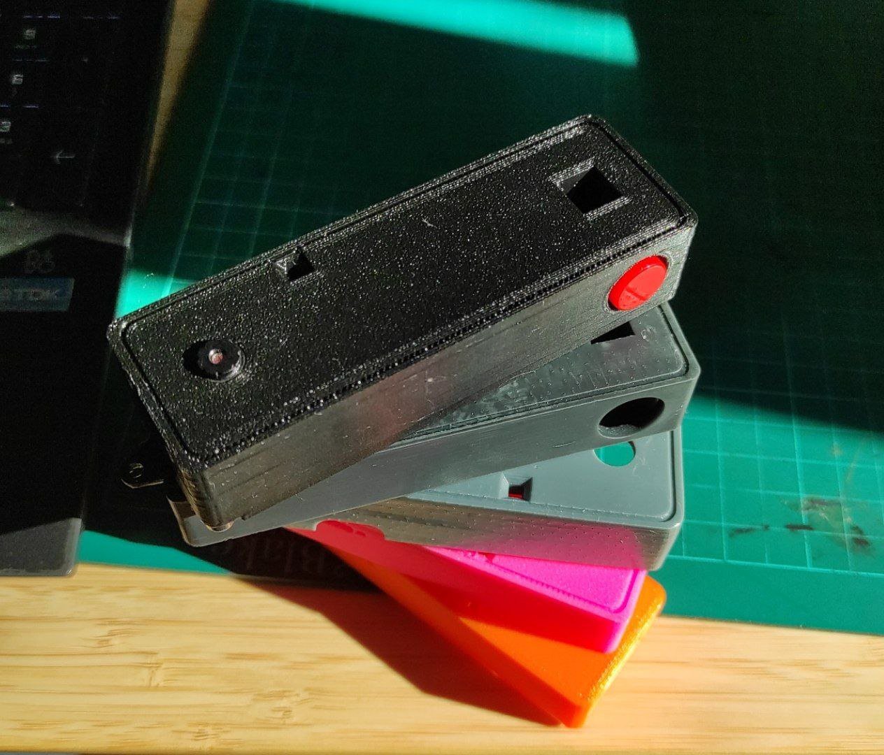
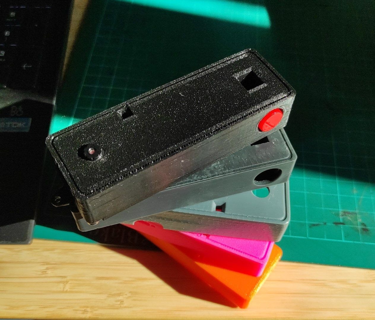
    I am learning so much and it's actually incredible, I love it! Anyway, I got the parts I needed and I'll try to make a video about it in the near future. This is the tower of past-designs btw, the black one is not the definitive one but it's where I'm at now, it will change.

    For now that's all Folks! 


    Funny little story: I asked my brother to print me some parts with his Bambu printer and let me tell you, either he does not know how to set it up properly or that printer got some serious issues, like, SERIOUS issues. The shit he gave me was all wobbly and crooked. I have a Ender 3 S1 Pro and that beat up machine beats that overpriced PoS.

  • PCB and Firmware are live now!

    Emanuele Carlino • 10/13/2026 at 06:49 • 0 comments

    I'm still testing everything and this is given as a prototype pre-Alpha. I'm waiting on the PCB and in the coming days I'll make some custom faceplate and backplate arts.
    But yes, you can download everything right now and try to build it yourself! I highly suggest you to go to my github and check that out, it goes more in depth on how this all works. 

  • The PCB and the actual firmware are coming VERY soon

    Emanuele Carlino • 10/12/2026 at 16:08 • 0 comments

    As the title says, I'm almost done. Sorry everyone, I just can't bring myself to publish something if it's not up to my standards. The PCB is only revision 1 because, as you might imagine, I have never done a PCB before (I'm a CS person, not a EE) but STILL I've tried to do this a one shot typa thing, like good and done the first try typa thing. Anyway sorry but I still have to test out a few things before releasing the files so be patient, I'm almost done. 

    Please, if you think I'm making a huge mistake in the Gerber file feel free to destroy me in one bilion atoms, I am still learning, just don't be too mean. 

    Today I will probably publish the INO but that also needs more testing. I'm warning you: it might not work and it might suck but I will work on it.

View all 5 project logs

  • 1
    Step 1: Start Printin'

    As usual, get the files and print them! Go to a friend and ask him to print them or do it yaself if you do have the printer.

    I used PLA+ orange for my first verison and my last version, I like these bright colors. Go for 20% infill and use support material for the main body (the button hole is the main issue, I made it quite large but I can upload a model with a smaller hole. You might need to sand down the hole.

    RESIN IS A BAD CHOICE! I tried using that, they came out so warped that it was funny, like some modern art sculture. 

  • 2
    Step 2: Flash the Board

    1. Set up the Arduino IDE

    Install the ESP32 boards package (by Espressif Systems) in the Arduino IDE. You don't need any extra library, everything the firmware uses comes with it.

    Then use these settings:

    1. Board: AI Thinker ESP32-CAM
    2. CPU Frequency: 240MHz (WiFi/BT)
    3. Flash Mode: QIO
    4. Flash Frequency: 80MHz
    5. Partition Scheme: Minimal SPIFFS (1.9MB APP with OTA/128KB SPIFFS)
    6. Upload Speed: 115200

    The partition scheme is the important one, VERY IMPORTANT! With the default "Huge APP" there's no room for OTA updates.

    2. Create your 'secrets.h' (optional)

    Copy 'secrets.example.h' to 'secrets.h' (same folder as 'test_cam.ino') and fill in what you need. Everything is optional: without 'secrets.h' the camera works fine, it just won't have OTA, Telegram or Discord. An empty field means "feature off".

    3. First upload (with a cable)

    The very first time you need a cable, after that you can use OTA.

    1. Easiest: flash the ESP32-CAM before putting it on the PCB, using its dedicated programmer board (the ESP32-CAM-MB).
    2. On the PCB: use the programming header 'J1' with a USB-serial adapter (3.3V logic). Connect 'GND', 'TX' and 'RX' (TX to the adapter's RX and the other way around), put a jumper between 'IO0' and 'GND', and turn the camera on with the power button. Upload the sketch, then remove the jumper and power-cycle the camera. Don't connect the adapter's 5V pin, the camera is powered by the battery. You can use the programmer that usually comes with the camera board.

    4. Updating over WiFi (OTA)

    Set an 'OTA_PASSWORD' in 'secrets.h'. Without a password OTA stays off on purpose: the default WiFi password is public, so otherwise anyone nearby could flash your camera! (could be a funny prank to do on your friends)

    Then you have two ways:

    1. Arduino IDE: connect your computer to the 'ESP32-CAM' network, pick the network port 'esp32-cam' and upload as usual. It will ask for your OTA password.
    2. Web page (works from a phone too): export the binary ('Sketch > Export Compiled Binary'), open http://192.168.4.1/update, log in with the user 'admin' and your OTA password, pick the '.bin' and press the button.

    Caution!!!

    DO NOT update with a nearly empty battery, and don't flash a firmware that breaks the WiFi: you'd lose OTA and you'd need the cable again. That's why the 'J1' programming header exists! (I had to use it, I am not too bright and forgot to set up the OTA password........yes, I'm a silly goose)

  • 3
    Step 3: Telegram and Discord

    The camera has to join a WiFi network with internet (your home router or your phone's hotspot) to send the photos. Put its name and password in 'secrets.h' ('STA_SSID' and 'STA_PASSWORD'). The camera's own network stays on, so you can still browse your photos.

    Telegram

    1. On Telegram, talk to @BotFather, send '/newbot' and follow the steps. It will give you a token.
    2. Open a chat with your new bot and send it any message (like '/start').
    3. Open 'https://api.telegram.org/bot<YOUR_TOKEN>/getUpdates' in a browser and look for '"chat":{"id":...}'. That number is your chat id.
    4. Put the token and the chat id in 'secrets.h' ('TELEGRAM_BOT_TOKEN' and 'TELEGRAM_CHAT_ID').

    Telegram recompresses normal photos. If you want the original file, set 'TELEGRAM_AS_DOCUMENT' to 'true' in the firmware.

    Discord

    1. In your Discord server go to the channel settings, then Integrations, then Webhooks and create a new one.
    2. Copy the webhook URL and put it in 'secrets.h' ('DISCORD_WEBHOOK_URL').

    How it behaves

    Every photo is uploaded in the background, so you can keep shooting while the previous one is being sent. You'll hear a high beep when it's done or a low one if it failed. If the camera can't find your WiFi (say you're out and about) it tries for about 15 seconds, then gives up. Your photo is always saved on the SD card first.

    THESE FEATURES ARE STILL BEING TESTED, check out the Github repo to remain in the loop or you might miss a firmware update that fixes any broken feature.

View all 5 instructions

Enjoy this project?

Share

Discussions

Similar Projects

Does this project spark your interest?

Become a member to follow this project and never miss any updates