Jeff Wisgo
-
Log 10: Hopping under a heavy beam (November 2, 2026)
4 hours ago • 0 commentsUntil now the leg had only moved its own weight, swinging in the air. A real leg has to hold up part of a robot, push it and catch it again. So this time I gave it something heavy to carry.
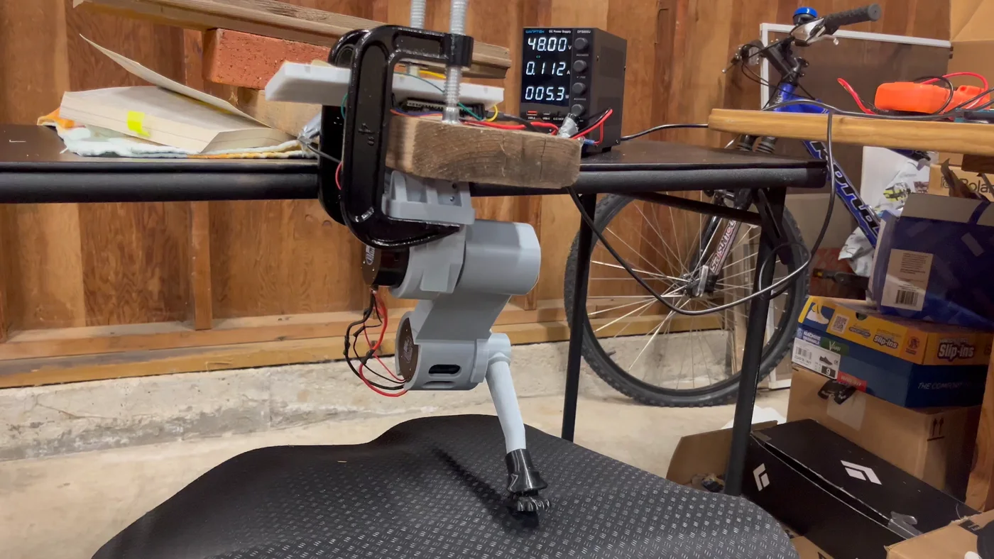
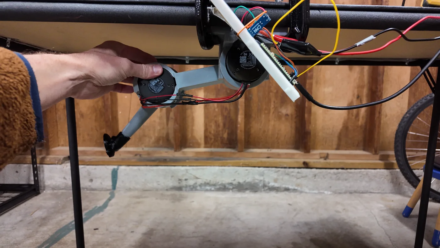
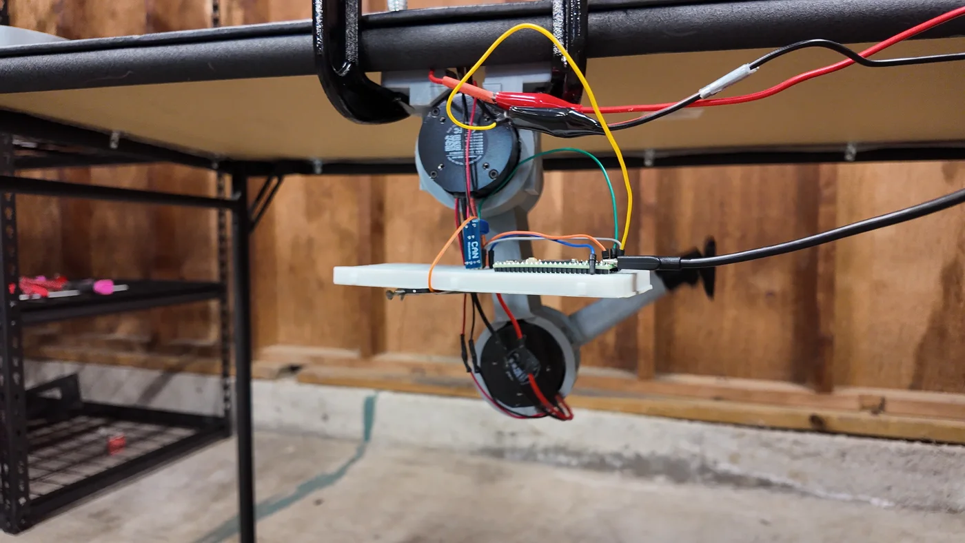
The setup is simple. A wooden beam lies flat on the table with one end sticking out over the edge. The hip mount is C-clamped under that end, and the foot stands on a rubber mat below. A brick sits on the far end of the beam. When the leg straightens, it lifts its end of the beam off the table. The leg measures the load itself from the knee torque, and it came to about 11 to 18 N, the weight of 1.1 to 1.8 kg on the foot. Later I took the brick off and held the far end by hand, which made it 21 to 25 N.
![The PLA leg C-clamped under the end of a wooden beam with a brick on it, its foot standing on a black mat]()
The beam rig: hip mount clamped under the beam, foot on a matHolding and bouncing
First, two 30-second holds: 11 N with the foot 224 mm below the hip, and 22 N at 245 mm, where the beam end rose 7.5 cm. Both were steady. Then four bounces, with the foot moving up and down in a smooth wave, from 10 mm once a second up to 20 mm twice a second. The knee never needed more than 2.3 N·m, and the motors stayed at 25 to 27 °C.
Single hops
A hop here means the leg pushes down fast enough that the foot leaves the mat, then catches the beam as it comes back down. I asked for faster and faster pushes, measured as the speed of the foot at the end of the push.
Push asked for What happened Peak knee torque 0.3 m/s The foot barely left the mat 2.1 N·m 0.5 m/s About 0.1 s in the air 3.0 N·m 0.7 m/s First try stopped itself (see below), then 0.65 m/s 4.5 N·m 1.0 m/s Launched at only 0.73 m/s 5.9 N·m The first 0.7 m/s try was stopped by a safety check, because the top of the push came too close to a fully straight knee. Lowering the top of the push fixed that. For these hops I also used the higher current-loop gain from Log 9, and it made a clear difference. With the factory value the knee trailed its command by 10 to 14 ms during a push. With the new value that dropped to 2 to 4 ms.
The 1.0 m/s hop fell short, but the motor wasn't the reason. The knee reached 5.9 N·m with 8 allowed. The push only lasts about 54 ms, and my controller doesn't yet ask for enough torque early enough. That's a software fix.
Successive hops
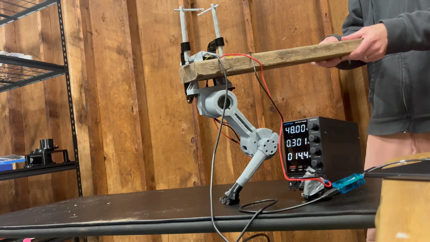
Chaining hops is harder. Each landing has to be detected, slowed down and turned straight into the next push. Catching the beam with plain soft control let the knee sag up to 0.3 rad. So instead the leg follows a planned slowdown path as it lands, and the motor stiffness ramps back up during it. That kept the knee within about 0.1 rad of its path. Ten hops in a row at 0.7 m/s ran cleanly.
![The leg pushing the beam up off the table while a hand steadies the far end of the beam]()
One of 20 hops in a row (watch the video)At 0.8 m/s two new problems showed up. First, the beam pumps up. Each push lands while the beam is still moving, so with the same push every time the hops got higher and higher, from about 0.1 s in the air to as much as 0.25 s. The fix was to adjust each push based on how long the last hop stayed in the air. Second, the foot kept pushing about 50 ms longer than planned, because of the remaining lag. So the leg now times each hop from the moment the knee actually unloads. With both changes, 20 hops in a row at 0.8 m/s worked, twice. The second run aimed for 0.163 s in the air and averaged almost exactly that.
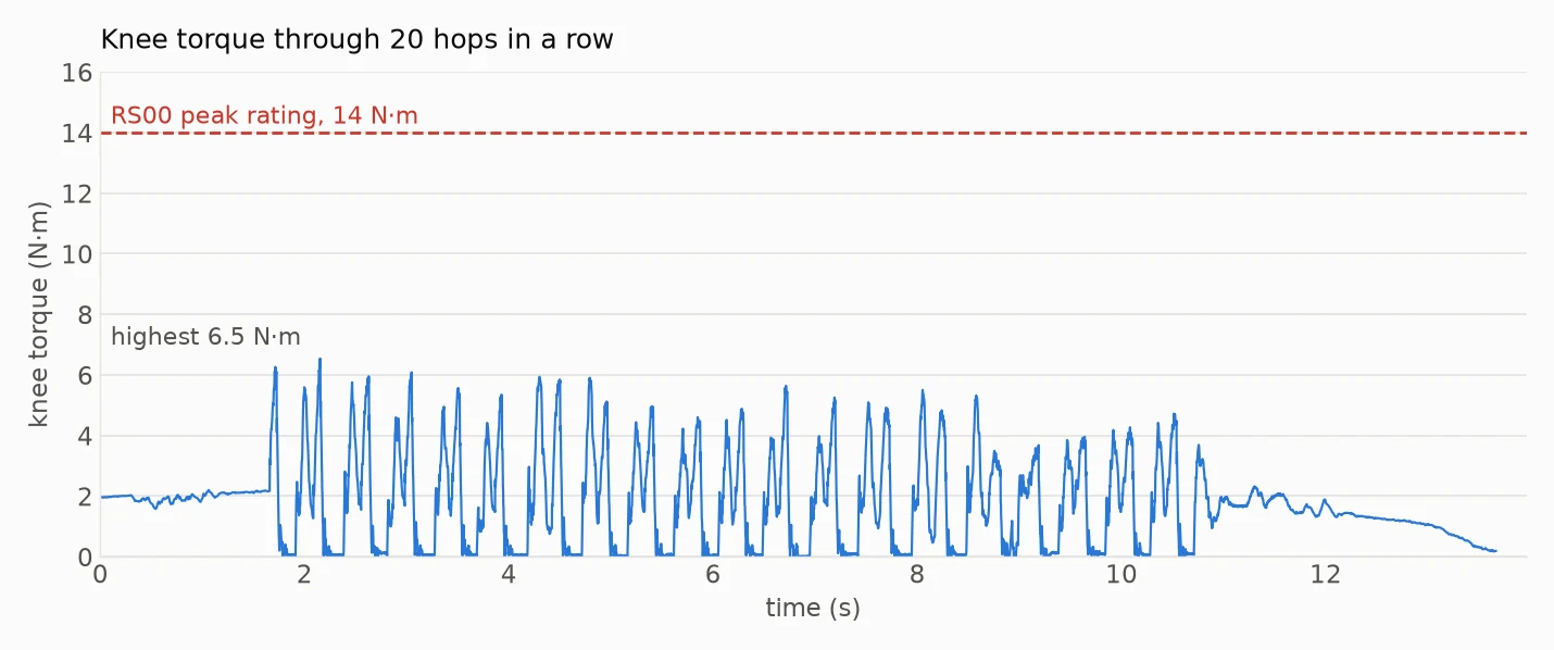
![Chart of knee torque against time: about 2 N·m while holding, then 20 spikes of 3.5 to 6.5 N·m during the hops, all far under a dashed line at the 14 N·m peak rating]()
Knee torque through the 20 hops, against the motor's peak ratingWhat the motors showed
- Torque was never the limit. The hardest knee push was 6.5 N·m, about 46% of the RS00's 14 N·m peak rating.
- Speed and power have room to spare. The knee peaked at about 10.7 rad/s, around 40% of its rated speed, and about 65 W of its rated 140 W.
- Heat didn't matter in these short tests. Every run stayed at or under 26 °C, and 20 hops warmed the knee by only 3 to 5 °C. The big heat question is still long walks, which this doesn't answer.
- The hip worked harder than I expected on landings, up to 5.7 N·m. The foot often landed a bit off-center, and the hip dragged it back. Next time the leg should plan from where the foot actually lands.
The weak link: a power wire
The knee motor's 48 V wire pulled out of its plug twice during chained hops. I soldered it back on. The lesson is that the leg cables need strain relief before this leg walks or hops on a robot.
A spark from the capacitors
Later, when I moved the power supply, the capacitors fell out. When I put them back in, with the supply off, there was a spark. When I checked them with a multimeter, they showed over 3 V, even though they were unplugged from the supply. I discharged them through a resistor for a few seconds until they read under 1 V, and the next try had no spark. Both motors were fine afterwards. The lesson here is to tape the capacitors tightly to the power supply, and to check their orientation when putting them back in.
Next steps
Strain relief for the knee cable. A better push that actually reaches 0.9 to 1.0 m/s. Planning each hop from where the foot lands. Then a slow squat under the beam, stepping in place under load, and finally a long run to test knee heat.
-
Log 9: Kicks, and a hidden torque limit (November 1, 2026)
4 hours ago • 0 commentsThe morning started with check 6, the foot press. The first run worked mechanically, but the bathroom scale read 1.5 to 2 times the force the motor torques predicted, so that check isn't passed yet.
Then something more fun: a kick test. A kick pushes the motors much harder than the slow walking gait, so it tests speed and torque. The first version was a small scoop under the hip, which looked nothing like a kick. The second swung the leg from far back to far forward. The version that stuck is a whip kick: the leg starts almost straight and far back, the hip swings forward, and the knee snaps the foot through at the end, the way a person kicks a ball.
I ran it as a ladder, speeding up one step at a time. Each speed is how fast the foot is moving at its fastest point.
Foot speed Whole kick Peak hip speed Peak knee speed 1 m/s 1.2 s 2.9 rad/s 3.0 rad/s 2 m/s 0.6 s 5.7 rad/s 6.1 rad/s 3 m/s 0.4 s 8.6 rad/s 9.5 rad/s 4 m/s 0.3 s 12.3 rad/s 13.3 rad/s Getting to 4 m/s took some work. The first try at that speed stopped itself halfway, because the knee fell too far behind its planned path and the safety check cut it off. Two changes fixed it: stiffer control during the swing only, and spreading the knee snap over a longer part of the kick so the knee needs less torque.
Kicking things
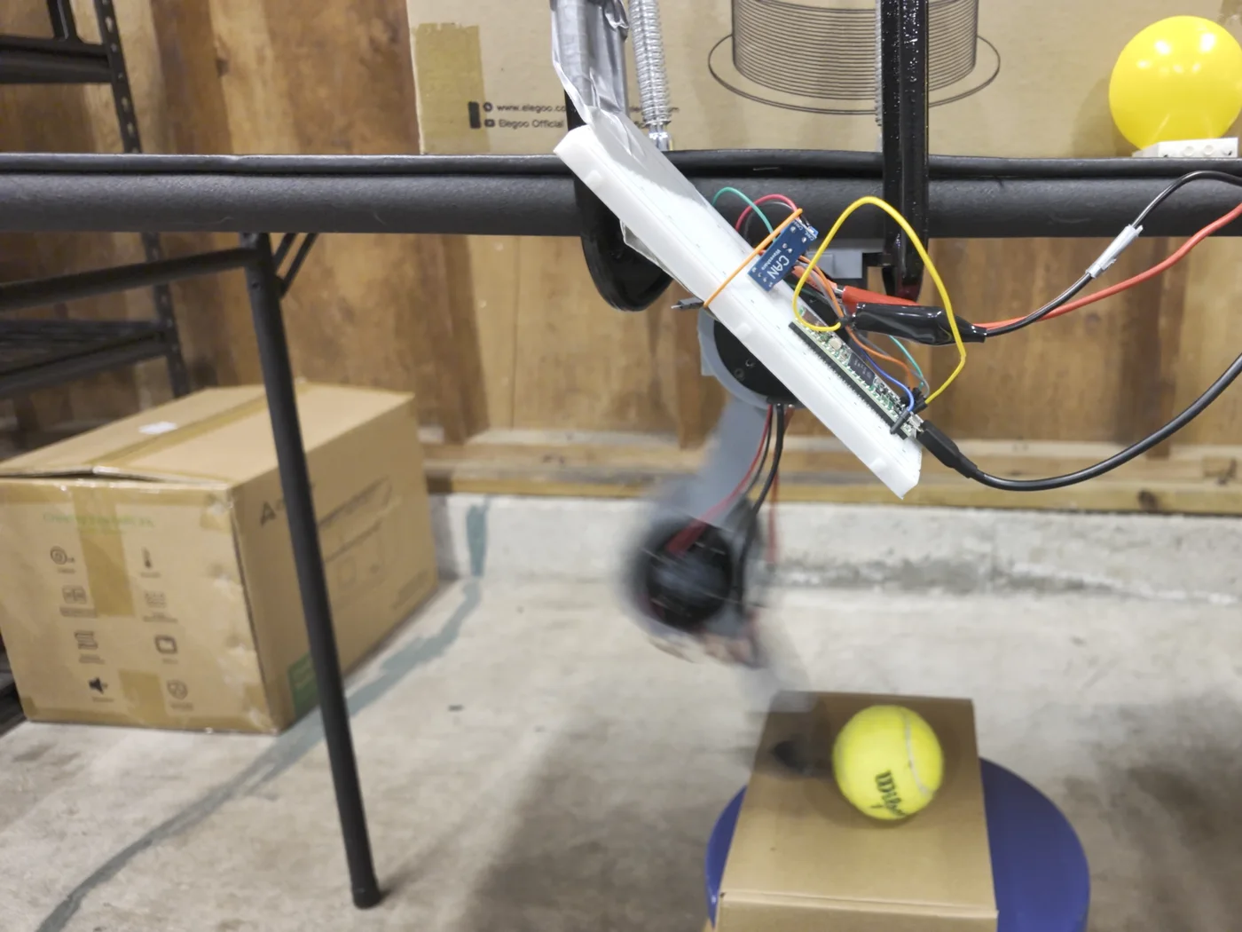
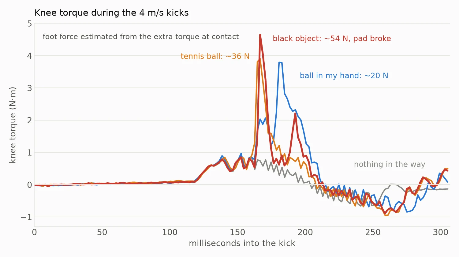
Next came five more 4 m/s kicks, five seconds apart, with something new on a box each time: a tennis ball, a ball held in my hand, a toy car, a black object, and finally nothing. The motors log their torque 500 times a second, so every hit shows up as a spike. From the extra torque at the moment of contact, and the leg's geometry, I can estimate how hard the foot hit.
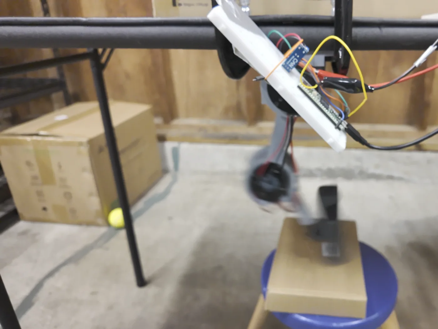
![The leg swinging down toward a tennis ball sitting on a box]()
A 4 m/s kick about to hit a tennis ball (video)Object Result Foot force (estimate) Tennis ball Knocked off the box about 36 N Ball in my hand Glancing hit about 20 N Toy car The foot swept just over it none Black object Knocked off, and the foot pad broke about 54 N ![Chart of knee torque against time during four 4 m/s kicks: a flat line with nothing in the way, and sharp spikes up to about 4.7 N·m for the three hits]()
Knee torque during the kicks: each hit is a spikeThe hardest hit broke off the PLA foot pad. Before the test I had guessed the printed foot would handle about 35 N from the side. The 36 N tennis ball was fine and the 54 N hit wasn't, so that guess was about right. The next foot needs to handle at least 60 N with some margin.
![The leg mid-kick, knocking a black object off the box]()
The 54 N hit that broke the foot padA hidden torque limit
Something had bothered me all day. In fast moves the knee never seemed to make much more than 1 N·m, even when the controller asked for much more. Yet during the hits it showed 4.7 N·m. So I gave each motor short torque pulses with the leg swinging freely, and worked out the torque it really delivered from how fast the leg sped up. Both motors fell far short: asked for 4 N·m, the knee delivered about 0.9 in a 10 ms pulse and the hip about 2 in 20 ms. Held still and given time, they always got there. The motors just couldn't build torque quickly.
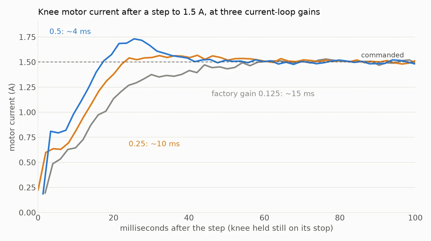
I ruled things out one at a time. The 48 V supply didn't sag at all during the pulses. A filter setting that looked suspicious in the manual made no difference. What did matter was the gain of the motor's current loop, the controller inside the motor that pushes current through the windings. The factory value is 0.125. Raising it to 0.5 made the current rise about four times faster.
![Chart of knee motor current after a step to 1.5 A: at the factory gain it takes about 60 ms to settle, at 0.25 about 25 ms, and at 0.5 it overshoots slightly and settles within about 40 ms]()
The same current step at three current-loop gainsMeasurement Factory gain (0.125) Gain 0.5 Current rise time (time constant) 11 to 15 ms 3 to 5 ms Knee torque from a 4 N·m, 10 ms pulse about 0.9 N·m about 2.1 N·m Hip torque from a 4 N·m, 20 ms pulse about 1.8 N·m about the full 4 N·m Knee off its path in the 4 m/s kick 3.6° 1.2° This is a big deal for the robot. Catching a stumble, landing a jump or swinging a leg fast all need torque within a few milliseconds, and the simulation assumes the motors can deliver it. With the factory setting they couldn't. For now the new gain isn't saved in the motors: the Teensy sets it before each fast test, and a power cycle restores the factory value. I've asked RobStride whether 0.5 is safe to keep.
One more lesson from the day: flashing the Teensy kept hanging for an hour. The cause turned out to be Google Chrome holding the board's USB connection open. Closing Chrome before flashing fixed it.
Next steps
A stronger foot, made to take at least 60 N. The sharper, later knee snap I wanted for the kick, which should work now that the knee can build torque quickly. A longer run of fast kicks to check heat with the new gain. And the foot press, to sort out why the scale and the motor torques disagree.
-
Log 8: Checks before printing more legs (October 31, 2026)
4 hours ago • 0 commentsWith one leg working, the next step is printing three more and switching from PLA to PAHT-CF, a stronger nylon filled with carbon fiber. Before spending that time and filament, I wanted to prove as much of the design as I can with this one leg. So I made a list of checks, ordered from safest to riskiest, and started working through it the same night.
Check What it shows Result 0. Walking gait The leg can follow a planned foot path Pass (Log 7) 1. Zero after power cycles The joint angles stay right after the power is cut, so no homing step is needed Pass 2. Full-range sweep The cables don't pull, pinch or rub anywhere in the range Pass 3. Gravity hold The leg's mass, its balance point and the motor's torque reading all match the model Pass 4. Free swing Inertia and friction at the hip match the simulation Pass 5. Endurance 30 to 40 minutes of walking, then a check for loose bolts, wear and heat Next 6. Foot press The foot pushing down on a bathroom scale matches the force the motor torques predict Next Zero after power cycles
The motors measure their output angle with a built-in sensor. If that reading drifted every time the power came back on, all the joint limits I measured by hand would be wrong after a restart, and the robot would need a homing routine. So I switched the supply off and on five times without touching the leg. The Mac read both angles three seconds after each restart and spoke a cue for the next one. The hip read 0.639 rad and the knee 2.700 rad every single time. The spread was zero, finer than the sensor's own steps of about 0.02°.
Full-range sweep
Each joint moved slowly to both ends of its range and held there, and then both joints went to all four corner combinations together. At every position I watched the cables at the thigh slot and around the hip. Nothing pulled, pinched or rubbed. This only covers the range I can reach on this rig, though. The simulation uses a wider hip range, so the cable routing needs another look before the robot uses all of it.
Gravity hold
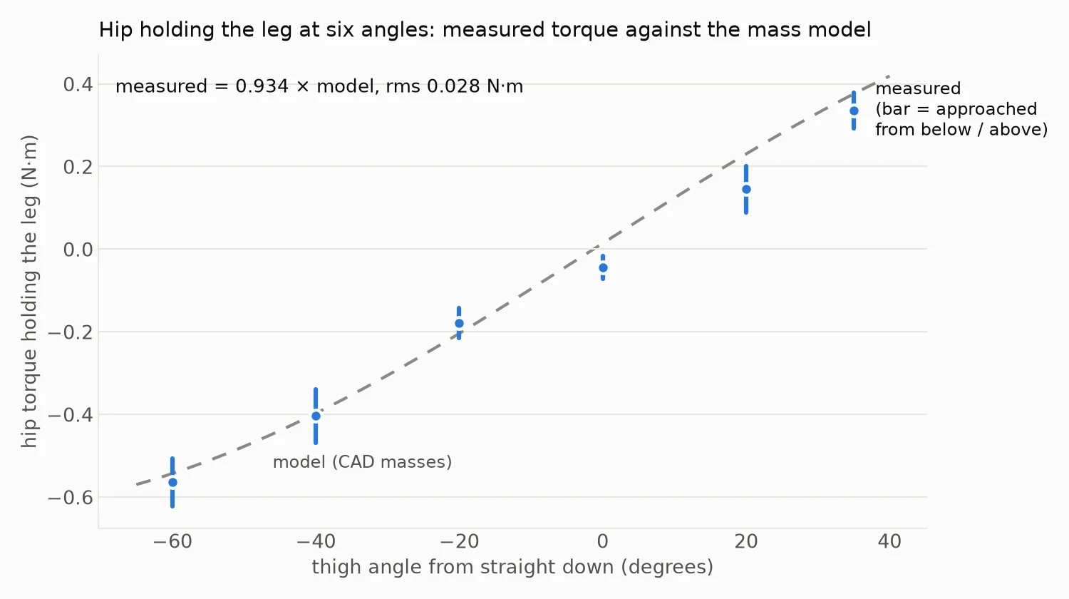
The hip motor held the leg at six angles from 60° back to 35° forward, approaching each angle once from below and once from above, while the Teensy averaged the motor's own torque reading. Holding still, all of that torque is just the weight of the leg pulling down. I compared it with what the CAD model says the printed parts weigh and where their balance point is. The measured torque came out at 0.934 times the model, within 7%. The gap between approaching from below and from above shows about 0.05 N·m of friction.
![Chart of hip torque against thigh angle: six measured points with small bars sit on the dashed model curve]()
Measured hip torque against the mass model at six anglesThat confirms two things at once. My method for working out each part's mass from the slicer settings works. And the motor's torque reading can be trusted even at these small loads, about 4% of its maximum.
Free swing
This one took a few tries. The idea was to lift the leg, let the hip go completely limp, and time the swings like a pendulum. The swing period depends on how much the leg resists being turned, its inertia. That includes the motor's spinning parts, which the simulation counts as extra inertia on each joint.
On the first try the leg sank slowly and stopped dead. The commands that switch the motor into its limp mode had gone out too close together, so the motor never switched and stayed in its "off" state, where it acts like a brake. With short gaps between the commands it worked, and the motor confirmed it was limp, but the leg still only sank to hanging without swinging. To rule out the motor's controller, I cut the power and dropped the leg by hand. It did exactly the same thing. So the drag is in the hardware itself, the gearbox and seals, and the light PLA leg barely outweighs it.
![A hand holding the leg up high, about to let it drop, with the motors unpowered]()
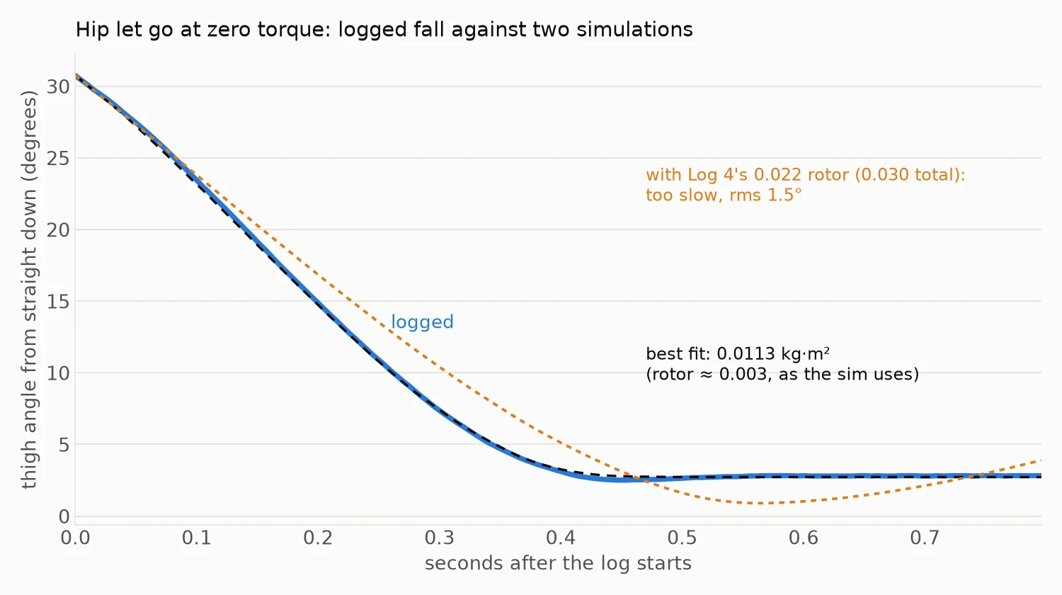
The unpowered drop test: lift the leg high and let goWatching that video closely, though, the leg did swing past hanging once when I let it go from high up, then settled. One swing isn't enough to time a period, but there's another way. I simulated the fall with different values for inertia and friction and kept the one that matched the logged angle best. The match was very good, within 0.04° on average. Other inertia values didn't fit nearly as well.
![Chart of thigh angle against time after release: the logged fall and the best-fit simulation overlap, while a simulation with a heavier rotor falls too slowly and overshoots]()
The logged fall against two simulationsThe best fit puts the inertia at 0.0113 kg·m² about the hip. The leg's own share, from the CAD model, is about 0.0086, which leaves about 0.003 for the motor's spinning parts. That's the value the simulation has used all along. Friction came out at about 0.15 N·m, also close to what the simulation assumes.
This changes one conclusion from Log 4. There I wrote that the inertia from an earlier bench test stood, at about 0.022 kg·m². This test rules that out for the hip motor. My best guess is that the earlier test also counted the lever bolted to the motor, but I haven't checked that yet. Either way, the simulation runs I redid with 0.022 should go back to 0.003.
Next steps
The firmware for the last two checks is written and on the Teensy. The endurance run will loop the walking gait for 30 to 40 minutes, then I'll check every bolt and the knee and hip bosses for loosening, cracks or wear. The foot press puts a bathroom scale under the foot at the standing pose and pushes down in steps up to about 2 kg. The scale reading should match the force the motor torques predict. After that, one thigh in PAHT-CF and a small test piece for the heat-set inserts, before printing the full set.
-
Log 7: The whole leg on the bench (October 31, 2026)
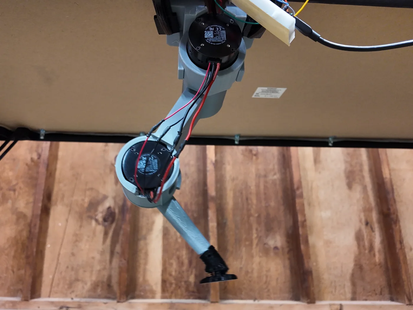
4 hours ago • 0 commentsUp to now each motor had been tested alone on a stand. This is the first time the full leg came together: the hip motor in its printed mount, the knee motor inside the printed thigh, and the shank and foot below it. Everything is still the gray PLA fit-check print of leg 1.0e.
The night before, I put the knee motor into the thigh on its own and found its range by hand. With the shank against its end stop the motor reads 2.721 rad, and the design allows 120° of bend from there. Then came the first powered knee moves: 30°, 73° and 113°, each slow, held for two seconds and brought back. After that, a smooth back-and-forth sweep up to 4 rad/s. No faults, and the motor stayed at 15 °C.
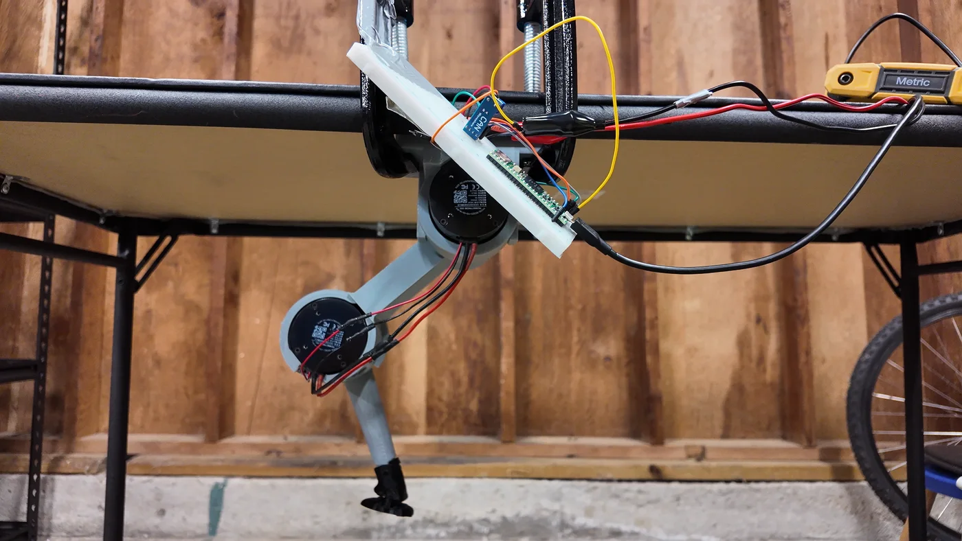
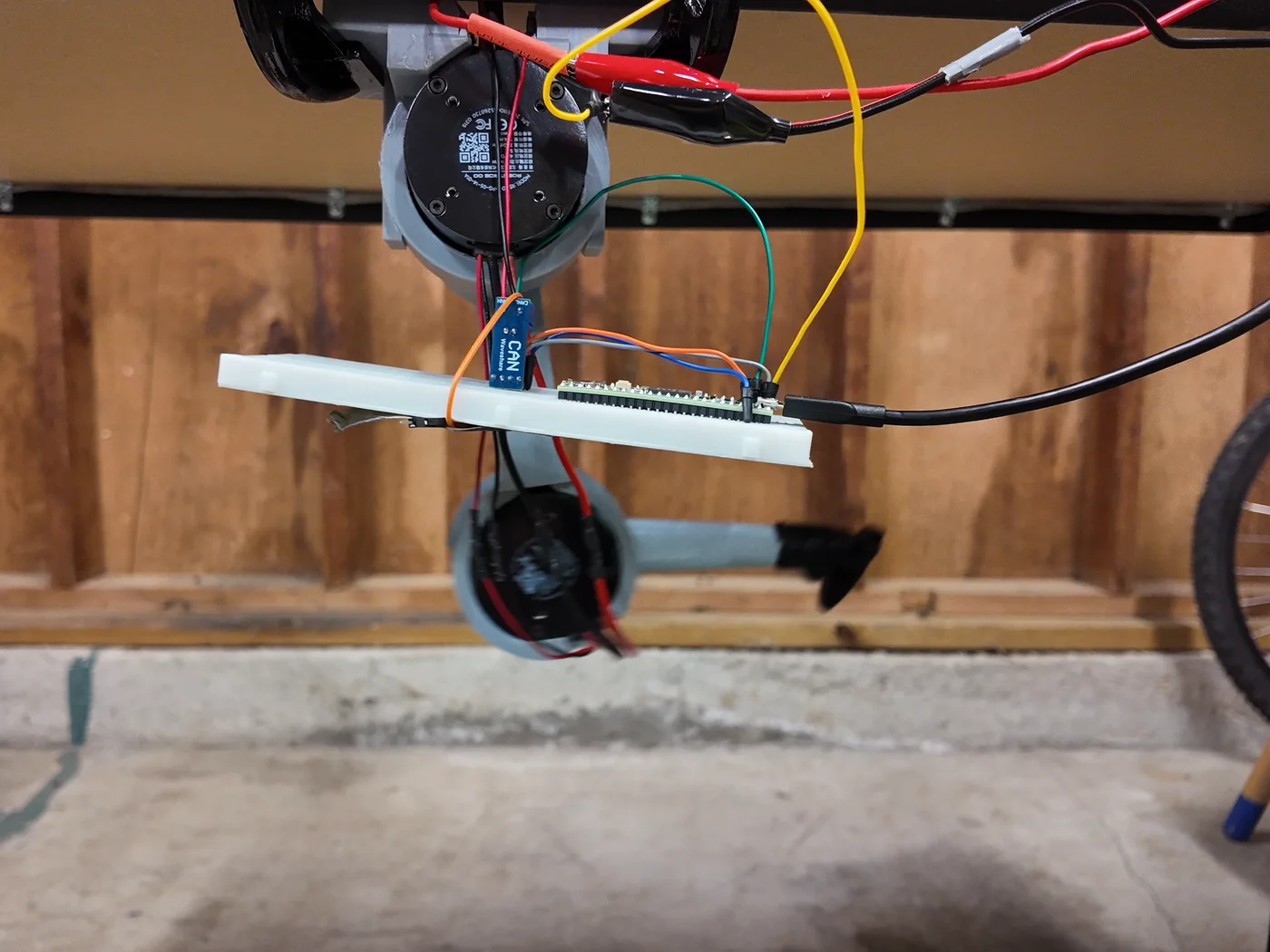
For the full leg I clamped a board to the workbench and hung the hip mount underneath it, so the leg swings freely in the air with nothing to hit. Both motors share one CAN bus from the Teensy.
![The PLA leg hanging under a board clamped to a workbench, with the Teensy and CAN board on a breadboard beside the hip motor]()
The bench rig: hip mount under a clamped board, knee motor in the thigh, Teensy and CAN board on the breadboardThe first scan only found the new hip motor, still on its factory ID of 127. The knee motor didn't answer at all. The cause was the plug between the two motors, which wasn't fully seated. After re-seating it both answered, and I gave them their permanent IDs, 1 for the hip and 2 for the knee. They kept them after a power cycle.
Then the first moves with the whole leg: the hip alone lifting the thigh 30° and back, then both motors at once. After that I wrote a simple walking motion, with the hip swinging back and forth while the knee lifts the foot on each forward swing. It ran four times for the camera, speeding up to one stride a second, with no faults and both motors at 20 °C.
![The leg swinging under the board during the first walking motion]()
The first walking motion, in the afternoon (video)Watching the video afterwards, it didn't look like walking. The hip went out to one side and straight back, and the knee folded most at the far end of that swing. I fixed the timing, but the evening video was still wrong in a different way. The thigh hung straight down and the knee stayed bent, so the shank stuck out sideways. The foot never came under the hip or anywhere near where the ground would be.
![The thigh hanging straight down with the shank sticking out sideways]()
Before: each joint moved on its own, and the foot never got near the ground![The thigh leaning back and the foot planted under the hip]()
After: the foot path is planned first, and the foot stays on a flat line under the hipThe real problem was the approach. I had been moving each joint on its own and hoping the foot ended up in the right place. The fix was to plan the foot instead. In stance, the part of the step where the foot is on the ground, the foot slides straight back along a flat line 224 mm below the hip. That's the standing height from the simulation. In swing it lifts and comes forward. The Teensy turns each foot position into hip and knee angles 100 times a second using the leg's geometry (two 140 mm links). This is called inverse kinematics.
Before running it, I checked the geometry with a still pose. Both joints moved to the standing position and held it. The front tip of the foot ended up right below the hip motor, with the foot pad almost flat, tipped down only 2 or 3 degrees at the toe. So the leg matches its own math closely.
The first planned gait used a short 40 mm step, because I had guessed the hip's range too small. I moved the leg by hand to show how far back the hip can really go, and with the corrected limit the step grew to 80 mm with a 40 mm lift. Then I ramped it from a quarter stride a second up to 1.58 strides a second. That's about twice the earlier speed, and as fast as the knee can go under the software's 6 rad/s safety cap.
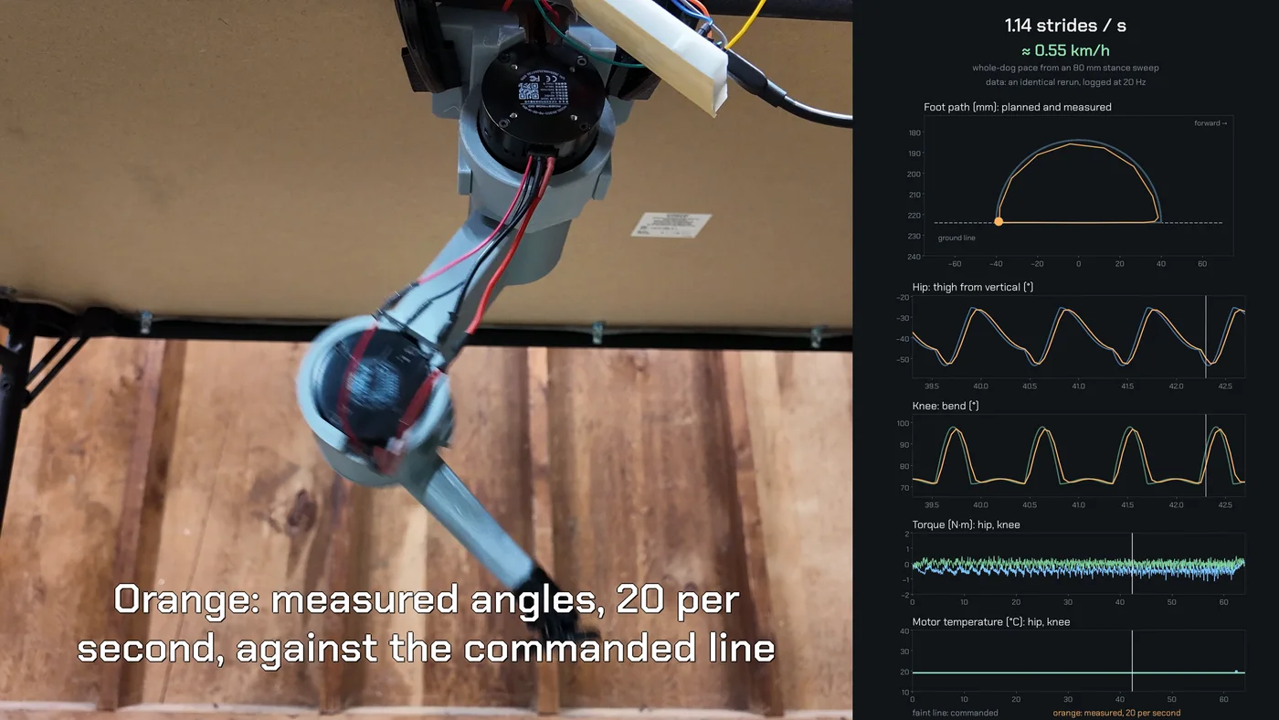
![Video frame: the leg stepping on the left, and on the right a panel with strides per second, pace in km/h, the planned and measured foot path, hip and knee angles, torque and motor temperature]()
From the gait video: the leg next to a live data panel (video)I ran it a second time with logging at 20 samples a second, so the graphs show real measurements:
- The measured foot path sits right on the planned one. At slow speed the foot was within about 4 mm of the plan on average. At top speed it trailed by up to about 17 mm, cutting the top of the swing a little short.
- Torque stayed small, about 1.2 N·m at the hip and 0.5 N·m at the knee. That's under 10% of what the motors can do, since the leg is only moving its own weight.
- Both motors stayed at 19 °C the whole time.
How fast would that be for a whole dog? Each foot pushes 80 mm back while it's on the ground, which is 60% of each stride. At 1.58 strides a second, four legs like this would carry the body at about 0.21 m/s, or 0.76 km/h. That's a slow walk. The limit is the cautious speed cap, and the motors have plenty left.
One recurring annoyance: the Teensy has dropped off USB five times so far. Re-seating the cable and pressing its program button brought it back each time. The cable or the connector is the next thing to replace.
-
Log 6: Heat test, part two: the knee housing (October 29, 2026)
4 hours ago • 0 commentsLog 5 left two questions open. The first run never levelled off, so its number was partly a guess. And it tested the bare motor in open air, while in the robot the knee motor sits inside the thigh, wrapped by a printed wall.
The same evening I ran the longer test, at 2.4 N·m for an hour. I dropped the torque from the planned 3 N·m so it would match the housing test. Starting from 14 °C, the motor climbed for 45 minutes and peaked at 89 °C. My model had predicted around 40 °C. Near the end I opened the garage door a few times, and the draught pulled it back down to 81 °C.
Why so much hotter? The model only counted the heat from current flowing through the copper windings. So I held a few torques for a couple of minutes each and read the watts on the power supply. Holding still, the motor does no mechanical work, so every watt it draws ends up as heat inside it. At 2.4 N·m it drew 9.3 W, about twice what the copper alone explains. Even holding almost nothing it used about 3 W. Some of that is the motor's built-in driver electronics. Counting the real watts, the bare motor on the stand rises about 7.5 °C per watt, more than the 4 to 5 from Log 5.
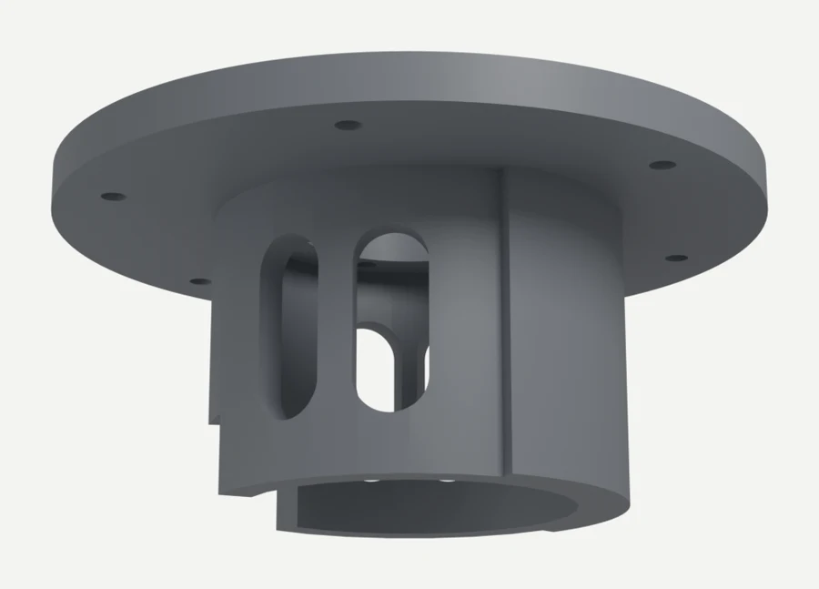
For the housing test I printed a new version of the stand's adapter in PETG with the knee wall from leg 1.0e. It has a 6 mm wall, a 1.5 mm air gap around the motor and four vent windows. Everything else stayed the same: the lever, the spring and the cord.
![CAD render of the PETG housing adapter, a round plate with a wall hanging below it with vent windows]()
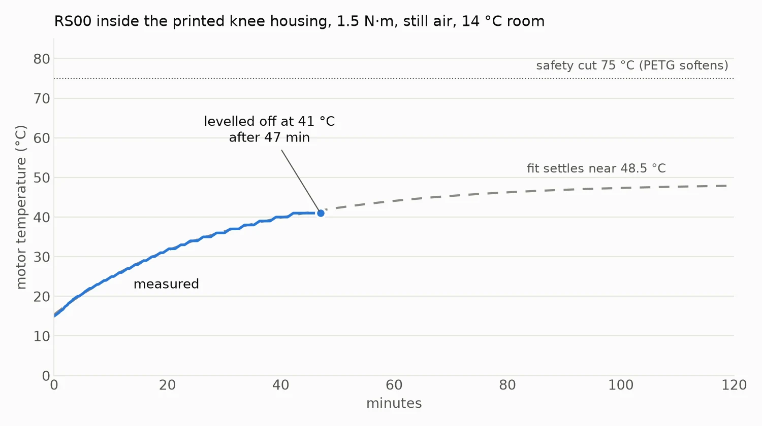
The housing adapter (CAD render): the plate bolts to the stand, and the knee wall with its vent windows wraps the motorThe bare motor already reached about 90 °C at 2.4 N·m, so this run used 1.5 N·m. I also added a 75 °C cutoff, because PETG starts to soften not far above that. From 14 °C the motor rose to 41 °C and levelled off after 47 minutes. The supply read a steady 4.5 W the whole time. Afterwards the motor case was a little warm, the plate and lever hub less so, and there was no smell and no warping.
![Chart of motor temperature inside the knee housing, rising from 15 °C and levelling off at 41 °C after 47 minutes]()
The housing run: the motor levels off at 41 °C, and the fit says it would settle near 48.5 °CThat works out to about 7.7 °C per watt, against 7.5 for the bare motor. Fitting all three runs together puts the housing somewhere between no worse and 20% worse. The plastic isn't acting as a heat sink, since PETG barely conducts heat. The vents and the air gap simply let the heat out about as well as open air does.
Then I put the measured numbers into the simulation's heat model. They pull in two directions. Over a long time the motor runs hotter than the old guess, but the motor and the plastic around it soak up more heat first, so it takes longer to get there. In still air, the knee can hold about 2.6 N·m forever before the windings reach their 145 °C limit. Walking in the simulation needs more than that at the knee, so no walking speed can go on forever. The table shows how long each leg design walks from a cold start before the knee needs a rest.
Leg and speed Knee load Old estimate Measured housing 1.0c, 0.5 m/s 4.0 N·m 9 min 20 min 1.0c, 1.0 m/s 4.2 N·m 6 min 17 min 1.0c, 1.5 m/s 4.8 N·m 4 min 12 min 1.0d (soft ankle), 0.5 m/s 3.3 N·m no limit (levels off at 122 °C) 36 min 1.0d (soft ankle), 1.0 m/s 3.7 N·m 12 min 24 min 1.0d (soft ankle), 1.5 m/s 4.4 N·m 5 min 15 min Times are from a cold start in still air at 25 °C, until the windings reach 145 °C. The current design, 1.0e, is 1.0d with lighter parts, so it should do about as well as the 1.0d rows or slightly better.
All of this is still air. A walking robot moves air over its legs, which can only help. The next run is the same test with a fan blowing on the motor.
-
Log 5: Heat test on the knee motor (October 28, 2026)
4 hours ago • 0 commentsIn simulation, the thing that limits speed and payload has always been heat in the knee motor, an RS00. The simulation's heat model starts from RobStride's tables for a motor bolted to a metal heat sink. For a knee motor inside the robot, the simulation assumes it sheds heat less well, but that part is only an estimate. Nobody seems to publish real thermal data for these motors, so the only way to check that guess was to heat one up.
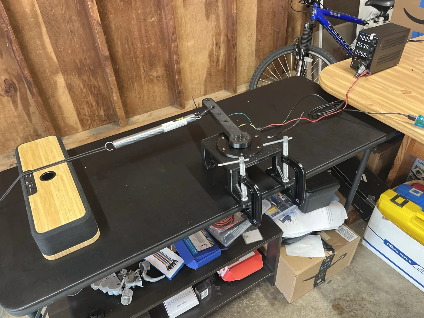
The setup reuses the stand from the torque test. This time a steel extension spring hooks onto the lever's 200 mm hole, and a cord holds its far end. The motor pulls against the spring with a steady torque plus a small wobble twice a second, a bit like a knee holding the robot up while it walks. The Mac logs the motor's own temperature sensor, and the test stops itself at 100 °C.
![RS00 in the printed stand pulling a steel spring, with the 48 V supply behind]()
The heat test: lever, spring and cord, with the supply drawing about 26 WThe first direction check moved the lever only half as far as expected. A photo of the rig showed why. The towel I'd put down as a soft stop was on the wrong side of the lever and was holding it back. With the towel moved, the lever swung the expected 3°.
The main run asked for 4.2 N·m, about 85% of the motor's rated torque. The motor went from 17 °C to 100 °C in just over nine minutes, and it was still climbing when the cutoff stopped it. The power supply showed something interesting along the way. It drew about 22 W at the start and 28 W near the end for the same torque. Copper's resistance rises as it heats up, so the hotter the windings get, the more power turns into heat.
After the run the printed stand around the motor was still cool to the touch, and only the lever's hub was a little warm. Most of the heat leaves through the motor's own case into the air. Fitting the heating and cooling curves gives the motor's thermal resistance, how many degrees it rises above the room for each watt of heat. It came out at roughly 4 to 5 °C per watt. That's close to RobStride's own heat-sink setup. But this was the bare motor in open air. Inside the robot the knee motor sits in a mostly closed printed housing with a few vents, which will trap heat. I haven't tested that yet. The simulation's figure for the housing comes from a calculation, and it lands at roughly 5.5 to 9 °C per watt, depending on the vents and airflow. Testing the motor inside a printed thigh is the next step after this one.
One run isn't enough to trust that number. The motor never levelled off, so the fit had to guess where it would have settled. The next run uses a lower torque, 3 N·m for 45 minutes, which should give the temperature time to settle on its own.
-
Log 4: Torque test on the motor stand (October 27, 2026)
4 hours ago • 0 commentsOn an earlier bench night I told the RS00 to produce a set torque, but its own sensor reported only about half that while the motor was turning. If the motor really delivers only half, the inertia I measured that night is wrong, and so is every torque the simulation assumes. The only way to settle it was to measure the torque from outside the motor.
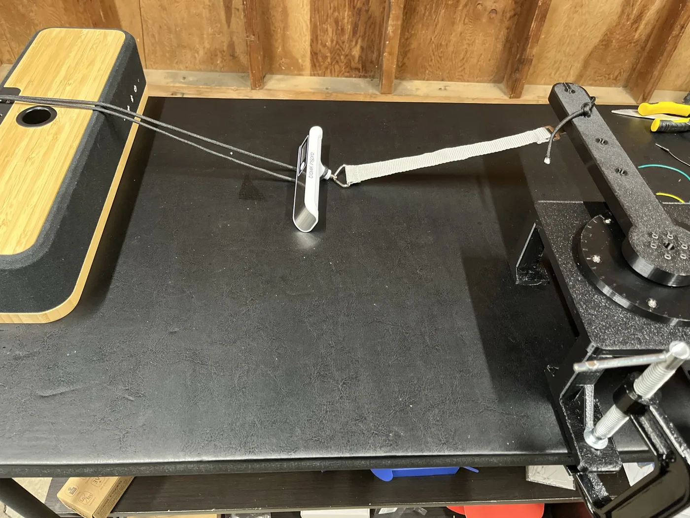
The RS00 sits in a printed stand with a 300 mm lever on its output. A strap runs from the lever's 200 mm hole to a luggage scale, and a cord ties the scale to the table. The motor holds six torque steps from 0.5 to 5 N·m. The scale reading times the 200 mm arm gives the real torque.
![RS00 in the printed stand, with the lever pulling a strap, luggage scale and cord]()
The torque test: lever, strap, luggage scale and cordIt took five runs to get a clean one. The scale freezes its reading after each pull, and the first holds were too short to read and reset it. A slack cord then let the lever swing far enough to trip the safety stop. Longer holds, a tighter cord and spoken cues from the Mac ("pulling", "read now", "reset the scale") fixed both.
From 3 to 5 N·m the motor delivered 89 to 95% of the command. Across all the steps it works out to about 98% of the command minus a fixed 0.35 N·m. That fixed loss is most likely gearbox friction while the output is held still. The readings repeated within one scale count between runs.
So the motor does what it's told. The low reading while turning was never a fault in the sensor or the motor. It comes from how a motor behaves while it speeds up. Part of its torque goes into spinning up its own rotor and gears, and only the rest reaches whatever is attached. As far as I can tell from the logs, the RS00's reading reports that remaining part, the load on the output. With only friction attached, that came to about half the command. While the motor slows down the reading even flips sign, because friction always pushes against the motion. Holding still, nothing is speeding up, so the reading and the real torque match, as they did in this test. It also means the inertia from the earlier test stands, about 0.022 kg·m² at the output, four times what the simulation was using. The simulation gets that update next, and then comes the heat test on the knee motor.
All in all, this was a good science experiment, and I learned a little bit about physics along the way. Exercises like this are really helpful for me to gradually improve my knowledge about mechanical stuff that I really haven't studied much until now.
-
Log 3: Leg 1.0 and the first printed leg (October 27, 2026)
4 hours ago • 0 commentsLeg 1.0 keeps both motors at the hip and drives the knee with a push rod, so the lower leg stays light.
Video: Leg 1.0 tour
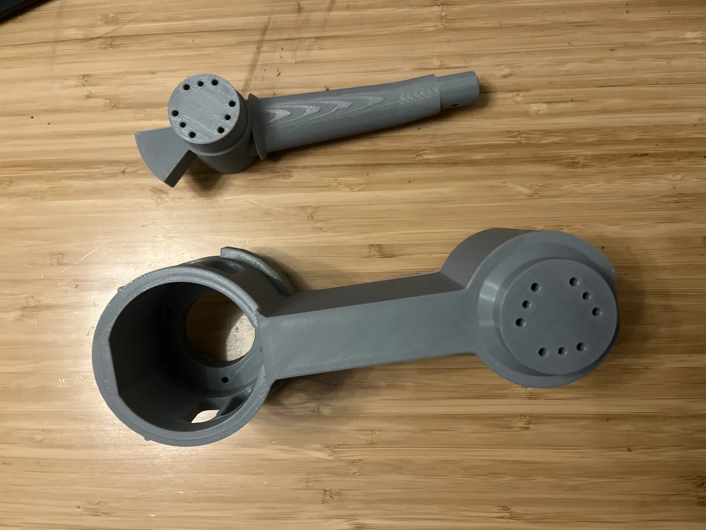
Since then the design has moved to the knee motor sitting at the knee (1.0c to 1.0e), which cuts the parts per leg from 21 to 10. The first printed parts are a fit check of 1.0e in gray PLA: the thigh with the knee-motor housing and vents, and the shank with its end-stop tab.
![Thigh and shank from above]()
Thigh and shank from above![Thigh vents and the printed shank beam]()
Thigh vents and the printed shank beamNot everything printed the first time. The hip mount failed partway through when two tall, thin tree-support trunks came loose from the bed. The fix was sturdier tree supports, wider branches and a raft that merges the support feet into one large base.
Video: My 3D printer cooked me spaghetti
Next up: the torque test on the motor stand, then a heat test on the knee motor, which simulation says is the part most likely to run hot.
-
Log 2: First motors spinning over CAN (October 22, 2026)
4 hours ago • 0 commentsGetting the first reply from a motor took three nights.
Night 1: a USB-to-CAN adapter straight from the Mac. The bus flooded and the motor never answered. I assumed the motor was the problem.
Night 2: a Teensy 4.1 with cheap SN65HVD230 transceiver boards. All three boards failed the same way. When they were supposed to drive the bus, both CAN lines dropped to about 0 V, even on a board that had never been near the motor. It seems to have been a bad batch.
Night 3: a genuine Waveshare SN65HVD230 board. It passed the line test right away, and the RS02 answered on the first ping. It was the same motor from night 1, so the motor had been fine all along. After that it was quick: a 45° move, then the RS00 on the same bus, a full turn, and a speed run that held 315 rpm.
Video: Both motors spinning together on one bus
Lesson: test the transceiver on its own first. If it can't pull the lines apart when driving, nothing else matters.
-
Log 1: Choosing motors and the first parts order (October 17, 2026)
4 hours ago • 0 commentsI didn't want to spend thousands of dollars before knowing whether the motors would do what I needed, so the first order was only enough to test them: one RobStride RS00, one RS02, a Teensy 4.1, CAN boards, and the basic tools I didn't own yet (soldering iron, wire cutters and so on). About 30 items and around $900.
I bought one of each size on purpose. The RS02 is the stronger one I expected to need at the knee, and the RS00 is the lighter one for the hip. Having both on the bench meant I could measure them before deciding how many of each the full robot needs.
LocksleyFox
A home-built, fox-styled quadruped with RobStride actuators, 3D-printed legs and sim-first design.