-
ECHO! (Echo.) (echo)
05/11/2017 at 12:55 • 0 commentsGot my second program up and running. It echos what is received over the UART. It looks for the transmitter to be ready, then waits for new data in the receive buffer, then transfers the byte in and out. First step toward a bigger interface. The bigger plan is to have a simple terminal interface where I can write bytes to specific locations in memory. And then be able to load the program counter. This will let me load a program into memory and then execute it. I figure I can copy/paste programs from my laptop. I could have my program jump back to the bootloader after it is done so I can peek/poke memory locations to check its results. And maybe put in breakpoints or something.
I would also like to get my project into Github which I've never used before. For 1) to share and 2) configuration management. It's in a good state for someone else to download and either simulate or program their own dev board. It's not the cleanest code right now, but I'd like other people to be able to take a look if they'd like. And I'd like it stored somewhere I don't think I'll destroy it. One more tool to learn, but I guess that's part of the point of the project - to learn!
0 => x"84", 1 => PCTEMP, -- move new memory page value located at 04 -> PC High Temp 2 => x"85", 3 => PCLO, -- move new memory page value located at 05 -> PC Low 4 => x"02", 5 => x"00", -- constants for new PC --UART echo 512 => UARTTX, 513 => PTRADR, -- mov UART TX status -> pointer addr reg 514 => TRASH, 515 => PTRDAT, -- jump back to 512 if busy 516 => UARTRX, 517 => PTRADR, -- mov UART RX status -> pointer addr reg 518 => x"0C", 519 => LOAD, -- load forward jump address 520 => LOAD, 521 => PTRDAT, -- jump forward if data is ready 522 => TRASH, 523 => PCLO, -- jump backward if data is not ready 524 => UARTDAT, 525 => ALUA, -- move UART data to holding register 526 => ALUA, 527 => UARTDAT, -- move holding register back to UART data 528 => TRASH, 529 => PCLO, -- jump back and repeat loop -
ALU restructuring
05/10/2017 at 17:20 • 0 commentsI think I may restructure my ALU a little bit. I originally had an A register and a result register. Writing to the result location puts the databus into the B port of the ALU and then captures the result into the result register. The problem is that the ALU has functions which don't rely on the B port. Like it has an A+1 function. So if I want A+1, I need to do a dummy write to a this register first, and then I can read out A+1. It would be nicer if I could have an A and B register instead, and then just read whichever result I want. So there's no result register - all results are available which are possible on the A and B registers. So if I want to have a simple up counter, I can just move the A+1 output to the A register and it takes one instruction. In the old way, it would take two. This would be a more elegant solution.
However, I would need to put a tri-state buffer on the ALU output which would cost me one more chip. A nice thing about the registers I've chosen is they have built-in tri-state buffers. One goal is to minimize my chip count, so I think I may hold off on this change for now. Sure some things cost me an extra instruction, but maybe that's easier to absorb than an extra chip.
-
It lives!
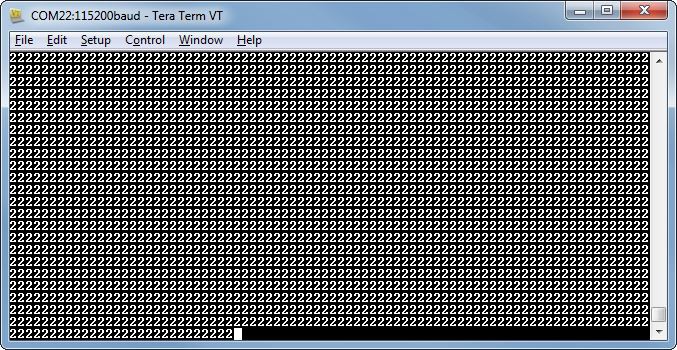
05/09/2017 at 17:05 • 8 commentsI know it doesn't look like much, but it's my first proof that my architecture is valid. After more struggles with my software tools, I was finally able to connect to the Cmod board and download. My first successful download gave me this output. There were a lot of things that needed to go right, but I guess I took care of them beforehand. I wasn't sure the clock was set right, and my UART needed to be running at the right speed, etc.
My program loaded the value 35 into ALU A, subtracted 3, and moved the result to the UART. This gives me the value 32 which is ASCII 2. I didn't have a stop to the program, so I think it's wrapping around the whole memory space and executing the code again and again. Fortunately, my program is set up so that a command of all zeroes will do nothing (MOV TRASH -> TRASH).
Next up is writing some software. I should also start thinking about how to do an assembler of sorts. This is where I get into uncharted territory for me. I've never written an assembler. I don't really want to have to worry about keeping track of memory locations for jumps or variables. But maybe that can wait for a little bit. I want to write some programs! Maybe I'll start working toward a bootloader so I can put programs in RAM over the UART.![]()
-
Synthesis successful!
05/09/2017 at 12:40 • 0 commentsFinally have no critical warnings on my synthesis. Turns out my circular reference was my own fault (not surprising). I forgot to put registers on the carry-out and A=B pins from the 74181 module. They fed straight to the databus which fed right back to the 74181. Next up is writing a piece of code which I can verify is working. I may throw for the endzone and send data to the UART first. And then when the ball bounces off the helmet of my receiver, I'll use the LEDs and buttons of the Cmod board. And probably also the GPIO pins and my logic analyzer. I may create an LED register and pass that out. It would make for some good pictures and I think people like those a lot. And prove I'm actually making something...
-
Timing
05/08/2017 at 02:42 • 0 commentsI worked all weekend on figuring out how Vivado timing constraints work. At first it seemed pretty similar to ISE, but I kept getting errors. Apparently there's a lot more to it. Input and output timing constraints seem to be required to eliminate all critical warnings. It's probably to protect against all system level timing problems. I used to just register all inputs and outputs at the pin to minimize timing paths, but I suppose this way could be better to be sure.
After many hours I figured out I had two timing constraints on the clock. I guess the clocking wizard created one which I didn't know about. Now I'm down to just one problem: the 74181 model I found is giving me a circular reference. It's a bit of a mess, so I may rewrite it now that I have a better understanding of how it works. I also haven't fully checked it, so it's possible there's a mistake. I think after I fix that, I'll be able to generate a bitstream and download. We'll see tomorrow.
-
Fork it?
05/06/2017 at 22:49 • 0 commentsI've been working on getting the computer synthesizable and ran into a snag. I thought the synthesis tool was going to be smart enough to convert the tri-state bus into a big mux bus, but it's not up to the task. At least as far as I can figure. So I have to choose to split the project into two parts - one that's synthesizable and one that represents the real components. I could keep trying to coax the tools to get it to do what I want, but I don't have a lot of confidence in that.
So I'll have to take all of my chips which output tri-state and change them to always output a distinct logic level. And then send all the individual buses into a giant mux. Considering my whole design is based on tri-state buses, then only the whole design will have to change. But maybe it's not so bad. It isn't hard to write muxes in VHDL. But there's lots of little changes. I'll have to keep a version of each since I'm eventually planning on making the discrete chip version.
-
Unique coding
05/06/2017 at 12:13 • 1 commentI've been attempting to write some simple test programs for my computer. It's kind of a different style of programming that takes some getting used to. Some things are surprisingly fast and easy and some things take a little longer. I have to write psuedocode first and then figure out how to translate to my machine code. For example, I thought one of the first programs could be a simple echo of characters from the UART back to the UART:
- ** echo characters to UART
- loop:
- wait for UART to be not busy
- move from UART data to ALU A
- move from ALU A to UART data
- jump to loop
This turns into:
- UARTWAIT:
- 00:move UART TX status -> pointer address reg
- 01:move TRASH -> pointer data reg
- ** 1 is busy which will jump back, 0 is ready which will fall through
- 02: move UARTDATA -> ALUA
- 03: move ALUA -> UARTDATA
- 04: move TRASH -> PC_LOW
I'm not sure if I can write and read UART data just yet, but I think I can. I could also replace TRASH with a memory address which holds the address of UARTWAIT.
Anyway, I was also thinking this could be made into a video game. It reminds me of the different programming style you need for TIS-100. I envision a person/robot you control by moving to different windows in a factory. Each window does a different function, and your job is to just move boxes from one to the next. Maybe it keeps track of your steps so you can replay later. Perhaps even be able to type the steps in if you prefer. All it would need is simple arrow keys and one button to pick-up/drop-off. Man, I wish I had more free time to work on projects like this.
-
UART bits
05/05/2017 at 20:12 • 0 commentsI've found an old UART transceiver I made a long time ago and put that into the project. I had to bring in a few more procedures to support it. I haven't checked it out yet, but it's connected to the databus.
I also changed how I access individual bits. I don't want a whole register just to read a single bit. So I have one driver which drives the upper 7 bits low on all bit register reads. So when I read my carry bit, it will only take a single flip-flop instead. I'll have to pick out chips to do this next.
I also put the program counter readback buffers on the bus. I've been thinking about how to do software functions, and I don't see an easy way to return from a function call without first storing the program counter in a memory location (maybe software memory stack). Two more chips...
-
RAM-out
05/04/2017 at 22:45 • 0 commentsI have the RAM pulled out of my code and put into a testbench. I also pulled out the clock and reset pins. Took me a little bit since it was wedged in there pretty good. After that, I was finally able to synthesize and implement the code. It's not quite ready for prime time yet. I still need to put in the clock manager block and I/O blocks. But the testbench still works.
I'm also going to have to come up with a short program to run to prove it's working. What better than Hello World! I figure I can store the ASCII characters in the ROM. Then have a loop which copies a letter to the UART, then waits for the UART busy to go low, then increase the pointer to the string, and repeat. Just have to get the UART working next.
-
Synthesizable
05/04/2017 at 14:57 • 1 commentI've been working on changing the code so that it is synthesizable. I was originally planning on only simulating and so I took some shortcuts. I was loading the RAM while in reset, so I implemented the ROM and put the instructions in the declaration line instead. Then I took the clock and reset lines out.
Next up is making a chip-specific wrapper for my code. I grabbed the pin-constraints file for the Cmod board from the Digilent website. I need to make a few extra modules like the clock module and a reset. And I'll want to put a few extra features in there like halting the clock and stepping the clock manually. And I'll need to pass the RAM signals out of the chip, and then make the UART interface. Then it should work!
One-instruction TTL Computer
A breadboard-able computer which uses only a single instruction - MOVE