Close
0%
0%

prism laser scanner

bringing additive manufacturing to the next level

Similar projects worth following
An open hardware fast high resolution LASER suited for Printed Circuit Board (PCB) manufacturing or 3D printing. The laser head can be used to write to a substrate. I am working on reading from a substrate.

The goal of this project is to develop a laser head for 3D printing or PCB manufacturing which uses a rotating prism and is easy to assemble.
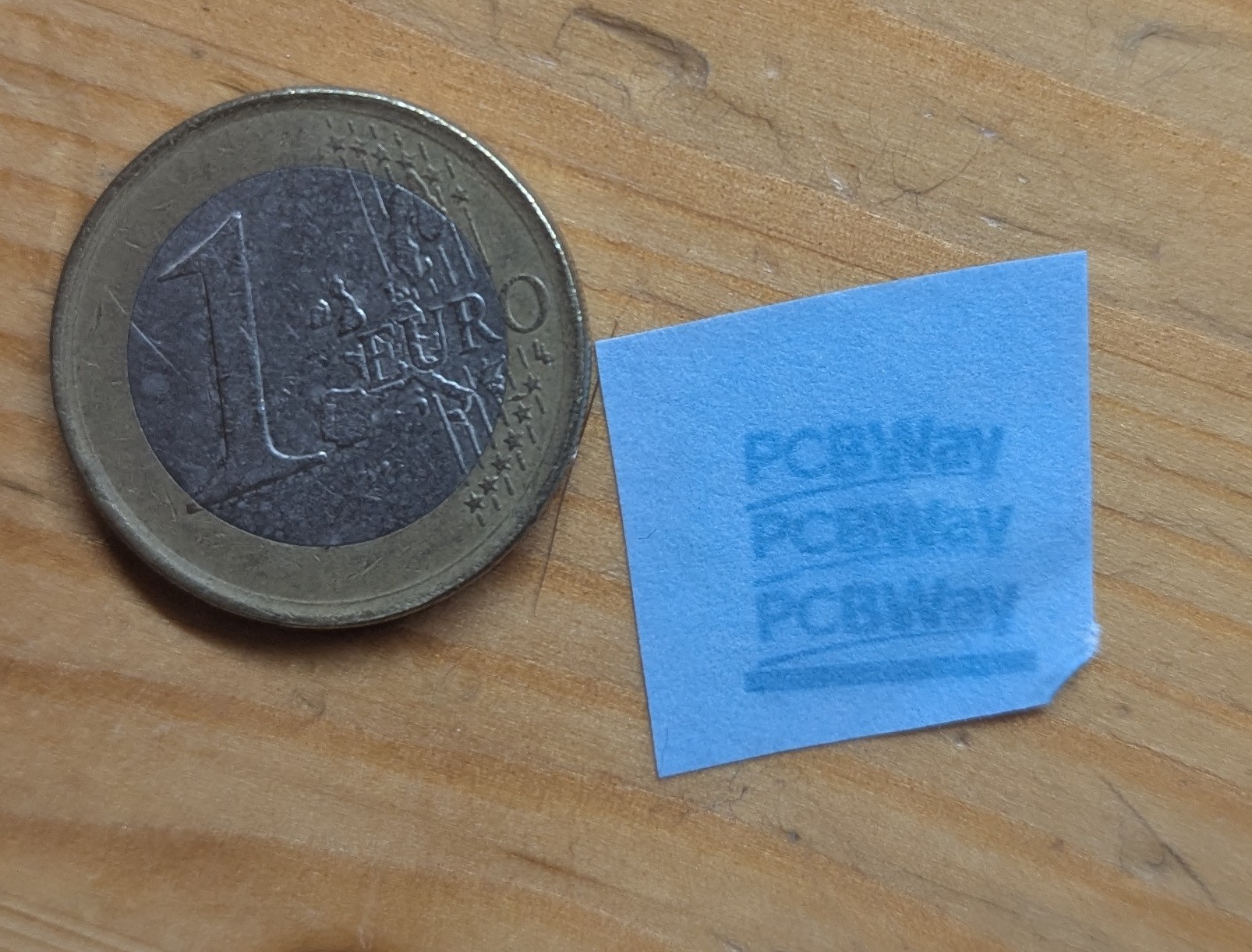
Cyanotype paper is currently used as it can be developed with water.

Specifications

Specifications are determined by exposure onto a camera without lens and OpenCV. More technical details are available in the whitepaper or the business case pitch.

  • wavelength: 405 nm
  • rotation frequency:  up to 21000 RPM, current 2400 RPM
  • line speed: up to 34 meters per second @ 21000 RPM
  • spot size FWHM: circular, 25 micrometers diameter
  • cross scanner error: 40 micrometers  (error orthogonal to scan line)
  • stabilization accuracy scanning direction:  2.2 micrometers (disabling/enabling scan head)
  • jitter: 35 microns (error parallel to scan line)
  • duty cycle: 47%
  • laser driver frequency: 2.6 MHz
  • maximum scan line length: 24 mm
  • typical scan line length: 8 mm
  • optical power: 500 mW
  • facets: prism has 4 facets
  • prism dimensions: 30x30x2 mm

Electronics

  • FPGA ICE40UP5K-SG48 with Icestorm toolchain
  • Firestarter cape  (laser driver, 3x TMC2130 stepper drivers, PWM spindle and fan control)
  • Raspberry 4

Status

An image can be exported from Kicad to SVG and converted to instruction for the laserhead. An exposure result on a printed circuit board with close up is shown below.
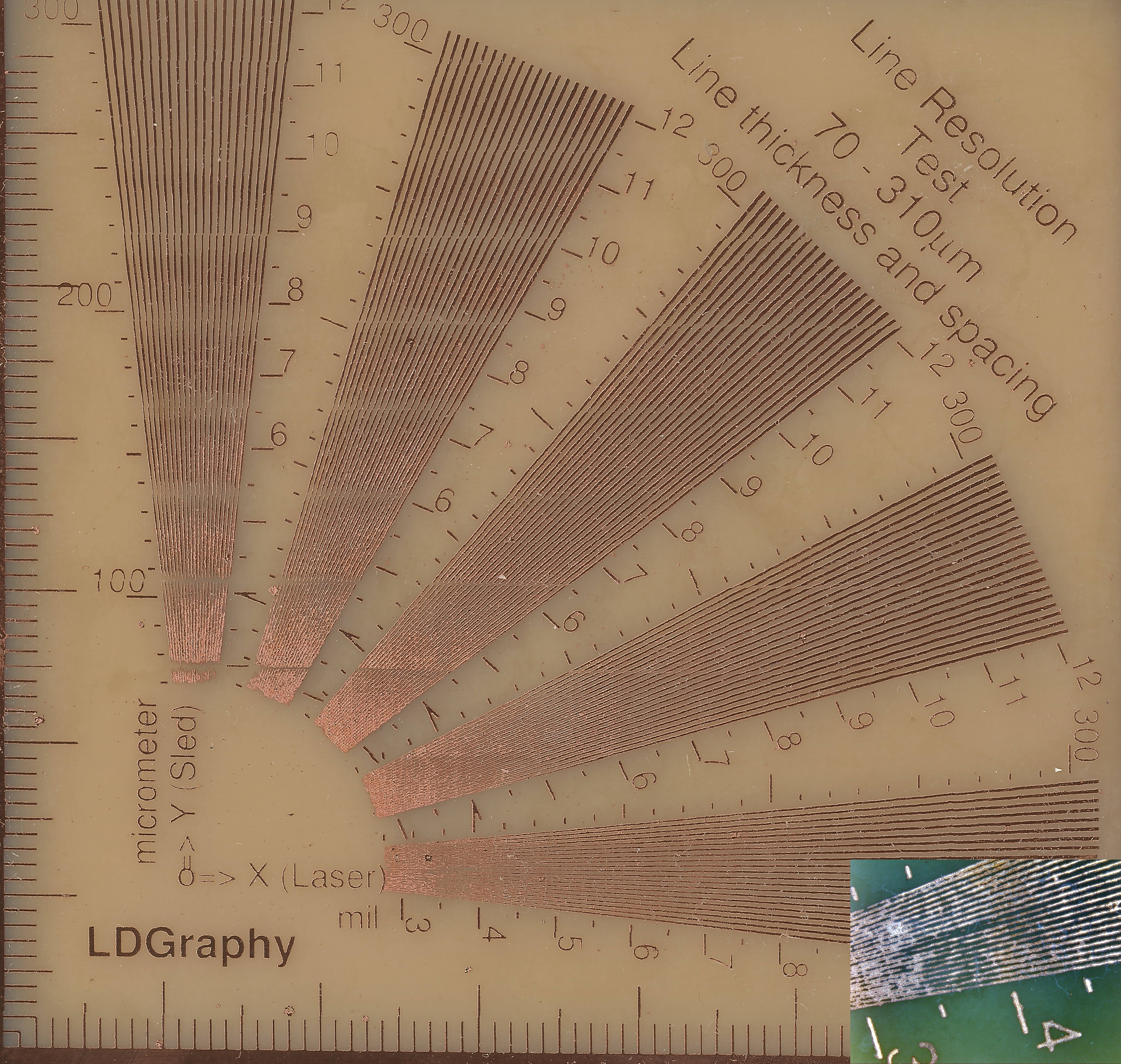
Resolution below 100 microns can be achhieved. Stitching is between lanes is quite good on cyanotype paper but still a bit uneven on PCB. Exposure below is done without cylinder lenses.

An exposure goes as follows (for the result see above).

Acknowledgement
Special thanks go to Henner Zeller for his work on LDGraphy. The electronics and software in this project helped me a lot with constructing the laser scanner, see video.
The initial idea of using a prism for laser scanning originates from Dr. Jacobus Jamar. The first system used a plurality of laser bundles in a thicker prism under an angle.  TNO, a research institute of the Netherlands, still pursues this idea, in an entity known as Amsystems.
The current gateware relies on Amaranth HDL and some components from Luna. This is the work of white-quark and ktemkin.

Software
Amaranth HDL gateware for Hexastorm
Optical design


Electronics
PCB design

Hardware designs
CAD files

Literature Research
White paper @ Reprap

Other Links
Official website

boxblend.7z

blender file used to render the main board

7-Zip - 20.82 MB - 02/16/2024 at 13:45

Download

assembly_compact.7z

blender file used in render

7-Zip - 30.82 MB - 06/29/2023 at 19:07

Download

crosscanerrorsprisms.zip

Cross scan error measurements for seven prisms.

Zip Archive - 95.89 kB - 04/04/2023 at 13:57

Download

technical_presentation_2019.pdf

Technical deck presented to selected audience. Deck does not cover LIFT, laser microscope and latest improvements on tech.

Adobe Portable Document Format - 9.11 MB - 12/10/2021 at 08:28

Preview

pitchdeck.pdf

New pitch deck of 16-9-2021, also available as video on Youtube.

Adobe Portable Document Format - 2.03 MB - 09/16/2021 at 17:50

Preview

View all 7 files

  • 1 × prism, 30x30x2 mm edges parallel to < 1 arc minute 40pcs @ 20 euro per piece @ ebetteroptics
  • 1 × ESP32-S3-WROOM2 7 euros
  • 1 × Brass Laser Module Housing for 5.6mm TO-18 LD 5 euro
  • 1 × BDR-S06J 405nm / Nichia S06J 405nm 22 euro (eBay)
  • 1 × 10x10x1 first surface PMMA mirror 2.5 euro per 20 aliexpress (alternative edmund optics #45-517 18 euro per 10 including shipping)

View all 12 components

  • Hardware Update 2024

    Hexastorm11/07/2024 at 14:55 0 comments

    Update of the hardware of 2024 using AI voice. I plan to test it in December.

  • Render of the polygon mirror motor

    Hexastorm09/06/2024 at 10:02 0 comments

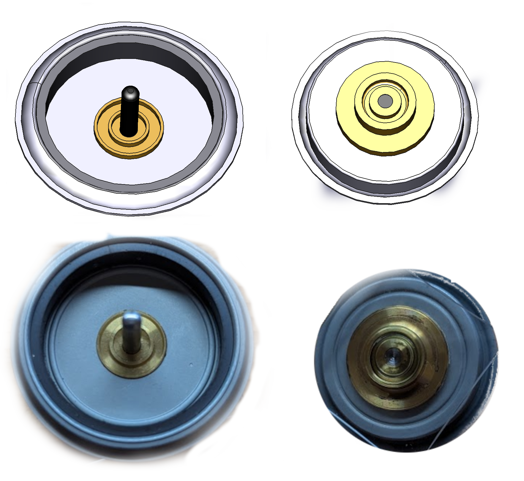
    The laser head, version 0.1, is compatible with a brushless motor. While the PCB motor is also supported, it won't be the default configuration. To accurately visualize the mirror motor, a more detailed render was necessary. The NBC3111 mirror motor and a cad  model in freecad is depicted below. Below a head is shown which supports the prism or mirror which is spinning.


  • Design Cycle Update: Extension module

    Hexastorm08/16/2024 at 17:31 3 comments

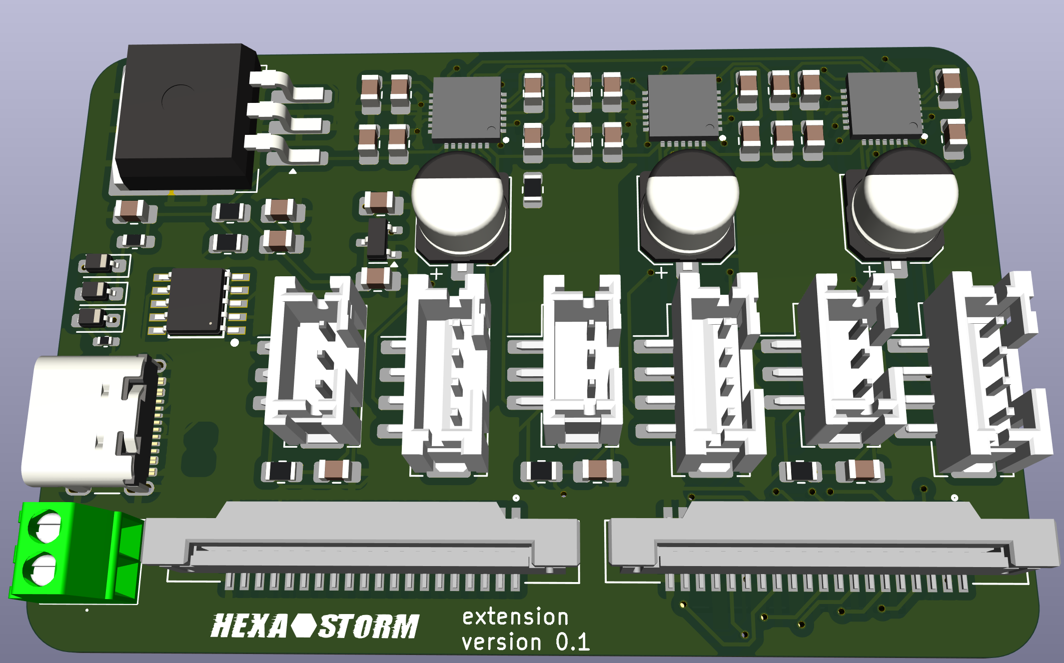
    The  extension module is mounted on top of a compute module. The female 20 pin header is not shown. Power is supplied via a USB-C connection requiring a 12V charger. An on-board converter (large black chip) reduces this to 5V for the compute board.

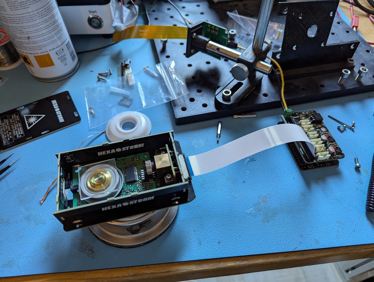
    The board has three stepper drivers TMC2208 and three end stops. A 20-pin connector interfaces with the laser head. Another 20 pin connector is free to use. The laserhead needs to move less than a FFF printer due to the polygon, as such not a lot of current for the stepper motors is required. It is assumed this is less than 1 Amp.

    Note: A USB-C connection with an FPGA for the laser head was initially considered but is currently postponed.


  • Design Cycle Update: Compute Module

    Hexastorm08/04/2024 at 10:16 0 comments

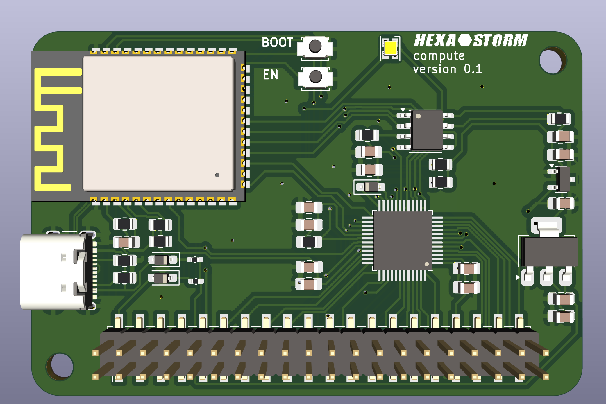
    I have initiated the next design cycle. The core component is the compute module, housing an ESP32 microcontroller and a UP5K FPGA. It's equipped with a reset/boot switch and a single control LEDs for the ESP32 and FPGA. A small memory module dedicated to storing the FPGA bootloader is also integrated. The ICE V module loads the FPGA directly from the ESP32. I keep it , as I might want to use this memory as a buffer for storing instructions to the laserhead. Board is 2 layer with mostly SMT components to keep costs low.

    NOTE: LilyGO T-FPGA ESP32-S3 is an interesting alternative but it is not fully supported by https://github.com/YosysHQ/apicula


  • Microdot webserver for laser scanner

    Hexastorm06/21/2024 at 14:11 0 comments

    I did not post in quite some time. Luckily software part is now largely finished. You can test some of the code locally in cpython.
    The webserver is quite different from Octoprint, see FLOSS weekly episode 778. I use Micropython instead of Python, furthermore I rely on microdot and not Flask.
    Taken together, I need much less resources which greatly reducing costs and deployment complexity.

  • rod based 3d printing with laser prism scanner

    Hexastorm05/04/2024 at 23:04 0 comments

    From fabbaloo, a new research paper proposes an unusual 3D printing process that uses a rod instead of a flat print plate.

    It would make a lot of sense to remove the slit and the beamer. I would use  a laser prism scanner instead. The laser prism scanner can do 20k rpm x 8 lines. It would never need to stop..

    I will get back to this

  • License changes

    Hexastorm04/02/2024 at 16:03 0 comments

    I changed the license of the software and hardware in the project. Code and hardware remain open source but cannot be used commercially unless you have a license. You are also not allowed to make clones.
    I am willing to split of parts of the code base under more permissive licenses if this leads to collaboration.

    Synopsis License Terms

    CC BY-NC-SA 4.0 Deed, you may not use the material for commercial purposes see https://creativecommons.org/licenses/by-nc-sa/4.0/deed.en  for a summary


    Motivation

    Licensing the whole project as GPLv3 limits my ability to optimize my legal strategy with relation to other rational agents. I foresee competitive pressure from Asia, given the weak European industrial base and high labor prices.
    Furthermore, I foresee increased competitive pressure and interest from the Netherlands. This has been increasing its investment in the sector of laser direct imaging.  The Netherlands is strongly against open source.
    If you now make changes, I have several options;  acquire a license from you, split of part of the work under a more permissive license which allows us to collaborate commercially or write my own code which achieves the same in another way.

  • Main board design

    Hexastorm02/16/2024 at 10:31 0 comments

    I envision the development kit consists out of two components;  a laser head and a main board.
    This post sheds more light on the main board.
    The main board can be programmed and powered via USB C. These are two "regular" USB 2 connectors. The CH224K chip is used to request 12V from the power source. The main board uses a ESP32 S3 and connects to the laser head via USB C 3.1.
    This is not a regular USB C connector. In an ideal world, you could connect to the laser head with USB C using your laptop.
    I am working towards this, and therefore I am starting to support USB C 3.1. I will share more details on this in the future.
    The main board features three stepper drivers, to move the laser head. Angled pin headers are used to connect to the end stops and stepper motors. A micro SD card reader is present for additional storage. The ESP32 S3 already provides 32 MB storage, so this should not be needed. The black box is AK-NW-84 (100x67x22m) and can be found online.

  • Laser Direct Imaging using a PCB motor

    Hexastorm01/08/2024 at 15:50 2 comments

    Finally after all these years a laser direct image using a prism and PCB motor.

    PCB motors have come a long way on Hackaday!


    On the left you see an exposure with Ricoh polygon mirror motor and on the right you see the exposure with the PCB motor.
    Both use prisms.
    The quality of the PCB motor exposure is less, still you can see the concept is working.
    I believe this is not due to the quality of the substrate but because I look for the diode between a period fraction of 0.999 and 1.001 for the ricoh motor and between 0.900 and 1.100 for the pcb motor. As such, there is much more back light for the PCB motor. This is explains the blue hue.


    @gravis
    I ran into a small issue where my stepper motors overheated. As such, I could not expose large areas.
    After reducing the current to my stepper motor the setup started working.
    I can now expose larger areas, the area is 65 mm by 65 mm. The area is exposed in 13 sweeps and one sweep is around 10K lines. I do half a step per lane. The material is quite old, had it for years and needs a lot of light.
    Possibly the chemistry is not as good as it was.

  • A promising start of 2024

    Hexastorm01/03/2024 at 15:45 2 comments

    Good start of 2024;  I made the world's first laser direct image using a prism and a PCB motor ...

    Lo and behold for the first result !

    Video with more details will follow

View all 160 project logs

Enjoy this project?

Share

Discussions

Hexastorm wrote 12/30/2019 at 15:53 point

No it wouldn't work.. you need edges polished, not the top and the bottom.
I am not shipping out prism at the moment as they r not balanced yet (working on this). I am also working on a FPGA toolchain, will post an update on my progress here soon.

  Are you sure? yes | no

Ben Wishoshavich wrote 10/27/2019 at 04:56 point

Can you recommend a specific polygon motor module on alibaba? I don't know if there are any differences and I'd like to order one. THanks!

  Are you sure? yes | no

Hexastorm wrote 10/27/2019 at 13:37 point

Yes, you should buy exactly this motor https://nl.aliexpress.com/item/32824649951.html . It uses the NBC3111 chip. I had problems with other motors. Make sure you buy at least 2, although they are quite hard to break.

  Are you sure? yes | no

Ben Wishoshavich wrote 10/23/2019 at 21:59 point

Dude, this is some pretty awesome work. I'd love to help refine some of the manufacturing and board designs, let me know how I can best help

  Are you sure? yes | no

Hexastorm wrote 10/24/2019 at 17:55 point

Thanks! There are two other people who have shown interest. I need at least 10 people to do a run as I have to buy the prisms in bulk. Turn around time would be significant. Producing the prism takes at least a month.
I am fixing the low hanging fruits at the moment. It is hard to help with these as you don't have a laser head. I am building a new one but there is still only one in the world :-).
Things you could look in to;

- a better alignment system for the laser; this uses four screws and is over dimensioned --> see my free cad design files

- a better alignment system for the cylinder lenses; the screw system is not really comfortable --> see my freecad design files

-  how do i put my state machine on an fpga; I have been looking into https://github.com/m-labs/misoc as a replacer for the beaglebone.
This task seems rather complicated but I guess this knowledge could be really help full. The statemachine now runs on pru of the beaglebone and is limited at around 2 MHz.

- how do i balance the prism; i have done some preliminary experiments but still works needs to be done. You could also try to figure this out with a regular polygon motor. Add an imbalance and try to analyze this.

- the slicer or interpolater can only be run on a computer, as it overflows the ram of the beaglebone https://github.com/hstarmans/ldgraphy/blob/master/interpolator/interpolator.py . Remove this problem, optimize the code.

In the mean time, I am cleaning up the code, building a second head and still have to do more experiments.
I am also waiting for news on the hackaday prize. That's also why I have been quiet on the blog.

  Are you sure? yes | no

Ben Wishoshavich wrote 10/24/2019 at 22:57 point

I'm wondering if there isn't a BLDC motor that could be substituted for the polygon motor, hopefully something that is more available. And then I'd need an encoder. I'll take a look at this, although I suspect going greater than 20k rpm requries air bearings and a custom design.

The rectangular prism does seem to be a challenge. I'll let you worry about that. Out of curiosity, do you know how much it'd cost for a custom order?

An FPGA should be able to handle the state machine. I'm working on the FPGA that's in the Hackaday Superconference badge, and it's got an open toolchain. It might be overkill though. The ICE40 may be better(and cheaper). I might be in the minority in that I'm not sure this is a huge priority, as your electronics are pretty cheap. It's probably a pretty significant time sync to rewrite the assembly for the PRUs into a state machine. I'd probably focus on a command and control system to interact with GCODE or something else.

 I could jump into the MCAD, but I only know Solidworks. I suspect someone else might be better suited for that.
At work, we have specifications for balancing motors for EVs. The most relevant standard is ISO1940. Let me know if that's useful for you. Usually a balancing machine is used to detect vibrations while the part is rotated. They're pretty rare and fairly expensive though. They do make some simple ones for balancing quadcopter props you could look into. Usually you have to add or remove material in a specific spot to make it work.

I already have some of the parts you've used. Perhaps it won't be as hard to duplicate some version of this as I expect.(expect for that lens).

  Are you sure? yes | no

Hexastorm wrote 10/25/2019 at 17:13 point

-  i wouldn't substitute the motors; they have been used in this application for years by a large industry. Rotating polygon mirrors are produced in the tens of thousands. Motors can handle up to 21000 RPM.  This is more than what is needed at the moment, 2400 RPM, as the beaglebone can't go faster.
- custom order is around 500-600$ and MOQ is 10. for the prisms
- Henner zeller wrote a GCODE parser for the beaglebone called beagleg; my idea is that this used and you simply flip the machine between gcode mode and laser writing mode
- never heard of this standard good tip
- all parts are easy to obtain including lenses, motor etc; the only challenge is the prism and time. You will need time :-)

  Are you sure? yes | no

rajhlinux wrote 01/01/2021 at 08:17 point

well you can count me in, i'm interested with this project

  Are you sure? yes | no

Robert Mateja wrote 07/31/2019 at 11:48 point

Congratulations on winning Hackaday Prize 2019!  (at least in my opinion)

  Are you sure? yes | no

Hexastorm wrote 08/01/2019 at 09:30 point

Robert, thank you for supporting me! Winning the prize would be amazing.  My current target is to get other people to try out the technology, I am really trying to make it more accessible. I hope I can show an improved prototype of the scan head soon.

  Are you sure? yes | no

Conny G wrote 05/27/2019 at 12:36 point

What material is the prism made from? How is it manufactured?
Can i make it in my "maker lab"?

  Are you sure? yes | no

Hexastorm wrote 05/29/2019 at 11:39 point

Prism has the following properties; 2 mm thick, 30x30 mm square,  faces 60/40 < 5 arc min, chamfers 0.10 – 0.30mm, edges Polished 60/40, top bottom polished 60/40.   You will have to discuss details with manufacturers in China over Alibaba. I made the first in a maker styled lab, a description of the process is in this log https://hackaday.io/project/21933-open-hardware-fast-high-resolution-laser/log/167433-how-to-be-transparent

  Are you sure? yes | no

Gravis wrote 02/03/2019 at 19:16 point

I'm also interested in the possibility of using a motor from a hard disk drive instead of a breaking down a polygon motor.  HDD motors are cheap to buy and (as I understand it,) contain an encoder and have screw holes which makes affixing things easier.

  Are you sure? yes | no

Hexastorm wrote 02/04/2019 at 08:48 point

HDD seem too slow.  They typically spin at 5400 or 7200 RPM.  At the moment, I can go up to 24000 RPM with polygon motor. For some applications, I would like 50000 RPM or 70.000 RPM, like the roadrunner sold by precision laser scanner. Also the motors are not too expensive, they are like 20 euros. I understand 20 euro's can still be a lot but if you look at total costs; you can better pay attention to other components.

  Are you sure? yes | no

Gravis wrote 02/05/2019 at 06:00 point

Oh, I had no idea you were planning on high speed.  Where can you get the motors in the 20 euros range?

  Are you sure? yes | no

Hexastorm wrote 02/06/2019 at 13:40 point

You can find polygon motors at alibaba (https://www.alibaba.com/showroom/polygon-motor-ricoh.html) .  The system is a proof of concept; for desktop PCB prototyping 2400 RPM is fine. If you plan to compete with Kleo https://www.youtube.com/watch?v=7R464iHaTQU . You will need at least 50K RPM.  An option would be to encase the prism and remove the air. This will reduce the drag. You could also fill the encasing with Helium as it has low drag and a high thermal conductivity.  Like the roadrunner the encasing windows would be tilted out of plane to minimize back reflections, see https://precisionlaserscanning.com/2016/03/road-runner-70000-rpm-polygon-scanner-solves-the-noise-problem/

  Are you sure? yes | no

Gravis wrote 02/03/2019 at 15:57 point

My suggestion for this project is to isolate the scanner from the 3 axis robot part so that the scanner could be made into a tool that can be changed out.  I would also ditch using BB's PRU and instead use a dedicated chip (and maybe a RAM buffer) and connect it via CAN bus.

  Are you sure? yes | no

Hexastorm wrote 02/04/2019 at 08:58 point

I intend to isolate the scanner, and design it for specific machines. I like the idea of having a dedicated chip. In the past I used a FPGA (Xula-LX25) with RAM as  bufffer. I can imagine there are even better options. The problem is that developing a dedicated board costs time, money and a lot of experience. Zeller made a very accessible code for the Beaglebone, so I went with that. You are looking at a proof of concept. It's a technology demonstrator. Anyway if you have recommendations; or some example code; feel free to share. 

  Are you sure? yes | no

Gravis wrote 02/05/2019 at 07:48 point

Considering this is a project where accurate timing is vital, I think an XMOS processor (e.g. XS1-L4A) would be a good fit.  Each 100MIPS processing unit is 100% deterministic with fast GPIOs.  I don't know the rate of data throughput you need but it may be easier to just cache to workload on a local FLASH chip than stream it.

  Are you sure? yes | no

Hexastorm wrote 02/05/2019 at 10:53 point

XS1-L4A is nice... but I rather like something with lot of support and examples... probably first gonna optimize the current code and balance my prism.

  Are you sure? yes | no

Gravis wrote 02/05/2019 at 20:37 point

XMOS stuff actually does have lot of support (https://www.xcore.com), examples (https://github.com/xcore/) and even an IDE but I somehow missed the part where you wrote that didn't want to build a custom board.  Sorry about that.  XMOS chips make it easy to glue things together since it's 99% software so it doesn't take too much skill to make a board with them.  Consider enlisting help to make a board as there is a good chance it will alleviate timing related issues.  Good luck! :)

  Are you sure? yes | no

rajhlinux wrote 01/03/2021 at 13:24 point

This is a good idea, but honestly I think the best thing is to focus on getting the precision as perfect as possible. There's no consumer grade PCB maker device that can give traces/spaces resolution down to 0.01mm. It's crazy we are still using tonner transfer and UV exposure. I'm planning to build a CNC gantry made from granite, magnetic actuators and air bearings to get the most accurate, friction free, repeatable long term PCB manufacturing with >0.7 traces and spaces. But yes, would be nice down the road to have the scanner head removed for another tool... but for now precision is priority. Precision & Resolution is the reason why this project brings my interest and everyone here.

  Are you sure? yes | no

Paul wrote 11/05/2017 at 03:49 point

You've certainly done your homework very thoroughly, and I see that in your application with very small optical cone angles (large focal ratio), the optical aberrations and field curvature appear to be tolerable.  That's great.

One question: You say that previous scan techniques require a large (and therefore expensive, you argue) f-theta lens, which must have one dimension at least as wide as the scan line.  In your approach, your polygons must be larger than the scan line length, but in *two* dimensions, making the volume of your optical element much larger.  Since either shape would use identical materials and fabrication processes in volume production (i.e. injection molding), one would naively expect the smaller element (the f-theta lens) to be cheaper.   How is this line of reasoning flawed?

  Are you sure? yes | no

Hexastorm wrote 11/05/2017 at 10:51 point

A telecentric f-theta lens requires one dimension at least as wide as the scan line. A non-telecentric f-theta lens does not require that.  In my approach, the polygon must have one dimension longer than the scan line. The second dimension is 2 mm. An f-theta lens consists out of multiple lens elements, e.g. a 3 element f-theta lens. These elements have curved surfaces. The prism consists out of a single element with a flat surface. You can't make the f-theta lens out of plastic, so you would have to injection mold quartz. I am unfamiliar with the prizes for that. Besides most likely a higher price and the fact you have to use multiple elements, you also need to worry about patents. Envisiontec patented the usage of reflective polygons; US 9079355 B2 . Finally, you need a thick reflective polygon as thick polygons can deflect collimated bundles with a large diameter and these can be focused to smaller spots.  A transparent prism uses a focused bundle and therefore typically can be thinner, which keeps the price of the bearing lower.

  Are you sure? yes | no

Paul wrote 11/05/2017 at 15:55 point

You have clearly thought about this a great deal, and have your arguments worked out well.

I wasn't considering that you might be requiring quartz.  I would have guessed even BK7 would be overkill for this application.

I mention injection molding because I look around my offices and see several laser printers.  Each of them contain a laser scanning unit with a rotating (reflective) polygon and a f-theta lens arrangement, with the final element being very large (>200 mm long).  All the optical elements of the ones I have inspected appear to be injection-molded PMMA or similar plastic.  The entire laser scanning unit must cost considerably less than $50, given the prices of the printers (all less than $200, two less than $70).  Granted, these are produced in huge volumes, but they serve as existence proof that these scanning systems with large optical elements are not intrinsically costly.

  Are you sure? yes | no

Hexastorm wrote 11/05/2017 at 16:52 point

PMMA absorbs light at 405 nm. The laser printers at your office use 800 nm and low power lasers. I use 405 nm and high power lasers. So yes; there is concrete proof that PMMA injection molded systems are not intrinsically costly. There is no proof that quartz systems are not intrinsically costly.  It's unclear what the prices of these systems would be .

  Are you sure? yes | no

Paul wrote 11/03/2017 at 13:21 point

A good variation on the usual way.  I build a few instruments based on this and similar methods between 1985-1989.  A couple of important notes:  

1. The scanned field is NOT flat: The optical distance to the target plane *increases* as the polygon rotates away from normal.  Not only is it geometrically longer, some of the increased  path length is in the high-index polygon too, increasing the path length even more.  The result is a curved focal or scan plane.  One of my instruments actually depended on this: a rotating polygon was used to tune the optical path length inside an optical resonator cavity, to adjust a tunable laser that was phase-locked to that cavity. 

2. You get some significant spherical aberration when you focus through a thick window like that, for similar reasons: the light rays at the periphery of the optical cone take a longer path to the target plane than rays going through the middle of the cone, with the result that they focus at a different depth.  For a laser at f/50 (or whatever it is), this probably isn't significant, but in an imaging system at f/2, it seriously degrades focus. 

  Are you sure? yes | no

Hexastorm wrote 11/04/2017 at 22:09 point

Paul, thank you for your reply!
A transparent polygon scanner with a single laser bundle was first patented by Lindberg in 1962.  The scan field is not flat and you can get some significant optical aberrations. A full numerical model is available here https://github.com/hexastorm/opticaldesign . A description of this model is available in the technical presentation. The result shows that in practice the scan field is flat and the optical aberrations are not significant for the current spot size and line length.

  Are you sure? yes | no

Hexastorm wrote 11/03/2017 at 11:58 point

Well this is the first comment! If Hackers are interested in transparent polygon scanning let me know :P ..

  Are you sure? yes | no

Similar Projects

Does this project spark your interest?

Become a member to follow this project and never miss any updates