-
No Updates in a Year Because ... Life Happens
10/03/2020 at 01:03 • 0 commentsWow, over a year with no updates, sorry! Plenty of good reasons, though....
April 2020 I was working like a maniac juggling 3 embedded consulting gigs. Then COVID-19 hit, and I could no longer network for new gigs. In May, I went to see a doctor about a lump in my neck that I'd had since December, which turned out to be....no kidding.....throat cancer.
Took them 2 more months to reach a conclusive diagnosis, and then I went through the horrible 7-week treatment that ran late July through early September. Weekly 6-hour chemo and radiation 5 days a week. Couldn't eat, lost 50 pounds, survived on vanilla Boost and bottled water, supplemented with IV fluids at the chemo clinic. I just started back on solid food a couple of weeks ago, but due to the radiation, everything tastes bland and I don't have much saliva, so not very enjoyable.
On a more positive note, another consulting opportunity materialized, about the time treatment ended. It's full time and runs through December. Right now it's about all I can do to just to work my gig and get by.
I'm selling my house and moving out of state next April, and will be living full time in an RV for at least a year after that. There's a ton of work to do over the next 6 months to get the house ready to sell, move 2000 miles across the country, and transition to living in the RV. Everything I own except clothes and basics will be going into a large metal shipping container that will be co-located with the RV. Once I get situated, I hope to set up a makeshift work area inside the container. This project probably won't be updated until then.
-
Machine porn
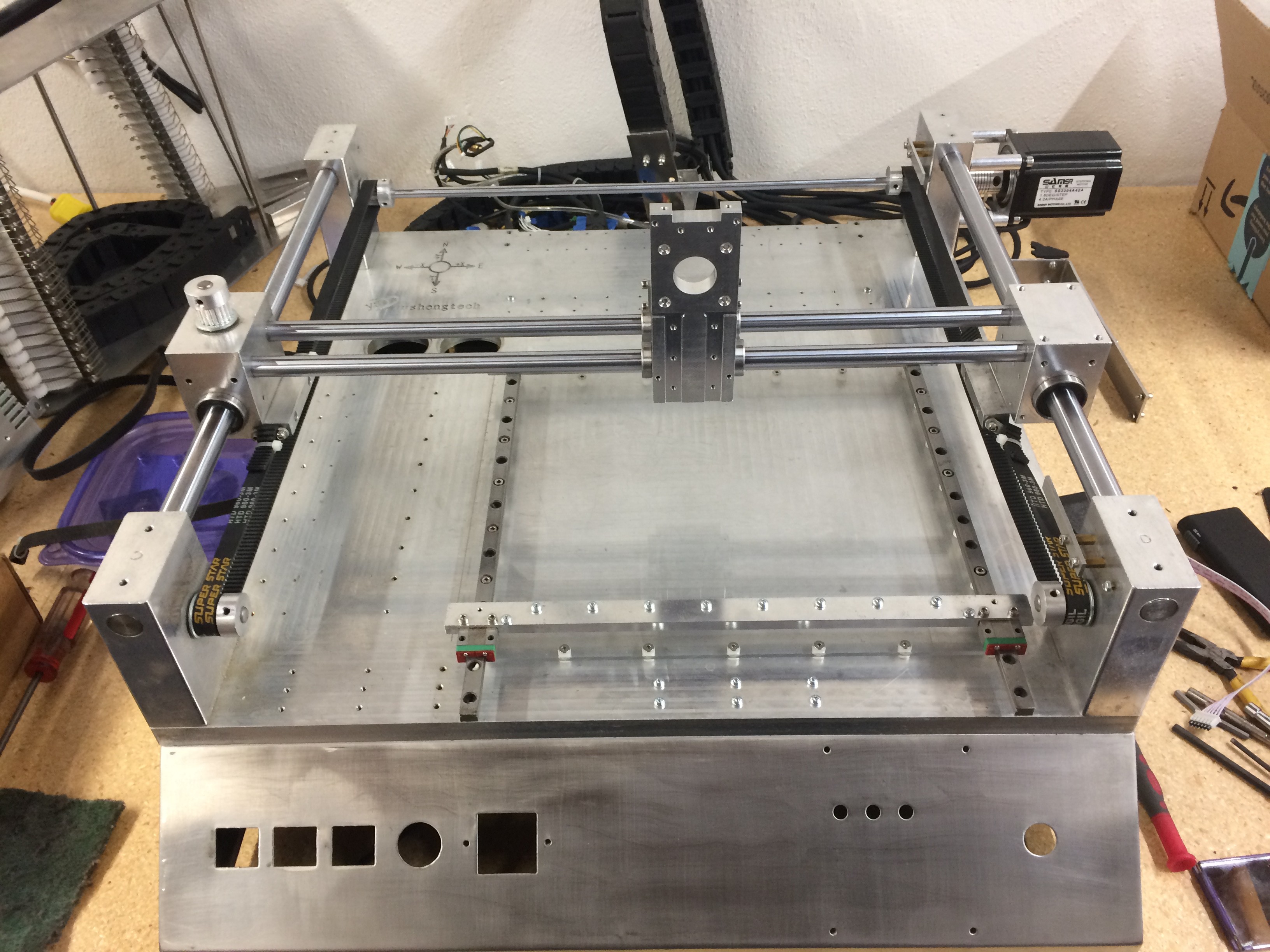
09/07/2019 at 19:13 • 0 commentsI "stripped" the machine down to the basic mechanical structure, leaving the 4 corner towers, slide rods, carriages. and pulleys. I carefully labeled the OEM cabling, but probably won't be able to reuse it, since it was cut to length with no service loops, and mummified in tons of shink tubing and tie wraps.
It was a pain to have to flip up the machine on its side to work on the underside. Putting the electronics and pneumatics to the right of the machine makes more sense to me. Meanwhile, I'll just lay out everything on the bench and connect using loose wires.
-
Slave Controller for Dual Head Assembly
09/07/2019 at 19:09 • 0 commentsSince the placement head has 3 relatively low-power steppers, an LED illuminator, limit switches, etc etc, I am looking at using a slave controller. The smoothieboard can support it over I2C or SPI (would prefer UART, but that doesn't seem to be an option). OpenPnP supports it using a sub-driver.
The slave controller would support
- A (alpha) axis - 2x NEMA8 hollow shaft steppers
- Z axis - 1x NEMA17
- top camera illumination ring using PWM
- Z limit sensors - 2x
- top camera enable
- Minimal wiring - 12V, MGND, 5V, DGND, SCL, SDA.
- Reduced cable chain weight and drag
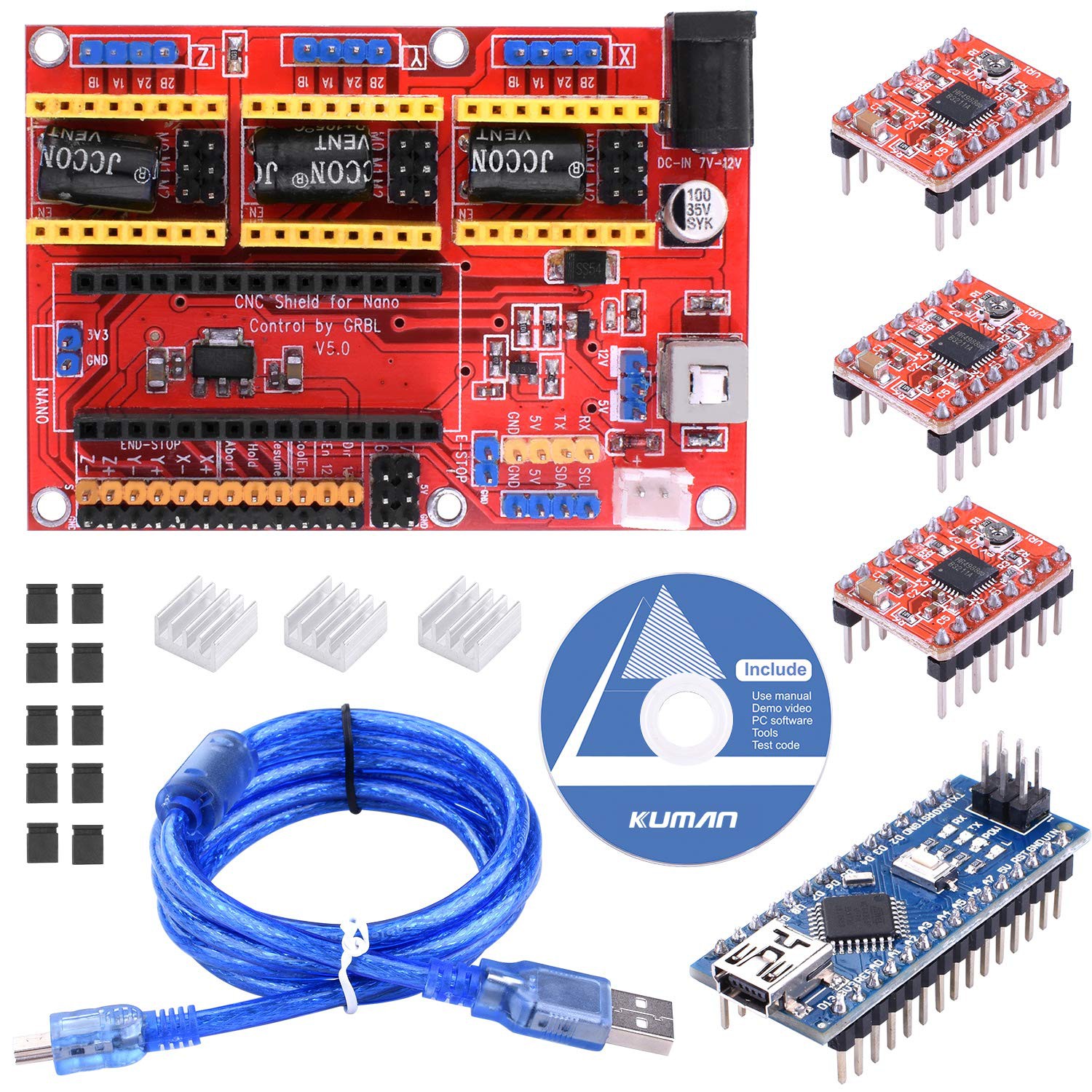
I ordered a 3-channel RAMPS/GRBL board with an Arduino nano for about $20. Looks like it could be mounted on the back side of the head assembly, and would not add much weight. Firmware is GRBL. so able to customize as required. There are about 12 I/Os available in addition to the 3 motors and 2 Z limits, so a small perfboard can be added with MOSFETs signal conditioning, etc.
![]()
-
Not Dead Yet!
09/06/2019 at 20:06 • 0 commentsWell, there went 8 months with no progress, sorry! Heading in a slightly new direction...read on.
I picked up some 4x4" aluminum bar stock from ALRECO with the intent of making a whole new head assembly to work with the Juki nozzle and longish quick change adapter from Betz Technik. Then I spent some time learning Fusion 360, then I got busy with...uhh, actual paying full time work. Gotta make hay while the sun shines.
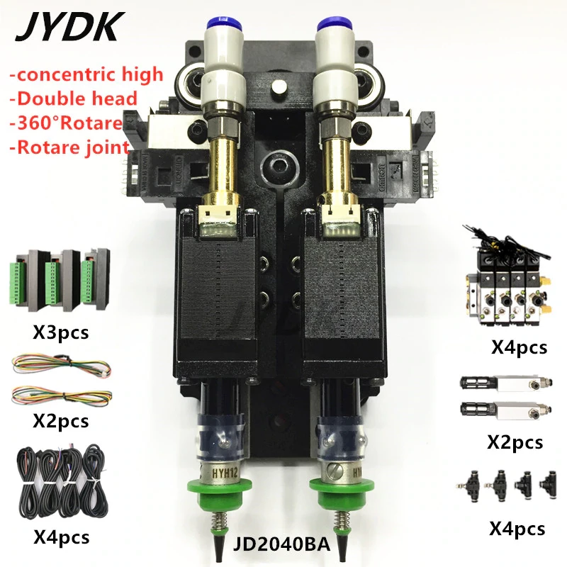
However, I just recently had a potential consulting client who desperately needed some SMT assembly work done, but couldn't say "yes" since the machine is disassembled. Re-inspired by the utility of having a working placer, I looked into buying a new head assembly with Juki nozzle support. I decided instead to buy a dual head assembly from AliExpress. I expect there will be some minor machining required to make it work, but nowhere near as ambitious as making the whole thing out of raw stock. The new head assembly will arrive around the end of September.
So now the to-do list looks like this:
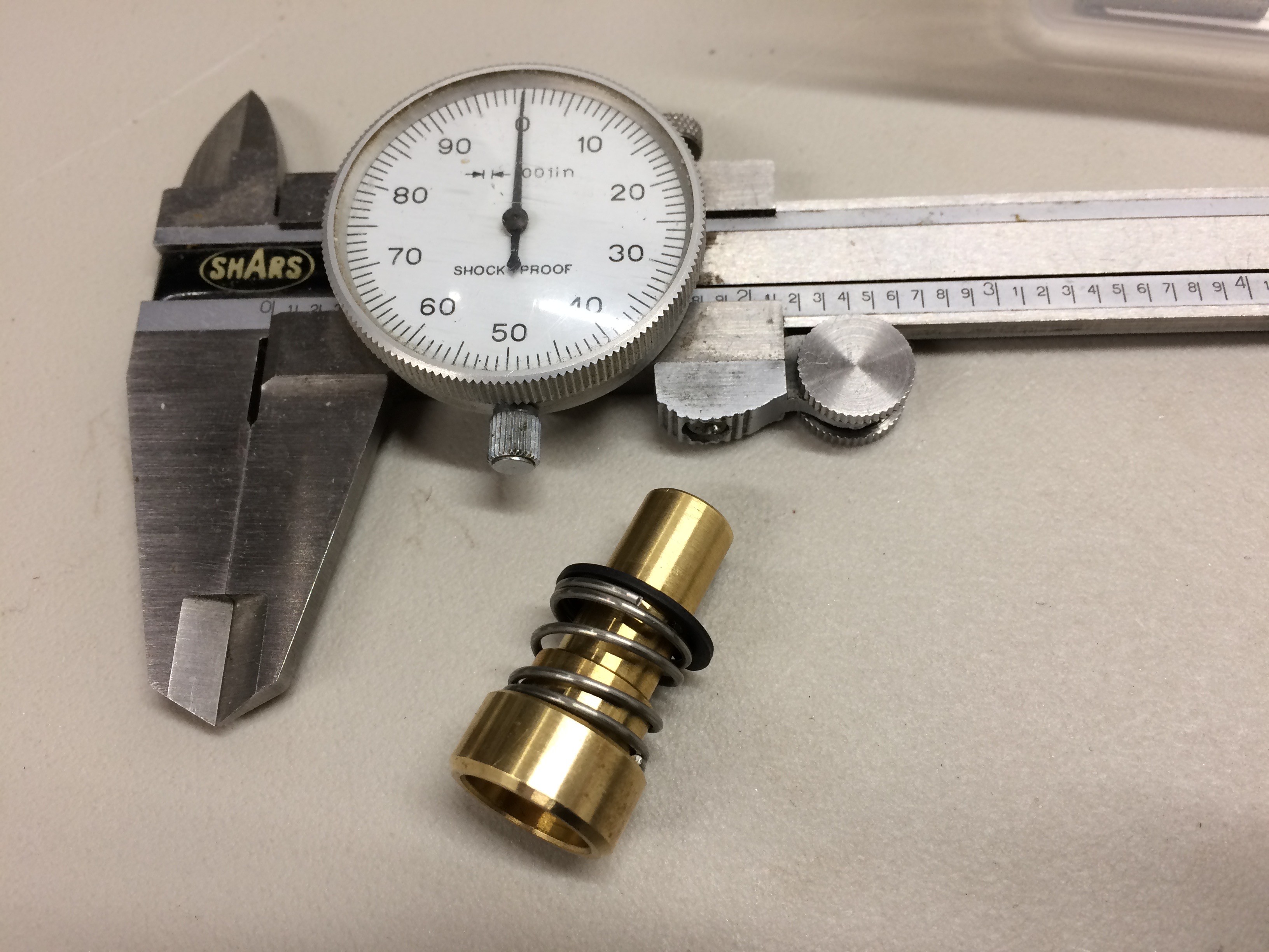
- The nozzle adapters included with the new dual head don't appear to support quick change, so I have ordered a pair of spring-loaded Fuji quick change adapters from Betz Technik. That leaves the first one as a spare.
- Mount the new dual head assembly to the existing head block, replacing the original head and drag finger, and adapting the head block as needed to achieve the correct height for the quick-change adapters.
- Top camera - design and 3d print mount, and design or adapt an illuminator.
- Bottom camera - design and 3d print mount to work with existing illuminator.
- Juki nozzle quick change holder
- Visual pickup area or tray, for using top camera to pick from cut tape and loose parts.
![]()
-
Status Update for December 2018
12/22/2018 at 02:47 • 0 commentsI've been MIA from HaD since early this year, so I wanted to give a status update to let people know that I have not abandoned this project.
As mentioned in a previous log(s), the big obstacle I encountered was adapting the pickup head to work with the Juki nozzle and the snazzy clicky nozzle adapter. I was hoping to get my 6040 CNC machine working well enough to cut metal to build something.
The 6040 still isn't working, but the big exciting news (at least for me) is that I now have in-house machining capability! A mini-mill with 3 axis DRO, a 7" mini- lathe, a horizontal band saw for rough cutting metal stock, and all the required tooling.
Back in the late 90s/early 00s, I had access to a full-size mill and lathe, and was able to gain some experience making very simple parts using Al, ABS, and brass. So, I'm not a complete noob, but in the ensuing years, I've been doing mostly embedded software, so definitely need some time to refamiliarize.
Hopefully be able to make some progress on this project very soon now.
Meanwhile, please follow and comment!
Planned upgrades:
- Redesign pickup head for dual Juki nozzles, eliminating the drag feed.
- Juki nozzle holder to allow machine to select and mount different nozzles with no interaction
- "Smart" feeder system that detects the end of the components, throws a system fault, and allows hot-swapping the feeder and continuing the placement job.
- "Visual" feeder area using top camera to identify and pick cut tape and loose parts
- New camera mounts and illumination
- New control electronics (might not be a Smoothie)
---------- more ----------I want to redesign the pickup head to support two Juki nozzles. Primarily because it would double the placement throughput, but also because I don't like the existing design with the offset rotating actuator and spring loaded return. I would like to use a belt drive to get more precise control over the Z travel. A redesign would allow the freedom to "do it right".
I also need to design and fab mounts and LED rings for the two new USB cameras.
Since the new pickup head design will eliminate the drag feed pin (which uses the other half of the head), I would also like to rethink the feeders. Two popular approaches for this are an independent feeder-per-component, or an indexed common feeder. I don't like the indexed approach because it adds layers of mechanical complexity and motion control, plus control software has to coordinate the indexing motion based on the component width. The feeder-per-component approach "hides" the complexity and can scale to support as many feeders as can be physically fitted. So, we have a design requirement to add feeders, each incorporating an embedded micro which suggest using a multidrop serial bus to signal. This opens up the possibility of "smart" feeders that can be hot swapped to replenish the component feed while a job is running. With a few carefully placed optical sensors, the feeders could detect missing components, end of reel, and perhaps even estimate the number of components remaining on the spool.
-
Status Update
01/19/2018 at 19:45 • 0 commentsIt's been quite a while since the last update. Sorry about that, but life intervened and I had to deal. I'm hoping to get back to work on this project within the next month or so, so stay tuned!
-
Status Update
07/11/2017 at 21:02 • 0 commentsI think I have everything I need to move forward on this project....except time. I've been focused on my CNC project https://hackaday.io/project/25564-grbl-powered-6040-cnc-mill. I need the CNC to make various parts and mods for the PnP, so need to finish it first. Hopefully wrap that up in a week or so.
Regarding the mods to the PnP head assembly to accept the Juki nozzle changer, I have identified a couple of approaches that should work. One is easy, the other is a bit more involved, but arguably better.
The simplest approach is to just remove the bottom section where the existing bearing/nozzle adapter were fitted. Rough cut on the bandsaw, and surface on the CNC.
The other way is to open up the round hole in the bottom section so that the Juki changer can fit through it. Then (assuming there is enough material remaining) add a support bearing which should help minimize nozzle runout.
Nozzle runout is a concern. The Juki changer secures to the stepper motor shaft with a single set screw, so any slop in the fit will move the nozzle off center. Plus, any angle between the motor shaft and Juki changer will cause the nozzle end to be off center. Ideally, it needs to be an interference fit, and the axial alignment needs to be very precise. Adding a support bearing somewhere along the length of the Juki changer would help minimize that.
-
Juki nozzle quick-change adapter
06/29/2017 at 00:11 • 0 commentsFinally received the Juki nozzle quick change adapter! Next task is to work out the details of how to modify the PnP head to incorporate this, hopefully without losing any component height.
![]()
-
Hacking the Logitech C270
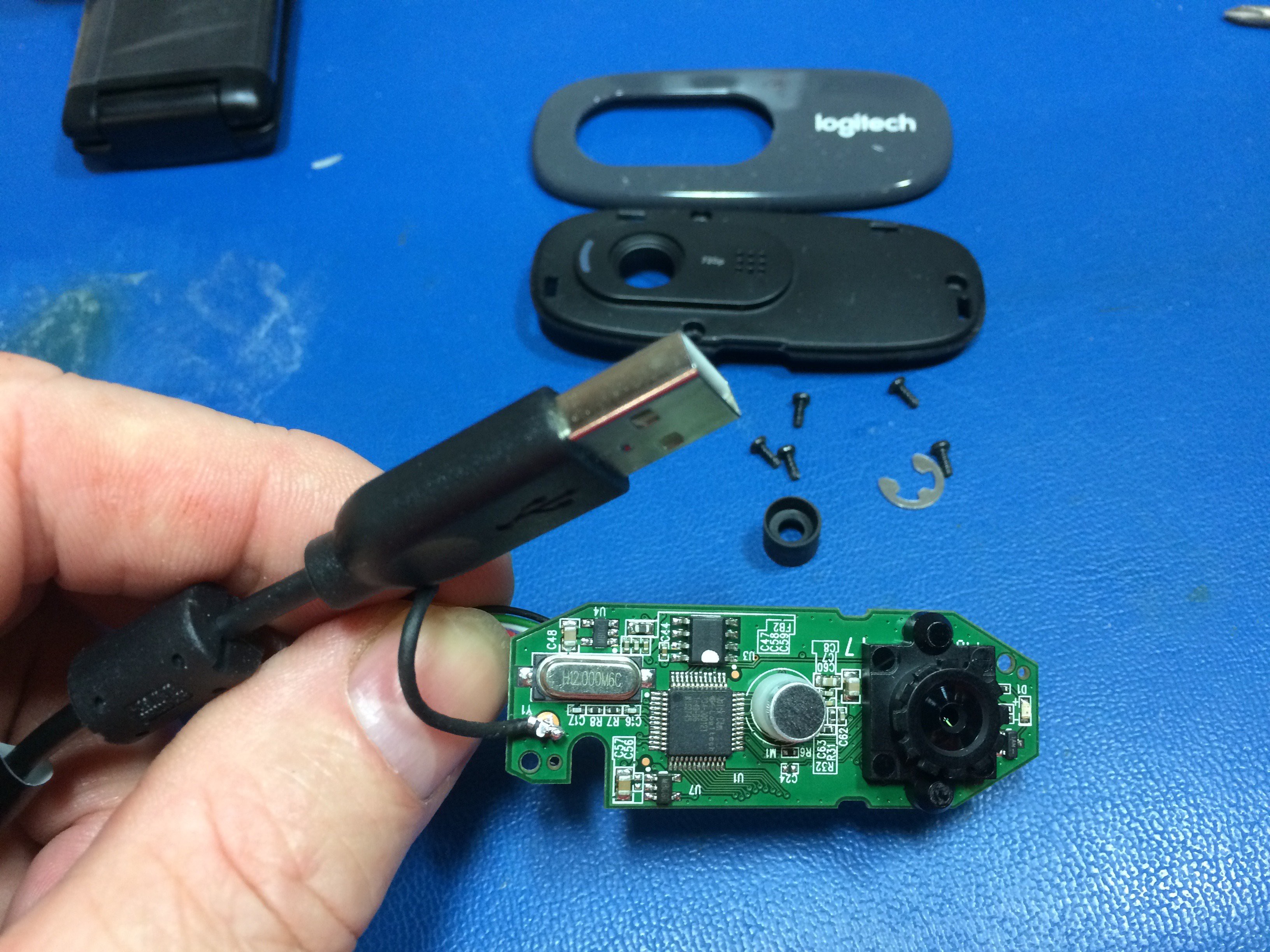
06/15/2017 at 04:53 • 0 commentsGetting the board out of the housing was dirt simple - snap off the cosmetic face plate, remove 3 screws holding the front, remove 2 smaller screws holding the PCB, unplug the connector, desolder (or snip) the shield wire, PCB lifts out. Remove cable retaining clip, pass connector out through the cable entry hole, and reconnect cable to PCB.
![]()
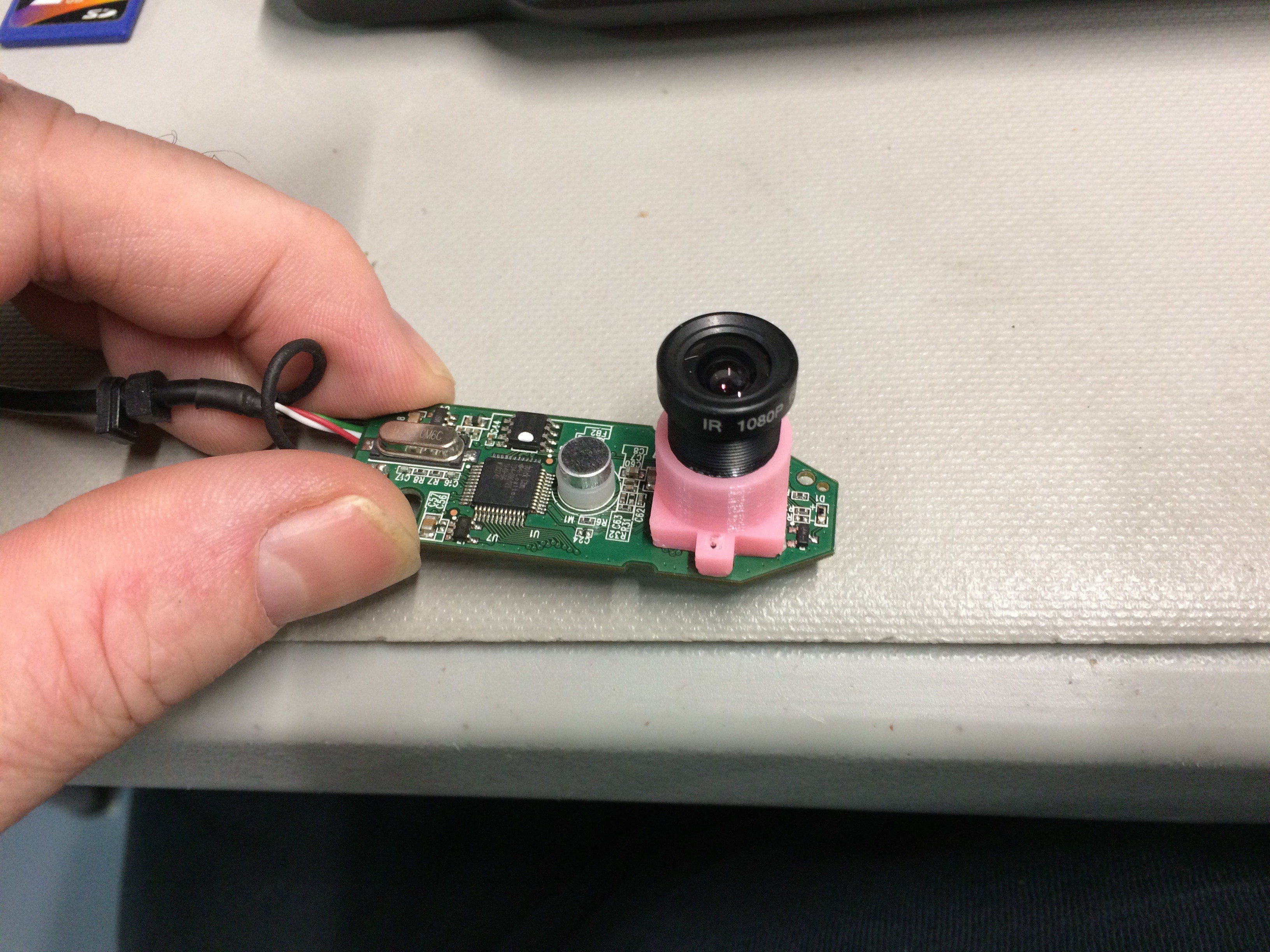
There was a blob of hot glue on the lens thread, knocked it off and the lens was adjustable. I was able to get 3" and 1" working distance into sharp focus. Larger working distances are possible.
I printed the M12 lens adapter and mounted it to the camera. I found that the pink PLA leaks light and ruins the contrast, so I'm going to reprint using black ABS. Meanwhile, I wrapped it in electrical tape. Here's a link to the lens adapter on Thingiverse.
![]()
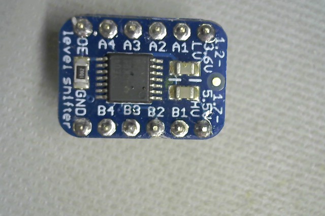
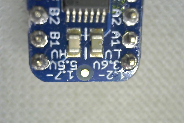
The below pics were taken in PhotoBooth while holding the camera with my hand, so they are a little fuzzy from my hand movement and also not quite parallel to the object plane. With the right M12 lens, this will make a pretty decent down-looking camera.
![Logitech C270 at 3" working distance]()
![Logitech C270 at 1" working distance]()
-
Added SSD to Macbook Pro
06/14/2017 at 23:51 • 0 commentsMacsales had OWC 60GB SSD on sale for $49.99 with free shipping, so I bit.
Hot Hot (Yushengtech) SMT50 OpenPnP conversion
Refactoring the SMT50 to work with OpenPnP
 Darryl.N