-
2017-08-09 (W) Pi0 Laser Tag PiTagErrUs
08/17/2017 at 16:58 • 0 commentsThere were not enough pipes for all the parts that had been printed and purchased. It would have been possible to simply build fewer taggers but it seemed logical to have spares and enough pipes for all the parts. A five foot (1.5m) length of ABS pipe was purchased and cut into four equally sized pieces. Masking tape was applied to each side so the center lines could be marked. This time, the TOP and BOTTOM were clearly labeled along with the FRONT and REAR.
Cut pipes with masking tape markings
The hole locations were marked with a marker and the hole diameter was written on the tape. At the ends where the handle and foregrip were going to be cemented, a knife was used to score the plastic. After the tape is removed, that line can be used to attach the handle and foregrip in line with the tagger. The holes were drilled, some as large as 30mm across and all the tape was removed.
Marking hole locations and center lines -
2017-08-08 (Tu) Pi0 Laser Tag PiTagErrUs
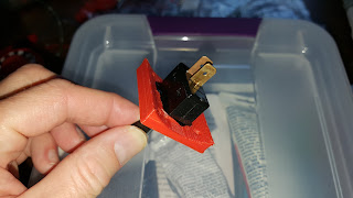
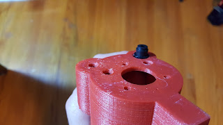
08/17/2017 at 16:57 • 0 commentsOne of the new switch adapters and a switch were selected for the first try. The shortest, pistol-style, tagger was selected because it would be the least amount to lose if this design didn't work. Medium Black ABS Cement was applied to the switch threads before it was pushed through the adapter plate. There was lots of extra cement on the plastic but it was all internal so it wouldn't be visible on the tagger.
Cemented switch
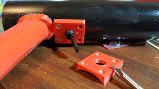
All the adapters were drilled with a countersinking bit so countersunk screws could neatly attach the plate to the pipe. The pipe was drilled with a small bit and short screws were inserted at the corners of the adapter.
Attached adapter plate
Once everything was mounted, the trigger was tested. Even though the cement had only been drying for an hour, the stability was good and the trigger tested well. The most notable problem was that the trigger and handle were far apart. Someone with small hands or short fingers may have trouble pulling the trigger.
Trigger testing -
2017-08-07 (M) Pi0 Laser Tag PiTagErrUs
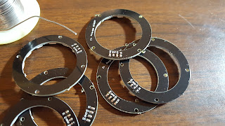
08/17/2017 at 16:57 • 0 commentsLight rings for the user-end of the tagger were tinned on their terminals. Six rings were soldered for the taggers being made. Six butt stocks were available so it seemed logical to have six light rings available as spare parts.
Light rings with tinned terminals
Wires were soldered to each terminal with no regard to wire color. The color coding will be arranged when they are attached to the control board. Wires for power, ground and LED data were kept uniform because power and ground were tapped off the same terminals.
One soldered light ring
When all six rings were soldered, none of the wire coloring matched the other models. This should not be a problem but sheets will be printed and included with each tagger which explicitly defines the wire colors for each individual tagger.
Stack of six soldered LED rings -
2017-08-06 (Su) Pi0 Laser Tag PiTagErrUs
08/17/2017 at 16:56 • 0 commentsThe switch adapter, which allowed a momentary automotive switch to act as the trigger, had been problematic due to the poor quality of the switches. When the switches were purchased, the plastic nut would not mate reliably and that would cause them to loosen when the switch was pulled.
Previous switch adapter
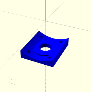
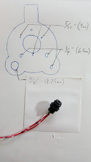
The model was revised so that the switch could be glued to the adapter but in such a way that if the switch ever failed, it could be removed from the tagger without destroying anything.This requires a larger hole to be drilled in the pipe and it may require more clearance from the handle.
Revised model for switch adapter
Four models were printed in the typical red filament and the prints came out well. Most of the switches purchased in the last year have been of low quality and this type of adapter will be needed but in the past, other switches have only needed the smaller version. When the final model package is released, both models will be included.
Four printed copies -
2017-08-05 (Sa) Pi0 Laser Tag PiTagErrUs
08/17/2017 at 16:56 • 0 commentsWork on the PiTagErrUs resumed by adding parts to the forward array. All of the LEDs were held in place by pushing them partially out of the holes, affixing the plastic LED clips then pushing the clip into the hole where they would lock in place.
LEDs being affixed into their holes
Four forward arrays were completed. All the components, screws, lenses, and LEDs were attached. It should be noted that the holes drilled for the LED holders were 9/32" (7mm) which was two standard drill bit sizes up from the 1/4" (6mm) bits used previously.
Components and lenses mounted
Infrared sensors were glued to the front of the forward arrays with ordinary super glue then held in place with rubber bands while they dried.
Sensors glued in place -
2017-07-30 (Su) Pi0 Laser Tag PiTagErrUs
08/17/2017 at 16:55 • 0 commentsAll the wires and crimp-ends for the reload buttons and triggers were gathered. Each component used a different size of crimp end. The triggers, automotive switches, used 1/4" (6.3mm) quick disconnect ends while the reload button, arcade buttons, used 0.11" (2.8mm) crimp terminals.
Assortment of parts
All the wires were stripped at both ends. One end would be placed under the screw terminals of the control boards while the other end was given a crimp end. The thin metal didn't work with my crimping tool so additional compression was needed to hold the wire in place. Green wires were used for the reload button and black wires were used for the trigger. Since these were not polarity specific, no mindfulness was given to how each wire would be used on the hardware.
Crimped wires -
2017-07-26 (W) Pi0 Laser Tag PiTagErrUs
08/17/2017 at 16:53 • 0 commentsA mistake was made when drilling the holes for the laser modules. All the holes were drilled much too wide. In fact, the laser modules wide base could fall right through the hole while the intention was to make them only wide enough for the narrow top to pass through.
Ill-fitting laser module
The drilling index was corrected with the appropriate imperial and metric measurements shown. The incorrect measurements were covered with a note showing the new measurement.
Correct hole-size index
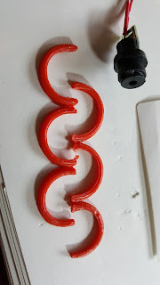
To make fixing the holes easier, a small model was designed which would print a collar that would fit around the laser module so glue could fill the rest of the space between the forward array and the laser.
Collar model
The next thing to go wrong was that I entered the diameter of the laser module instead of the radius so the models printed twice as large as I needed. Fortunately, the print time for six collars was less than six minutes.
Wrong size
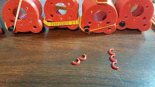
The model was corrected and more than enough collars were printed. Eight were printed in less than five minutes. Before 3D printing, this probably would have necessitated a trip to the hardware store or at least a drill press and small workshop.
Correctly sized models
All the laser modules were installed and held in place with rubber bands. E6000 adhesive was used to fill all the gaps. These lasers will not be positionable so their accuracy won't be reliable while playing laser tag.
Mending forward arrays -
2017-07-25 (Tu) Pi0 Laser Tag PiTagErrUs
08/17/2017 at 16:52 • 0 commentsMore sensor boards would be necessary for the taggers being built. Eight PCBs and components were gathered. These would probably be put inline with light strips right on the sides of the taggers. The steps for assembling these sensors in an efficient way was eventually found by doing very small procedures on all the boards before moving to the next step, similar to factory work.
Eight sensor boards with long leads
In the end, ten sensor boards were assembled with the full number of infrared sensors, four, on each board. Parts for four taggers were being assembled but there were enough parts for a fifth tagger already built but not enough sensors.
Assembled sensor PCBs -
2017-07-24 (M) Pi0 Laser Tag PiTagErrUs
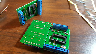
08/17/2017 at 16:52 • 0 commentsThree custom circuit boards were populated. On-hand components made it a fast process because time was not spent searching for the correct components.
Three circuit PCBs
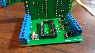
Components like the three-position screw terminal and the twenty-four-position IC socket made it unnecessary to cut down existing components to go in their place. Before, long header strips had to be cut down to make a socket for the Arduino and two-position screw terminals had to be cut in half to make a third terminal.
Close-up of boards -
2017-07-23 (Su) Pi0 Laser Tag PiTagErrUs
08/17/2017 at 16:51 • 0 commentsA list of components and wire colors were made based on an old color scheme. This version included a second set of wires for the second flashlight LED. The first version assumed the flashlight LEDs, two bright white LEDs, would be soldered together right in the array but it seemed easier to wire each light individually. Wire colors were based on some surplus multi-conductor wire, Belden 9948, a twenty-five conductor wire which could be salvaged for twenty-five wires with unique color codes on each wire.
Color coding for forward array components
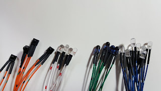
Each component had its leads trimmed and the color-coded wires were tinned so they could be soldered together. Once the wires were all soldered to the components, it was each to check for inconsistencies by comparing the components to one another. Only one LED had its leads soldered backward but this was easily remedied. Shrink tubing was used on each lead to protect them from shorts.
Components with soldered wires and shrink tubing
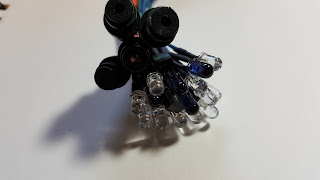
Only the laser modules didn't get shrink tubing. They had enough protection and they were uniquely sized so shrink tubing was unnecessary and impossible. For the evening, there were thirty-four wires stripped and tinned, leads trimmed, joints soldered, and tubes shrunk.
Forward components in a cluster
 Brian McEvoy

