-
Bluetooth smartphone remote control
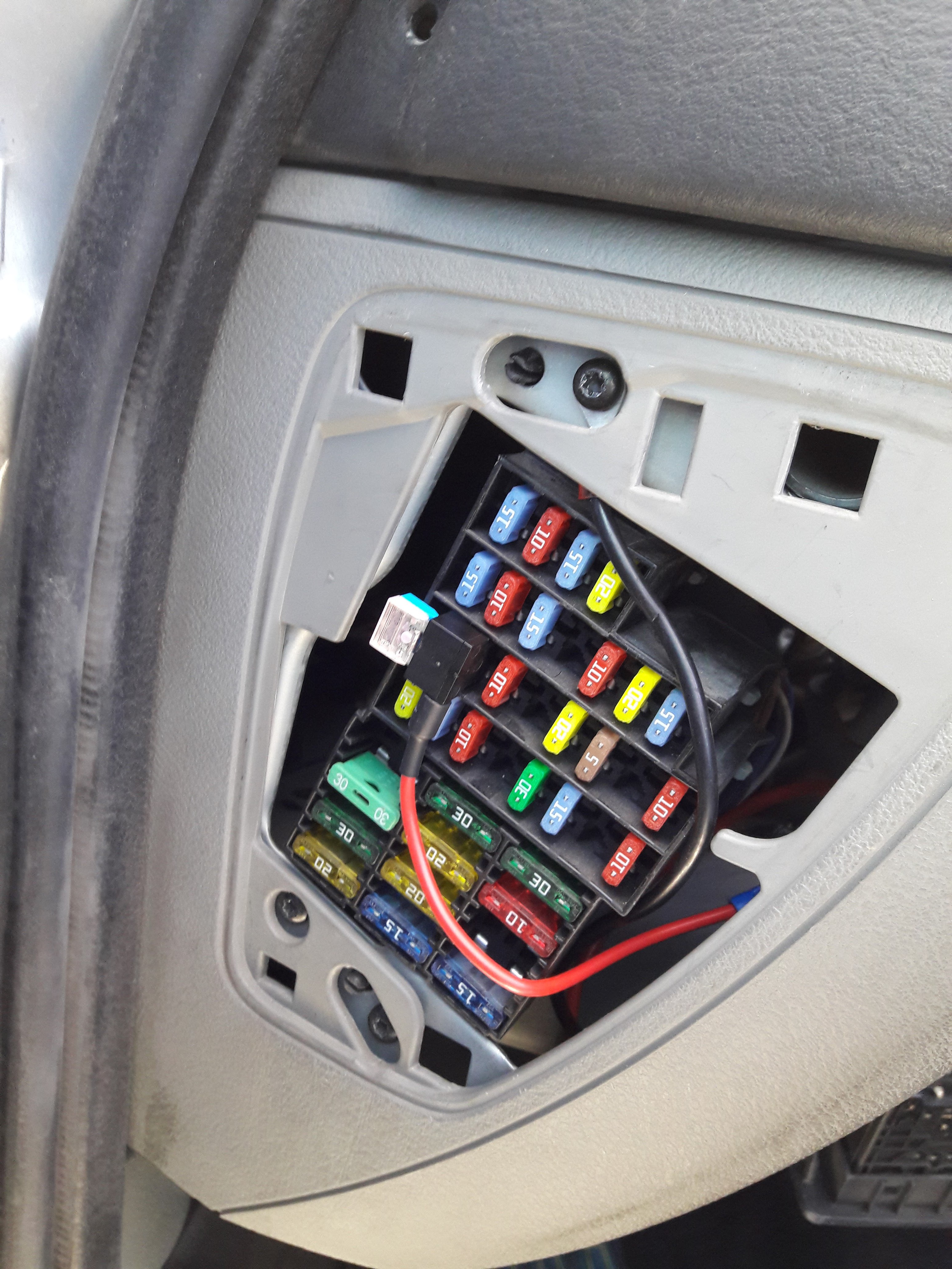
11/07/2017 at 12:22 • 0 commentsI installed my new pcb for the smartphone remote control in my car:
I added a 12V circuit from the car radio fuse:
![]()
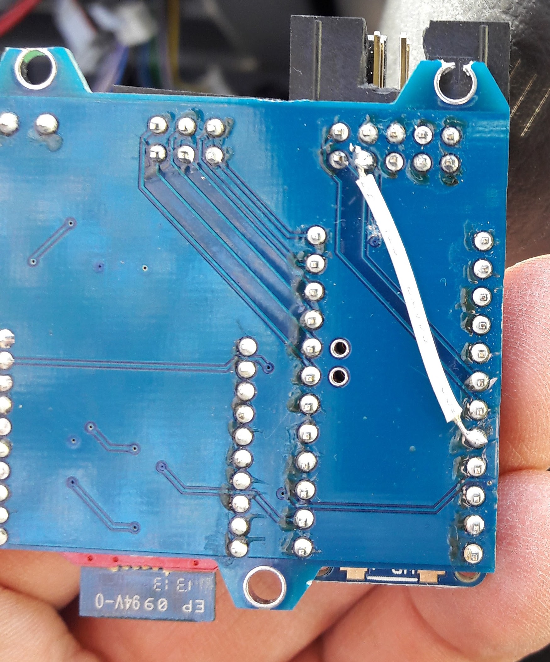
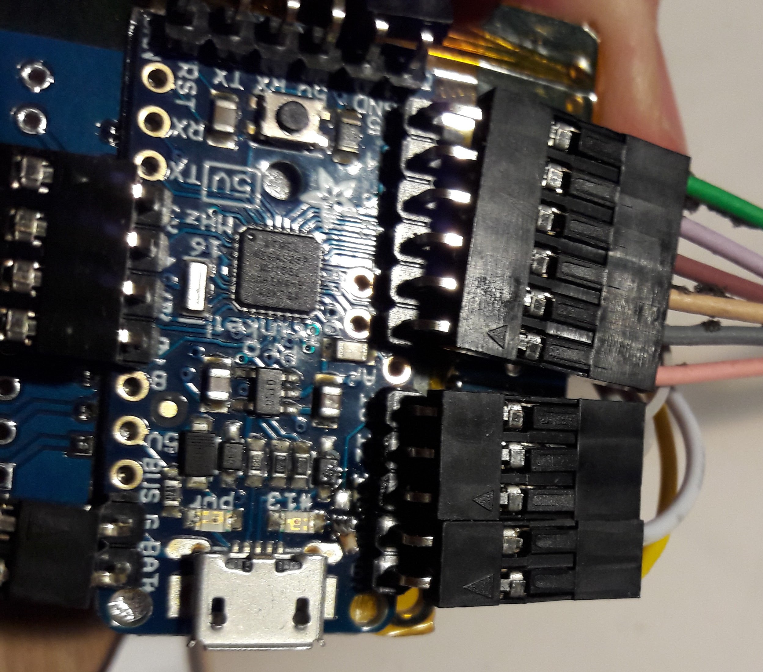
... bodged the D13 pin to D8 pin (the led on the trinket board might prevent the digital input from working properly)
![]()
and installed it in a small compartment near the fuse box:
![]()
(everything in wrapped with heat shrink tubing)
I had to modify the 10 pin header to insert the cable with a 180 degrees rotation and a small commit to github did the rest.
Everything is working so far and I added a task on Tasker to start the webradio app when it detect the bluetooth connection to the hid bluetooth remote control.
-
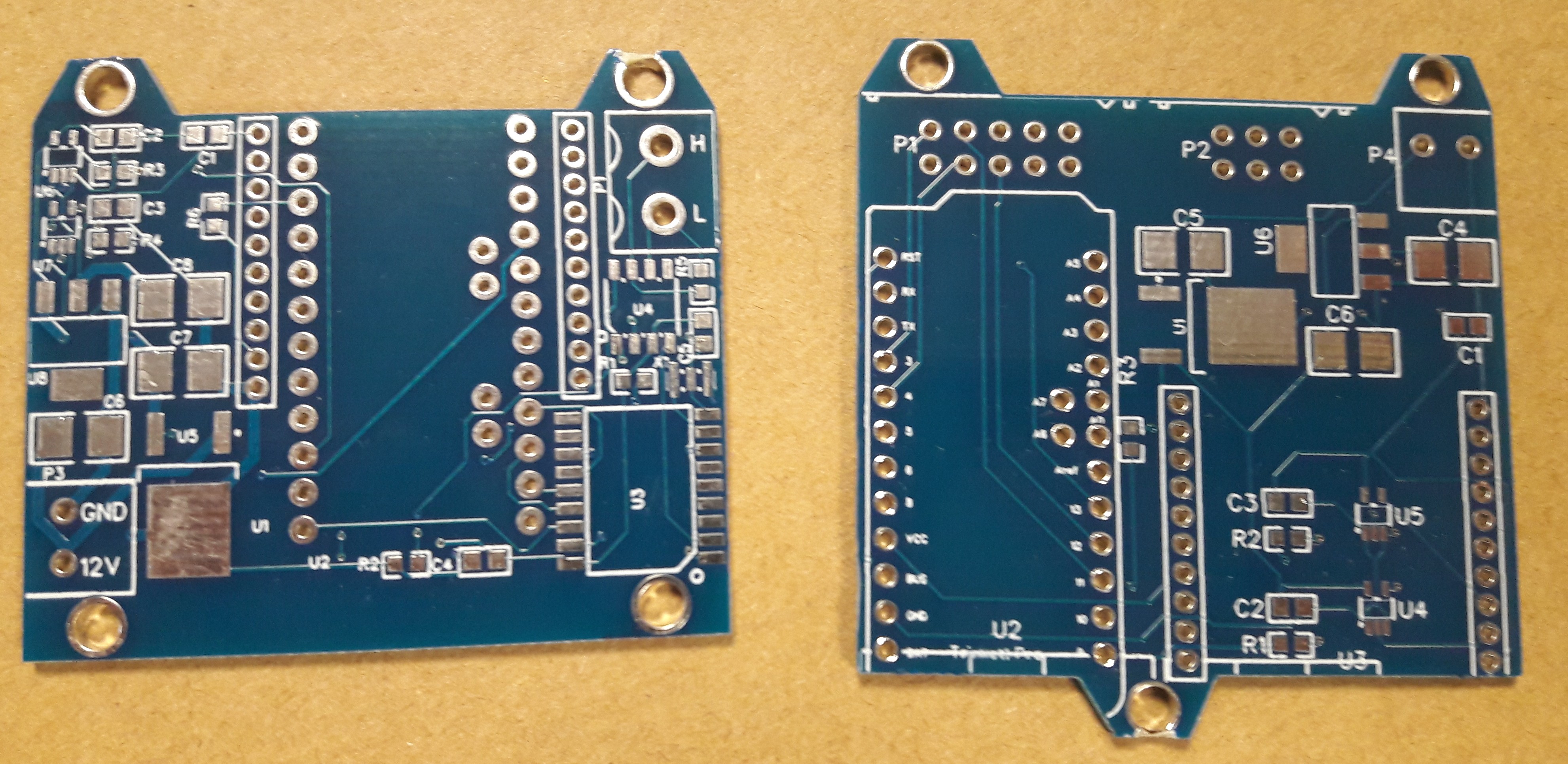
Got my pcb's
11/06/2017 at 08:24 • 0 comments![]()
-
Fails with 3.3V and 8MHz (and bonus)
10/18/2017 at 21:54 • 0 commentsBefore I decided to make pcb's for my canbus and remote control boards, I wanted to use a 3.3V CAN SPI Mikroelktronika's Click board.
The Click board needs to be modified to 16MHz for the MCP2515 Can interface to be compatible with the Arduino library. No big deal.
To make the project smaller, I'd go to the Arduino Fio boards as I'm using bluetooth modules in a Xbee from factor:![]()
At first glance, it has only pros:
- small form factor (compared to a stack of Arduino Uno + shield(s))
- Xbee header
- 3.3V like the bluetooth module and the CAN SPI Mikroelktronika's Click board...
The last thing bited me: at 3.3V Arduino board usually have a 8MHz oscillator. It seems that the canbus library for Arduino doesn't like to work at 8MHz. I'm not sure of that, if you know where I failed, please contact me...
I then tried to use a overclocked 3.3V 16MHz Arduino board by replacing the Arduino 8MHz resonator with a 16MHz one. I doesn't work neither as the bootloader is now at 115200 bauds instead 57600. I gave up at this stage and decided to make my own pcb to achievemy small form factor goal.
Bonus fail:
Murphy's law: when you do wiring, the only screw you have is inserted between your wire and the spacer:
![]()
use double sided tape!
-
2$ pcbs and gerber merging
10/18/2017 at 21:29 • 0 commentsI'm evaluating the jlcpcb.com service. It's basically free : 2$ for 5 pcbs (100x100mm max). As I have 2 boards, the first one should be 2$ (for 5 pieces), but the 2nd one is 5$ (for 5 pieces). It isn't that much but the 2 boards combined are less than the 100x100mm authorized surface. I also wanted to try the GerberPanelizer.exe software discussed on the hackaday blog: https://hackaday.com/2017/06/21/panelizing-boards-the-easy-way/)
So I took the gerbers from EasyEDA from the can and the remote boards and merged them on a single 100x100mm pcb. Here is the resulting image with 2 canbus and 2 remote control boards panelized:
![]()
Here are 10 canbus and 10 remote control pcbs for 2$...
-
PCB for the bluetooth HID remote control
10/18/2017 at 21:00 • 0 commentsI'm not a huge fan of the 0.1" dupont headers as they are not super reliable (no retaining clip, no keying for idiot proofing...):
![]()
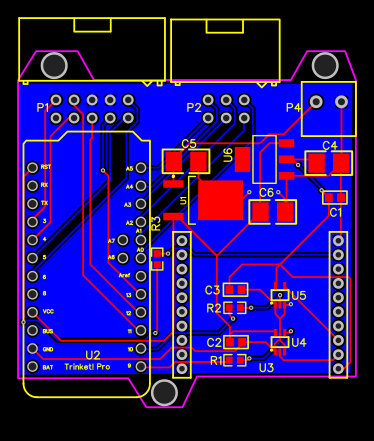
So, I made a PCB with IDC headers (10-pin header for the D-pad with clickable rotary encoder; 6-pin header for the Renault 3x3 matrix remote control).
Here is the link to the EasyEDA project (where you can download gerber files and BOM):
https://easyeda.com/moimeme4/mergeBT-4f19506c93c54159ba06ac12d7cdefa4
![]()
![]()
-
PCB for Canbus and bluetooth SPP
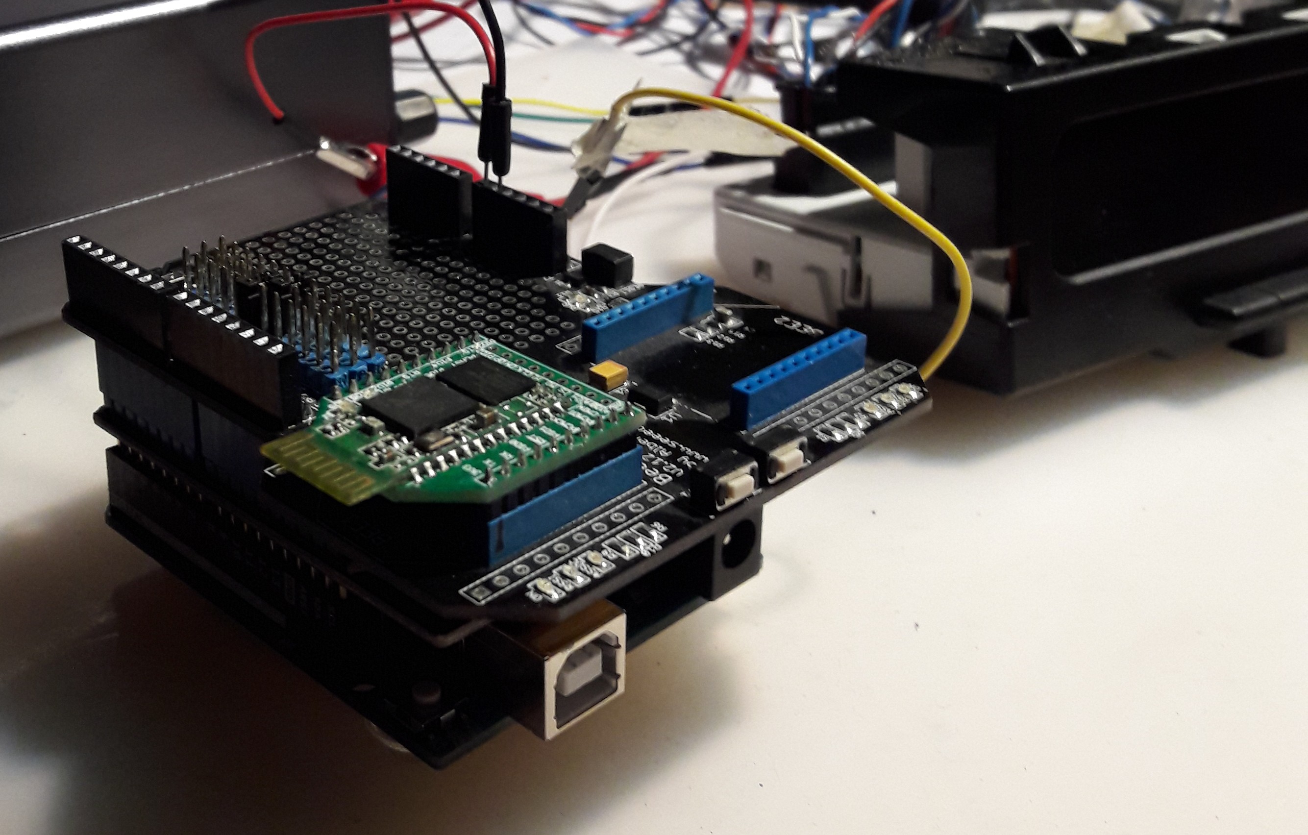
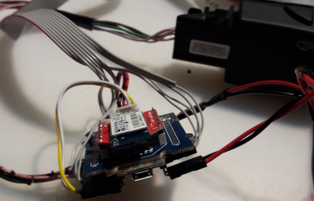
10/18/2017 at 20:49 • 0 commentsi have a working prototype that displays everything I want from the bluetooth link of my smartphone to the canbus of the Renault "Update List screen". But as it is, it needs:
- 1 Arduino Uno board
- 1 Canbus shield (Seeedstudio)
- 1 bee shield + BT module in Xbee form factor
The stack is pretty bulky.
![]()
So I decided to integrate all of this on a pcb (except the Arduino board: I will use a Pro mini as a module to solder on the pcb).
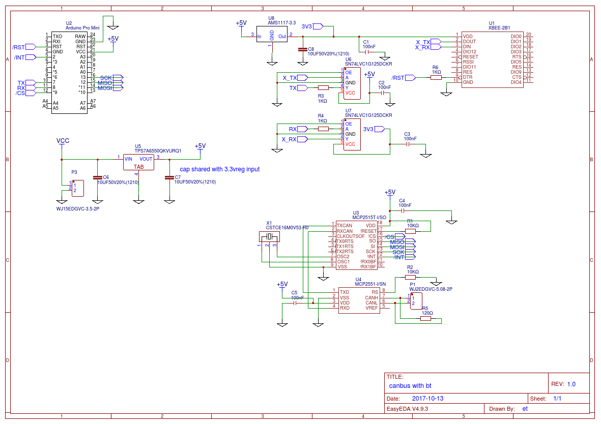
It is an excuse to try the EasyEDA online editor. The "user experience" is pretty good except I don't like the fact that you need to be connected to use it. Here is the link to the project:
https://easyeda.com/moimeme4/can-1577f49e7cb848ee872ee9e1ce39179f
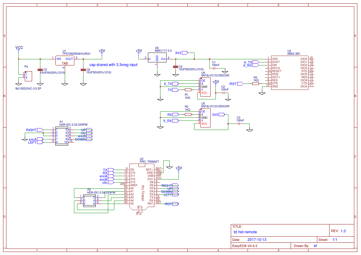
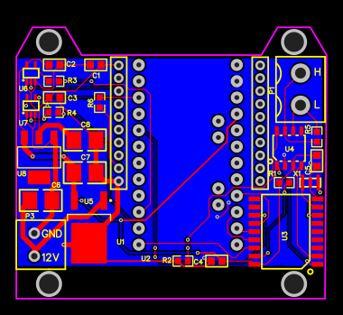
and a screenshot of the schematic and the pcb:(if you want to reproduce it, you can download gerbers and BOM from the link of the project).
![]()
![]()
I'm using a automotive 5V regulator TPS7A6550 to prevent nasty spikes from the 12V accessory rail.
The pcb's are ordered, I'm waiting for them to check if there is no mistake...
-
Car wiring
10/18/2017 at 15:34 • 0 commentsI have 2 Arduino boards to fit in my car:
- one is driving the CANbus display => it will be fitted in the glove box for ease of debugging
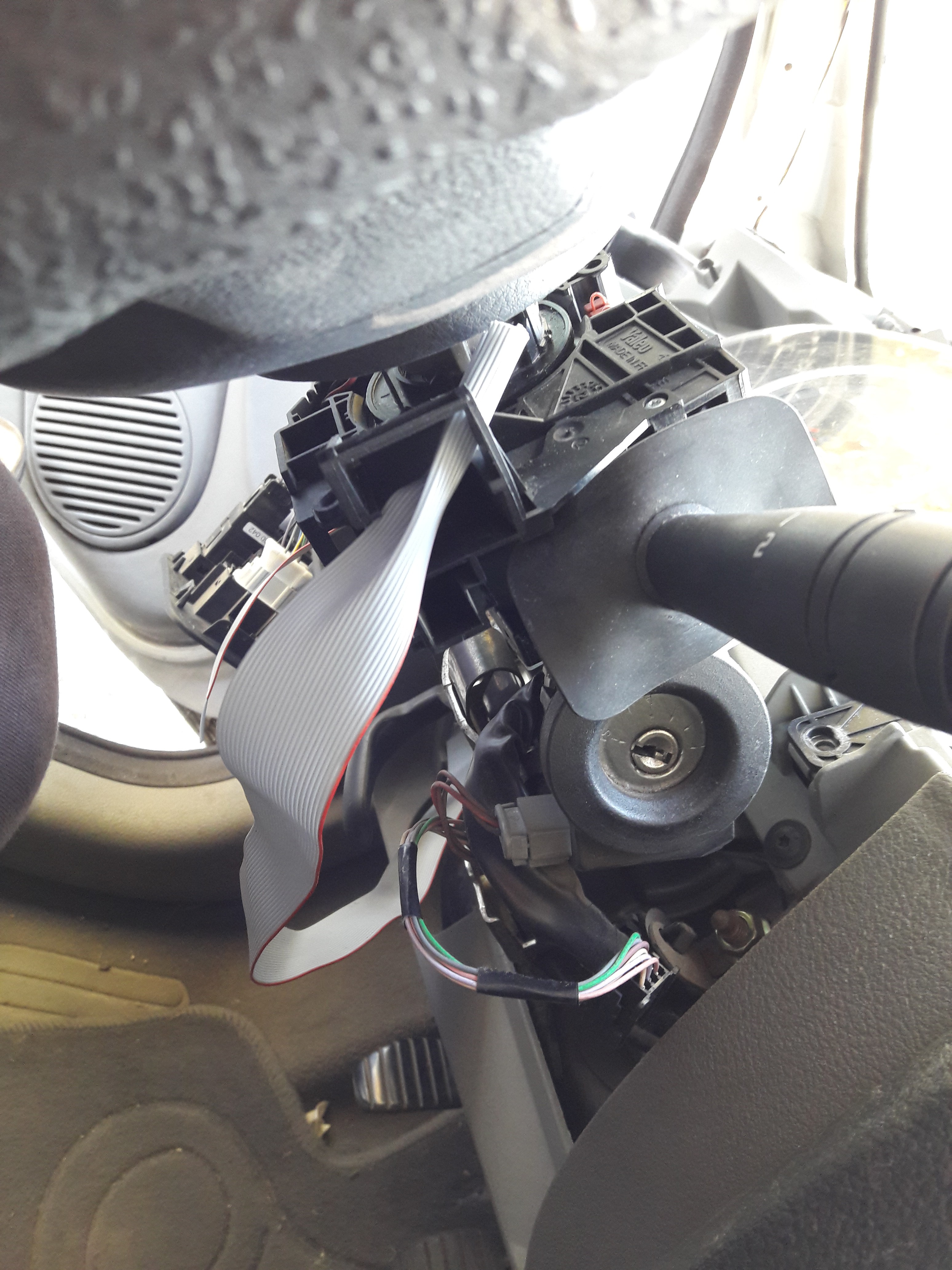
- the second one is the bluetooth remote control for the smartphone => it will be fitted near the stearing wheel (where the remote control buttons are attached)
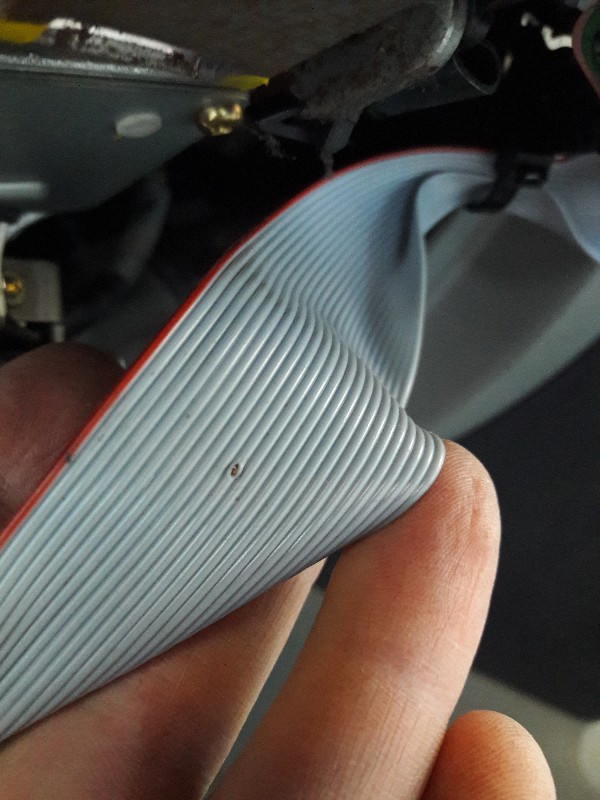
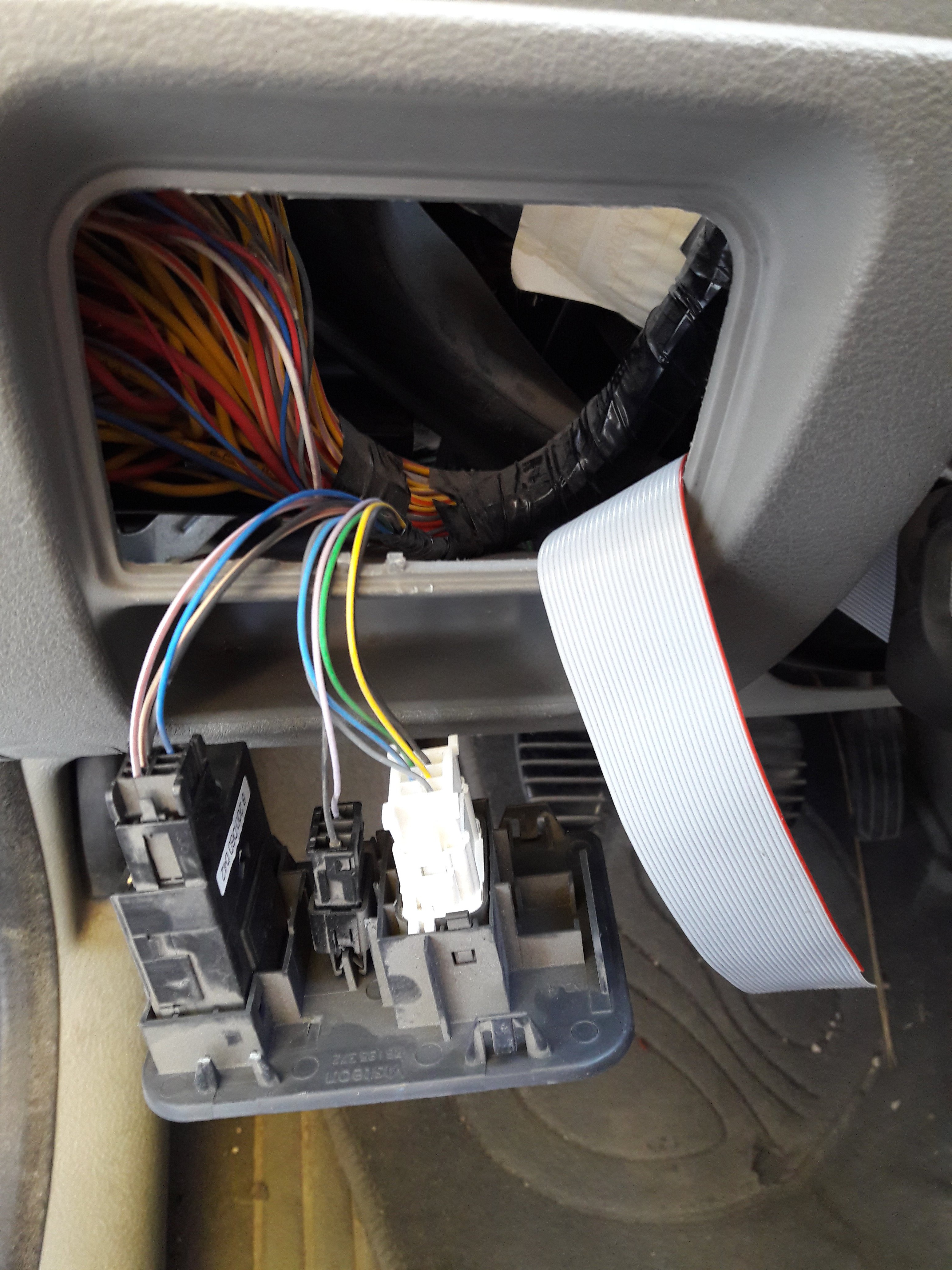
The easiest is the remote control: a ribbon cable is running between the remote control attached to the steering and a compartment near the fuse box:
![]()
![]()
The arduino board will sit here waiting for a firmware update.
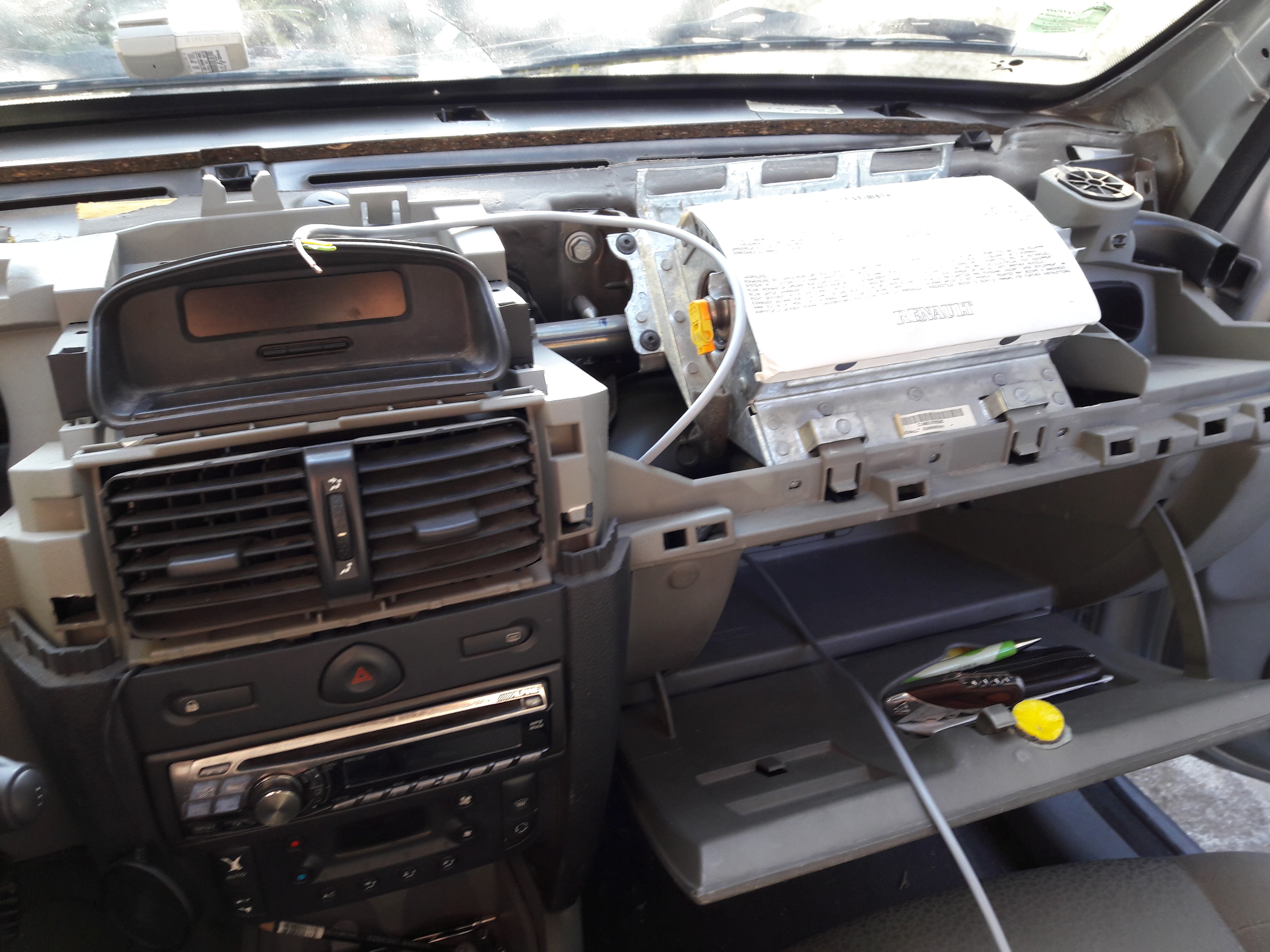
For the display, it is trickier as I have to remove the dashboard bezel. I runned a 4-wire cable (+12V acc, GND, CANH, CANl) between the display and the glove box:
![]()
The arduino board with the canbus interface and the bluetooth spp module will be in a case in the glove box.
It's time to find some box for my boards...
-
BT remote shrinkification
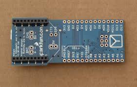
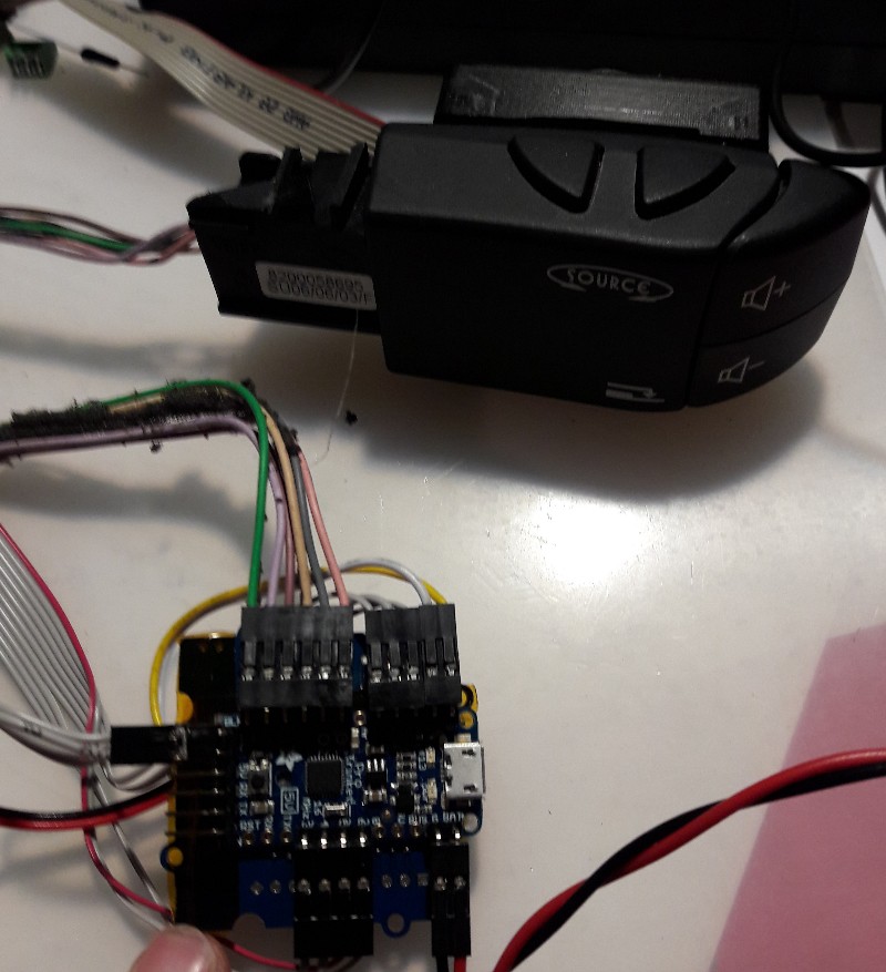
10/18/2017 at 15:22 • 0 commentsI've modified the bluetooth remote control of the smartphone to be smaller. I did that with :
- an Adafruit Pro Trinket board
- a Xbee socket for the RN42 BT HID module
![]()
![]()
I intend to fit this module wrapped in shrink tube inside a compartment of the car. It is near the fuse box and I can open it by just removing a bezel (no screws!) : it is pretty mandatory for the future updates of the firmware.
-
Retrieving infos from smartphone bluetooth
10/09/2017 at 21:51 • 0 commentsNow I have a working canbus display, but how to get song titles from my smartphone and send it to the display:
- every time a new song is played, a notification flashes on the smartphone's screen: I will use an app called AutoNotification (plugin of the popular Tasker app https://joaoapps.com/autonotification/) to extract the song title and the artist name
- I will modify a Tasker plugin to send the text to a bluetooth SPP receiver connect to the Arduino board that drives the canbus display: https://ilias.giechaskiel.com/posts/bluetooth_serial/index.html https://github.com/giech/arduinotaskerbluetooth
- I will create a Tasker profile to check if a new notification is there and the send via Bluetooth to the canbus display thank to the bt plugin
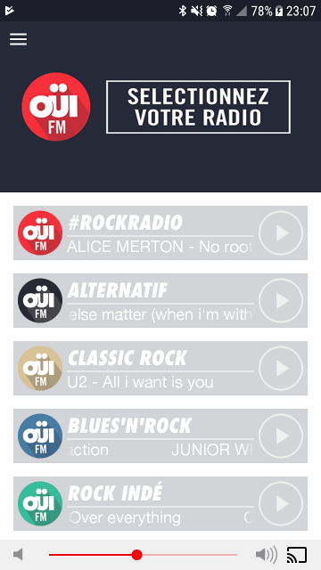
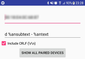
Here is a screenshot of the webradio (ouifm, but it should work with any music player that send notifications) app that I like to listen to:
![]()
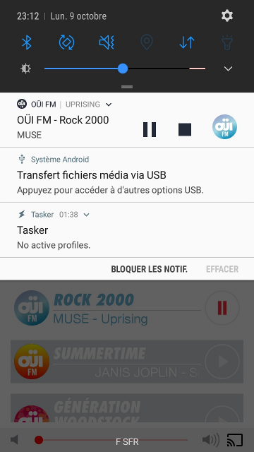
And a notification of the current song:![]()
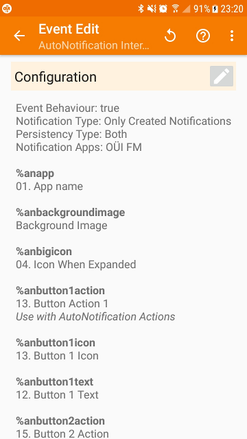
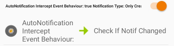
The config for the autonotification interception in Tasker:
![]()
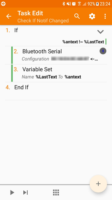
The corresponding task that fires a bluetooth message at every new notification:
![]()
The bluetooth serial plugin config (after this discussion: https://github.com/giech/arduinotaskerbluetooth/issues/2, the plugin is modified to my purpose and is available on google play https://play.google.com/store/apps/details?id=com.giechaskiel.ilias.bluetoothserialfromtasker, than you Ilias!):
![]()
(The MAC address of the bt moule is blurred, I don't know if it really matters...)
And finally, the Tasker profile on top of that:
![]()
My first intention was to plug the SPP BT module on the hardware UART of the Arduino board to use indiffrently the USB or the BT link without code changes. But, as I still have some issues (some notifications are lost, ...), I finally plugged the SPP BT module as a software serial interface and I use the USB link to debug my program.
The corresponding Github commit: b287b22
I don't know yet why I'm dropping some notifications... I'm suspecting:
- the notifications interception plugin: I may have configurate it poorly
- the bluetooth module: there is so little data on this that I don't know if I'm using it properly: I will probably switch to another RN-42 (like on the bluetooth remote control) but as a SPP link this time
- the software serial code: the NeoSWserial library gives a handler that I might call too slowly
If anyone had dropping characters on this kind of SPP module, please let me know how do you solved that issue.
-
Reverse engineering the Renault Update List display - Part 3
09/28/2017 at 11:33 • 3 commentsAt this time, I can send text to my display on the canbus but I need the Renault car radio attached to the display to make it function properly. My goal is to throw away this head unit and use my Alpine one. I logged some canbus packets and I discovered a few things:
- The 0x121 ID is acknowledged by the display with a 0x521 ID packet
![]()
- There is a keep alive dialog between the head unit and the display: Can ID's 0x3CF and 0x3DF are send on a regular basis to check if the other one is attached on the canbus.
![]()
![]()
For the other Can ID's, I was stucked. At this moment, I was fortunate enough to find a guy who did the same thing with the opposite goal: he wanted his custom display to work as the Renault one. His work is based on a very similar Megane AFFA3 display.
I didn't understand everything despite the google trad, but most of the infos I was missing was here:
https://translate.googleusercontent.com/translate_c?anno=2&depth=1&hl=fr&rurl=translate.google.com&sl=pl&sp=nmt4&tl=en&u=http://megane.com.pl/topic/47797-wyswietlacz-radia-update-list-protokol/page__hl__wy%25C5%259Bwietlacz%2520radia%2520update%2520list&usg=ALkJrhgGbHh_iqpb54xLhMpq9wUkCJVQuA
Here is a log:
FRAME 3cf :ID=975: LEN=8:69:01:A2:A2:A2:A2:A2:A2
FRAME 3cf :ID=975: LEN=8:61:11:00:A2:A2:A2:A2:A2
FRAME 3cf :ID=975: LEN=8:61:11:00:A2:A2:A2:A2:A2
FRAME 3df :ID=991: LEN=8:7A:01:81:81:81:81:81:81 // start sync
FRAME 3df :ID=991: LEN=8:79:00:81:81:81:81:81:81 // sync ok
FRAME 3cf :ID=975: LEN=8:61:11:00:A2:A2:A2:A2:A2
FRAME 3df :ID=991: LEN=8:7A:01:81:81:81:81:81:81
FRAME 3df :ID=991: LEN=8:70:1A:11:00:00:00:00:01 // sync display
FRAME 1c1 :ID=449: LEN=8:70:A2:A2:A2:A2:A2:A2:A2
FRAME 4a9 :ID=1193:LEN=8:74:81:81:81:81:81:81:81 // response to a9
FRAME 5c1 :ID=1473:LEN=8:74:81:81:81:81:81:81:81 // response to 1c1
FRAME 3df :ID=991: LEN=8:70:1A:11:00:00:00:00:01
FRAME 3df :ID=991: LEN=8:70:1A:11:00:00:00:00:01
FRAME 121 :ID=289: LEN=8:70:81:81:81:81:81:81:81 // init display
FRAME 1b1 :ID=433: LEN=8:70:81:81:81:81:81:81:81 // register display
FRAME 5b1 :ID=1457:LEN=8:74:A2:A2:A2:A2:A2:A2:A2 // response to 1c1
FRAME 521 :ID=1313:LEN=8:74:A2:A2:A2:A2:A2:A2:A2
FRAME 3cf :ID=975: LEN=8:69:00:A2:A2:A2:A2:A2:A2
FRAME 1b1 :ID=433: LEN=8:04:52:02:FF:FF:81:81:81 // enable display
FRAME 5b1 :ID=1457:LEN=8:74:A2:A2:A2:A2:A2:A2:A2
FRAME 1c1 :ID=449: LEN=8:02:64:0F:A2:A2:A2:A2:A2
FRAME 121 :ID=289: LEN=8:10:1C:7F:55:55:3F:60:01
FRAME 121 :ID=289: LEN=8:21:46:4D:20:20:20:20:20
FRAME 121 :ID=289: LEN=8:22:20:10:52:41:44:49:4F
FRAME 521 :ID=1313:LEN=8:30:01:00:A2:A2:A2:A2:A2
FRAME 521 :ID=1313:LEN=8:74:A2:A2:A2:A2:A2:A2:A2
FRAME 5c1 :ID=1473:LEN=8:74:81:81:81:81:81:81:81 // response to 1c1
FRAME 3df :ID=991: LEN=8:79:00:81:81:81:81:81:81 // ping
FRAME 3cf :ID=975: LEN=8:69:00:A2:A2:A2:A2:A2:A2 // pong
FRAME 3df :ID=991: LEN=8:79:00:81:81:81:81:81:81 //...
FRAME 3cf :ID=975: LEN=8:69:00:A2:A2:A2:A2:A2:A2
FRAME 121 :ID=289: LEN=8:10:1C:77:65:55:1F:71:01
FRAME 521 :ID=1313:LEN=8:30:01:00:A2:A2:A2:A2:A2
FRAME 521 :ID=1313:LEN=8:30:01:00:A2:A2:A2:A2:A2
FRAME 121 :ID=289: LEN=8:22:32:10:20:45:55:52:4F
FRAME 121 :ID=289: LEN=8:24:00:81:81:81:81:81:81
FRAME 521 :ID=1313:LEN=8:74:A2:A2:A2:A2:A2:A2:A2
FRAME 121 :ID=289: LEN=8:21:45:55:52:4F:50:45:20
FRAME 3df :ID=991: LEN=8:79:00:81:81:81:81:81:81
FRAME 3cf :ID=975: LEN=8:69:00:A2:A2:A2:A2:A2:A2
FRAME 3df :ID=991: LEN=8:79:00:81:81:81:81:81:81
FRAME 3cf :ID=975: LEN=8:69:00:A2:A2:A2:A2:A2:A2
FRAME 3df :ID=991: LEN=8:79:00:81:81:81:81:81:81
FRAME 3cf :ID=975: LEN=8:69:00:A2:A2:A2:A2:A2:A2
FRAME 3df :ID=991: LEN=8:79:00:81:81:81:81:81:81
FRAME 3cf :ID=975: LEN=8:69:00:A2:A2:A2:A2:A2:A2
FRAME 3df :ID=991: LEN=8:79:00:81:81:81:81:81:81
FRAME 3cf :ID=975: LEN=8:69:00:A2:A2:A2:A2:A2:A2
FRAME 3df :ID=991: LEN=8:79:00:81:81:81:81:81:81
...
This init sequence is in the Arduino code https://github.com/manu-t/autoradio-interface/blob/master/UpdateListDisplay/UpdateListDisplay.ino
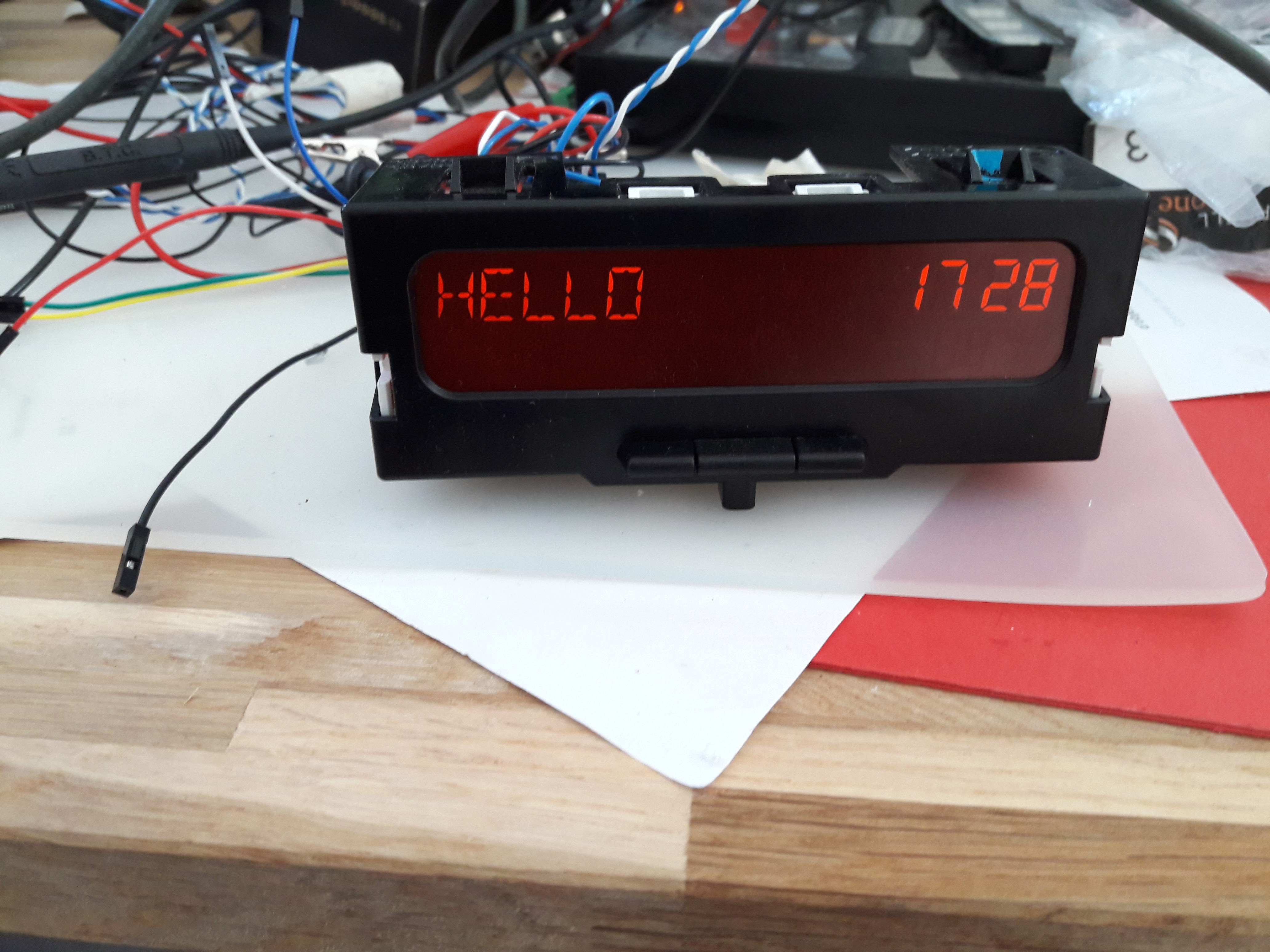
With some tries and errors, I finally ended to send text to the display without the Renault car radio attached!
![]()
Smart car radio
I reversed engineered the canbus screen in my Clio and created a bluetooth remote control to listen to webradios without touching my phone.