0%
0%
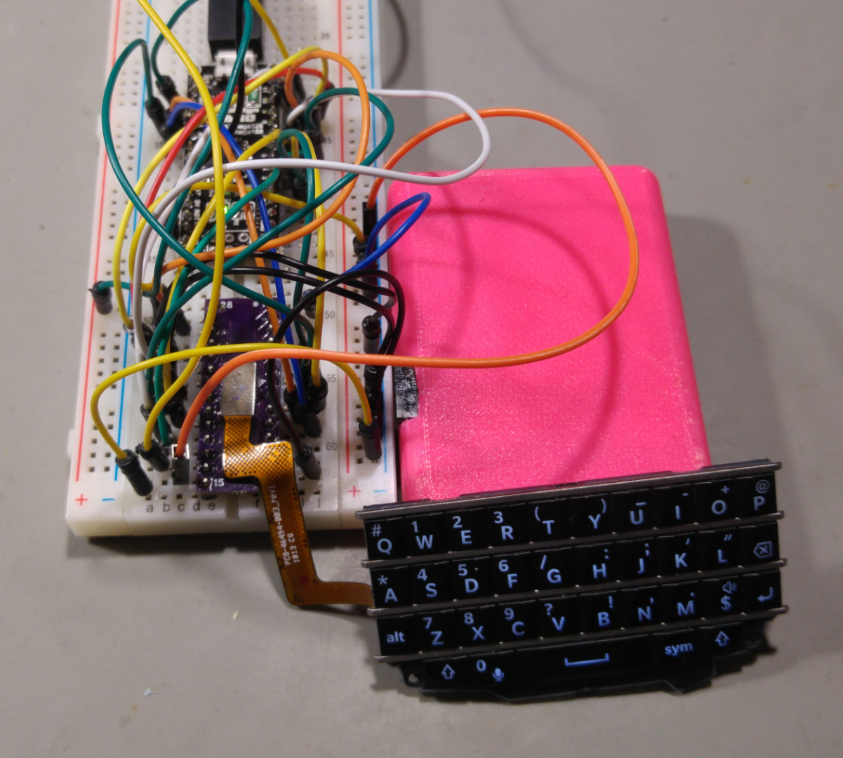
PIMP (Personal Information Manager & Pager)
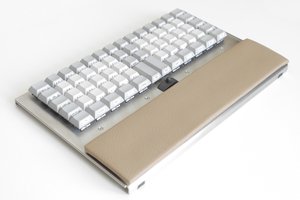
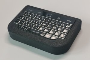
A small MCU based PIM with Pager functionallity
 WooDWorkeR
Become a Hackaday.io member
Already have an account? Log in.
Just one more thing
To make the experience fit your profile, pick a username and tell us what interests you.
Pick an awesome username
hackaday.io/
Your profile's URL: hackaday.io/username. Max 25 alphanumeric characters.
Pick a few interests
Projects that share your interests
People that share your interests


 Jesse Robinson (beacon)
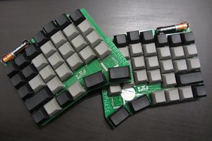
 ZitaoTech
Oh, I see. We all at hackaday trying to do the same thing - DIY palmtop with custom firmware. The problem is that many applications on your PIMP will not run on my Coolsystem without modification. I am going to collect information about every such device and maybe (just maybe) write some code to make portable applications run on different devices.