WooDWorkeR
-
First steps for the Keyboard controller
03/25/2018 at 21:56 • 0 comments![]()
A very important part of the PIMP project is the Keyboard. Without a keyboard, no notetaking capabilities.
The Blackberry Q10 keyboard has a basic keyboard matrix and needs 5 pins for the rows and 7 pins for columns.
The first iteration of this controller is build with an Arduino Nano. Later I may change to a cheaper Microcontroller like STM8, EFM8 or a SAMD10.
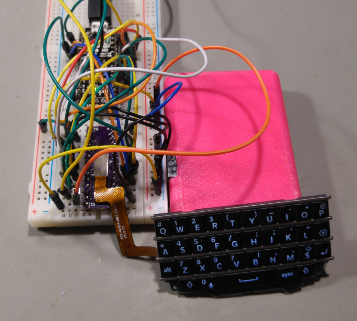
The Prototype
The firmware is pretty easy. Scanning the keyboard matrix, checking for button changes and then writing the pressed keys to the serial console. Of cause, there is a little bit "magic" in between to check if keypresses are actually printable characters. And because we can we also care for the keyboard backlight.
---------- more ----------The Source
byte rows[] = {2,3,4,5,6,7,8}; const int rowCount = sizeof(rows)/sizeof(rows[0]); byte cols[] = {A0, A1, A2, 12, 11}; const int colCount = sizeof(cols)/sizeof(cols[0]); bool keys[colCount][rowCount]; bool lastValue[colCount][rowCount]; bool changedValue[colCount][rowCount]; char keyboard[colCount][rowCount]; char keyboard_symbol[colCount][rowCount]; int keyboardLightSteps = 20; int keyboardLight = 20; bool symbolSelected; void setup() { keyboard[0][0] = 'q'; keyboard[0][1] = 'w'; keyboard[0][2] = NULL; // symbol keyboard[0][3] = 'a'; keyboard[0][4] = NULL; // ALT keyboard[0][5] = ' '; keyboard[0][6] = NULL; // Mic keyboard[1][0] = 'e'; keyboard[1][1] = 's'; keyboard[1][2] = 'd'; keyboard[1][3] = 'p'; keyboard[1][4] = 'x'; keyboard[1][5] = 'z'; keyboard[1][6] = NULL; // Left Shift keyboard[2][0] = 'r'; keyboard[2][1] = 'g'; keyboard[2][2] = 't'; keyboard[2][3] = NULL; // Right Shit keyboard[2][4] = 'v'; keyboard[2][5] = 'c'; keyboard[2][6] = 'f'; keyboard[3][0] = 'u'; keyboard[3][1] = 'h'; keyboard[3][2] = 'y'; keyboard[3][3] = NULL; // Enter keyboard[3][4] = 'b'; keyboard[3][5] = 'n'; keyboard[3][6] = 'j'; keyboard[4][0] = 'o'; keyboard[4][1] = 'l'; keyboard[4][2] = 'i'; keyboard[4][3] = NULL; // Backspace keyboard[4][4] = '$'; keyboard[4][5] = 'm'; keyboard[4][6] = 'k'; keyboard_symbol[0][0] = '#'; keyboard_symbol[0][1] = '1'; keyboard_symbol[0][2] = NULL; keyboard_symbol[0][3] = '*'; keyboard_symbol[0][4] = NULL; keyboard_symbol[0][5] = NULL; keyboard_symbol[0][6] = '0'; keyboard_symbol[1][0] = '2'; keyboard_symbol[1][1] = '4'; keyboard_symbol[1][2] = '5'; keyboard_symbol[1][3] = '@'; keyboard_symbol[1][4] = '8'; keyboard_symbol[1][5] = '7'; keyboard_symbol[1][6] = NULL; keyboard_symbol[2][0] = '3'; keyboard_symbol[2][1] = '/'; keyboard_symbol[2][2] = '('; keyboard_symbol[2][3] = NULL; keyboard_symbol[2][4] = '?'; keyboard_symbol[2][5] = '9'; keyboard_symbol[2][6] = '6'; keyboard_symbol[3][0] = '_'; keyboard_symbol[3][1] = ':'; keyboard_symbol[3][2] = ')'; keyboard_symbol[3][3] = NULL; keyboard_symbol[3][4] = '!'; keyboard_symbol[3][5] = ','; keyboard_symbol[3][6] = ';'; keyboard_symbol[4][0] = '+'; keyboard_symbol[4][1] = '"'; keyboard_symbol[4][2] = '-'; keyboard_symbol[4][3] = NULL; keyboard_symbol[4][4] = NULL; keyboard_symbol[4][5] = '.'; keyboard_symbol[4][6] = '\''; Serial.begin(115200); for(int x=0; x<rowCount; x++) { Serial.print(rows[x]); Serial.println(" as input"); pinMode(rows[x], INPUT); } for (int x=0; x<colCount; x++) { Serial.print(cols[x]); Serial.println(" as input-pullup"); pinMode(cols[x], INPUT_PULLUP); } // set pins for the keyboard backlight pinMode(10, OUTPUT); pinMode(9, OUTPUT); setKeyboardBacklight(keyboardLight); symbolSelected = false; } void readMatrix() { int delayTime = 0; // iterate the columns for (int colIndex=0; colIndex < colCount; colIndex++) { // col: set to output to low byte curCol = cols[colIndex]; pinMode(curCol, OUTPUT); digitalWrite(curCol, LOW); // row: interate through the rows for (int rowIndex=0; rowIndex < rowCount; rowIndex++) { byte rowCol = rows[rowIndex]; pinMode(rowCol, INPUT_PULLUP); delay(1); // arduino is not fast enought to switch input/output modes so wait 1 ms bool buttonPressed = (digitalRead(rowCol) == LOW); keys[colIndex][rowIndex] = buttonPressed; if ((lastValue[colIndex][rowIndex] != buttonPressed)) { changedValue[colIndex][rowIndex] = true; } else { changedValue[colIndex][rowIndex] = false; } lastValue[colIndex][rowIndex] = buttonPressed; pinMode(rowCol, INPUT); } // disable the column pinMode(curCol, INPUT); } if (keyPressed(0, 2)) { symbolSelected = true; } } bool keyPressed(int colIndex, int rowIndex) { return changedValue[colIndex][rowIndex] && keys[colIndex][rowIndex] == true; } bool keyActive(int colIndex, int rowIndex) { return keys[colIndex][rowIndex] == true; } bool isPrintableKey(int colIndex, int rowIndex) { return keyboard_symbol[colIndex][rowIndex] != NULL || keyboard[colIndex][rowIndex] != NULL; } void setKeyboardBacklight(int keyboardLight) { analogWrite(10, keyboardLight); analogWrite(9, keyboardLight); } void printMatrix() { for (int rowIndex=0; rowIndex < rowCount; rowIndex++) { for (int colIndex=0; colIndex < colCount; colIndex++) { // we only want to print if the key is pressed and it is a printable character if (keyPressed(colIndex, rowIndex) && isPrintableKey(colIndex, rowIndex)) { String toPrint; if (symbolSelected) { symbolSelected = false; toPrint = String(keyboard_symbol[colIndex][rowIndex]); } else { toPrint = String(keyboard[colIndex][rowIndex]); } // keys 1,6 and 2,3 are Shift keys, so we want to upper case if (keyActive(1,6) || keyActive(2,3)) { toPrint.toUpperCase(); } Serial.print(toPrint); } } } } // a helper method that checks boundaries for the PWM values void changeBackgroundLight(int pwmValue) { if (pwmValue > 255) { pwmValue = 255; } if (pwmValue < 0) { pwmValue = 0; } keyboardLight = pwmValue; setKeyboardBacklight(keyboardLight); } void loop() { readMatrix(); printMatrix(); // key 3,3 is the enter key if (keyPressed(3,3)) { Serial.println(); } // increase backlight if symbol key is pressed if (keyPressed(0,2)) { changeBackgroundLight(keyboardLight + keyboardLightSteps); } // decrease backlight if right shift key is pressed if (keyPressed(2,3)) { changeBackgroundLight(keyboardLight - keyboardLightSteps); } delay(10); } -
Solder once, Beepout Twice
11/16/2017 at 17:07 • 1 commentThought Experiment: You solder a very tiny connector to an breakoutboard to try beep out the thing you connected to that connector. You find a few connections but for Farad sake you can not find others.
You totally must have broken some connections on the disassemly of that board, so you buy a few more components. Would you also check your Connector on that breakout board if that has all the connections you think, beep out all 28 Pins?
I did all this without checking the soldered connector. So i found all the missing connection for the Diodes where on PINs that where not really soldered on the Connector Breakout. I checked then with thin wire direct on the FlexPCB connector and there where all my missing connections.
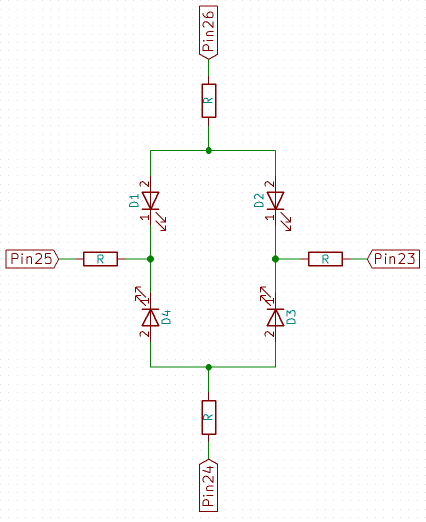
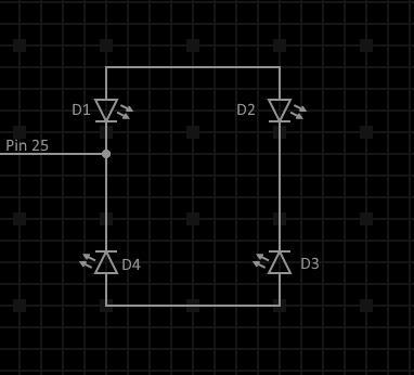
I present you the Blackberry Q10 Keyboard Backlight Pinout :D
![]()
The resistor on this circuit seem to be in the ballpark of 1 Ohm. I tested the LEDs with 3V and they seem to like this voltage, 2.5 is minimum but also very dim
Things i learned:
- Solder once Beepout Twice all your connections, every pin
- Soldering 0.4mm is Hard
-
Blackberry Q10 Keyboard (destructive) Disassembly
10/25/2017 at 22:42 • 6 commentsSo, i found the Q10 Keyboard for my project and JoeN from the EEVBlog Forum also already did the work to reverse engineer the Keyboard matrix.
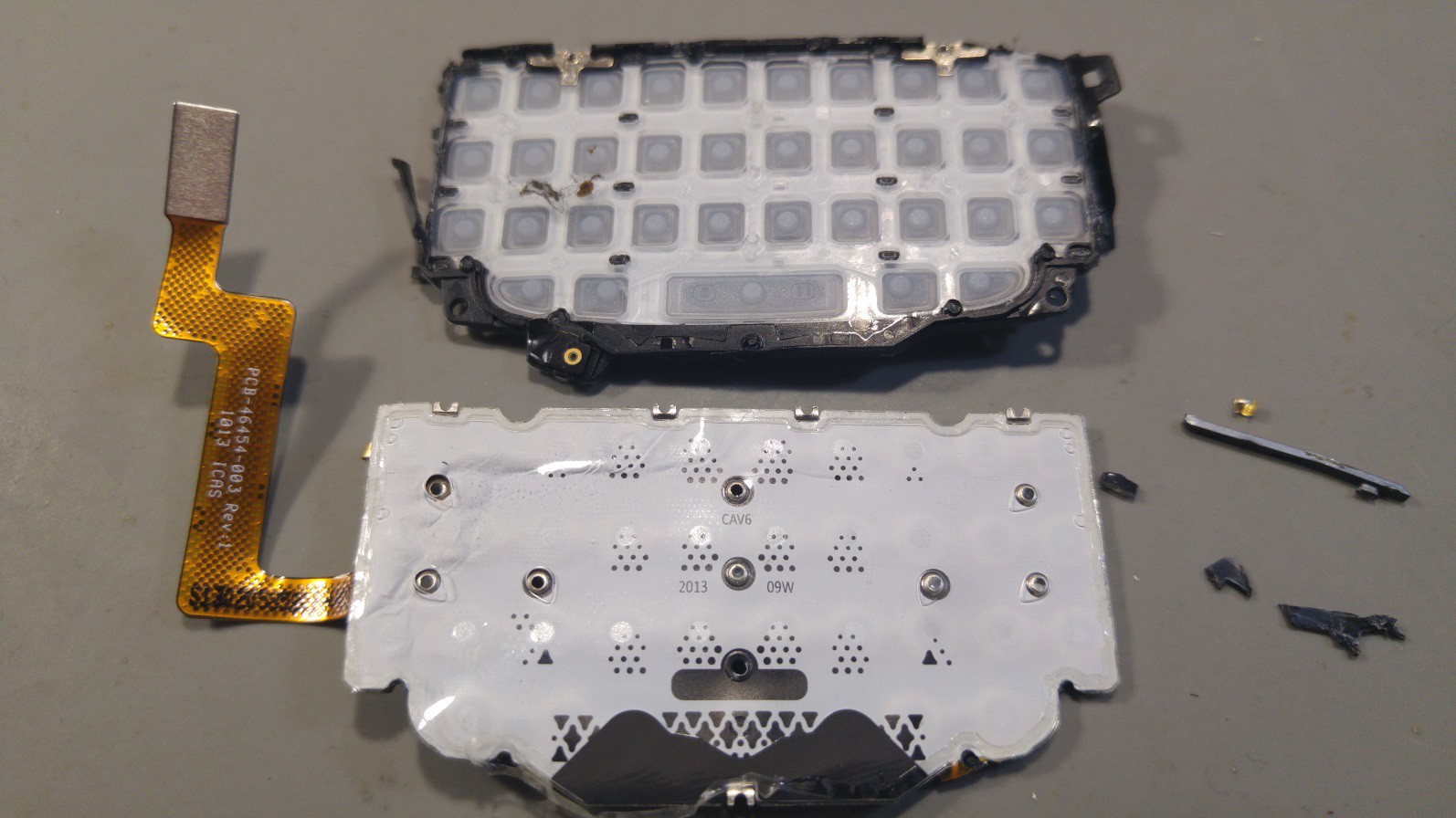
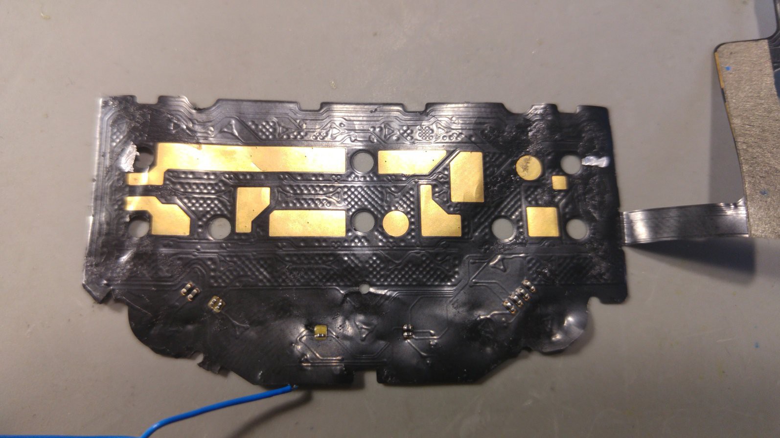
But as i know that this keyboard can also be backlit i wanted to to get the backlight running.At first i tried just the good old try all the pins with all the other pins in Diode testing mode - and i did not really get much out of this. So as Dave Jones always says: “Don't turn it on, take it apart”, i then took it apart.
![]()
![]()
I found a lot of nice metallic tactile domes for the keys, a few Resistors AND 4 LEDs.
Now that i had access to the LEDs i was testing them directly with the diode test mode of my DMM and there they are White LEDs with 2.5v diode drop.
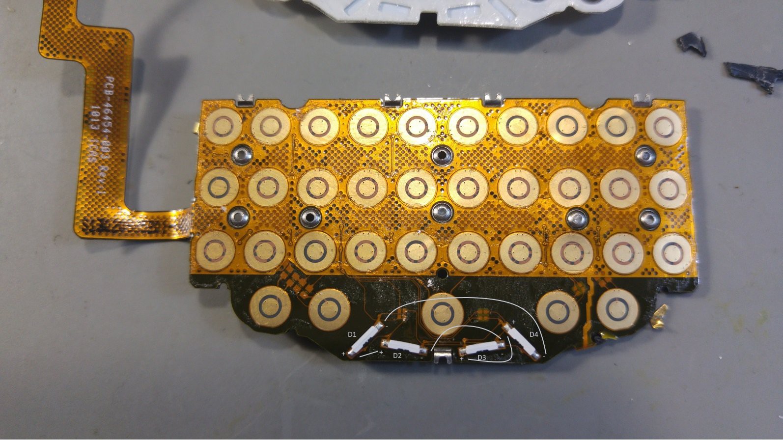
Then i beeped out the connections of the diodes and got a really strange back to back front to front arrangement.![]()
But while removing the flex pcb from the metal back i ripped of one of the resistors, and as i only have one keyboard left, i’ll wait for the next Aliexpress shipment of 6 of them to take another one apart and find the missing connections.
![]()
But i found the grounds and one LED connection for that connector. Hopefully i’ll find them all when i can take another one, more carefully, apart. If anyone has any tips on what this strange LED arrangement is please tell.
JoeN Connector Pinout + my findings
GND 28 1 GND ROW7 27 2 26 3 D1- 25 4 24 5 23 6 ROW1 ROW6 22 7 COL1 ROW5 21 8 ROW2 ROW4 20 9 COL2 COL5 19 10 COL3 ROW3 18 11 GND COL4 17 12 GND 16 13 GND 15 14 -
The maximum Build
10/02/2017 at 13:36 • 5 commentsWhile thinking about this little project there might happend some featurecreep. But i will put all the Ideas for this little Gadget into the wild, so other will maybe give tipps for even more features.
- Hardware
- Output
- Display
- LCD or OLED
- eInk (maybe as backpack for showing pager information)
- LED
- Vibration Motor
- page like functionality
- Display
- Input
- Blackberry Q10 Keyboard
- maybe a stm8 based keyboard controller to not use up all the main MCU pins
- NFC Tag Reader/Write
- Buttons
- Rotary Encoder
- Blackberry Q10 Keyboard
- Other
- Realtime Clock
- Main CPU/MCU
- ESP8266
- not enough pins?
- ESP32
- could be main MCU or also just wifi coprocessor
- STM32
- no build in WiFi
- could try to code in rust-lang
- ESP8266
- Output
- Batteries
- would love to have 2 to 3 days of usage
- Charger via (micro)USB(-C)
- 18650 (Between 1 and 3)
- Storage
- SD/microSD
- create eeprom cartridges?
- need to find a small/cheap pcb edge connector for this
- Connectivity
- WiFi
- ESP8266/ESP32
- LoRa(like)
- 433MHz
- Protocolls
- CoAP?
- IKEA Lamps
- MQTT (read/send)
- CalDAV
- NTP (sync the realtime clock)
- CoAP?
- WiFi
- Apps
- Writing/Notetaking
- Sync via WiFi to Nextcloud?!
- Calendar
- Clock
- Pager
- MQTT based?
- Send in 433MHz spectrum?
- maybe encrypted
- Maybe more via gameboy like cartridges or bin files from sd card
- Writing/Notetaking
- Hardware
-
Q10 Keyboard Adapter (My first hot air experience)
09/29/2017 at 10:12 • 1 commentSolderpaste arrived
Hotair Station arrived
So no i only need to to this, can't be that hard? Am i right? Solderpaste, mhh, i think more is better! (Spoiler: no it's not)
But in the end i got a working a adapter board to develop my Breadboard PIMP :D
PIMP (Personal Information Manager & Pager)
A small MCU based PIM with Pager functionallity