Saabman
-
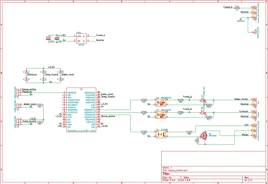
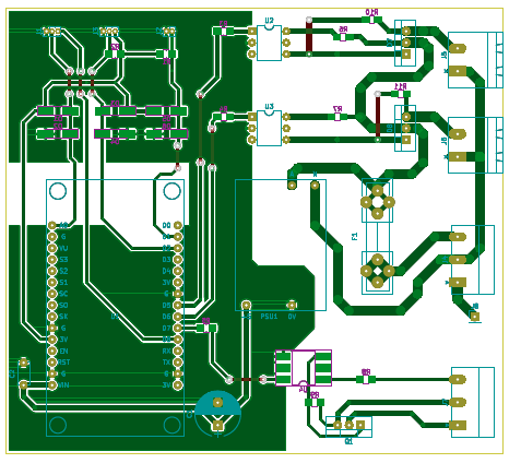
Circuit and PCB Designed
05/19/2018 at 11:32 • 0 commentsKnuckled down this week and got the Circuit drawn up in Kicad and the PCB laid out. reasonably happy with how it came out. Working with Kicad for the first time after using Eagle for the last 10 years or so was a bit of a challenge but with plenty of tutorials and information available anything I struggled with was solved in a minute or 2 with the help of Duck DucK Go.
Next step will be to produce the PCB and put it all together.
![]()
![]()
-
Hardware
03/13/2018 at 10:24 • 0 comments![]()
Things have been moving along a bit slow on this project of late but some progress has been made this week on the circuit design.
Primarily this is a NodeMCU board with a bunch of IO associated with it. Normally I would have just copied and pasted the IO stages of other projects and the job is done but.. I’ve taken the opportunity to jump from using Eagle (which I’ve alsways hated anyway) over to Kicad and I hope I find it more palatable than Eagle. I cut my teeth doing circuit design on Protel 98 I think the version was but with no Mac equivalent about when I made the switch from windows to MacOS (7.6 I think it was) I didn’t have many options.
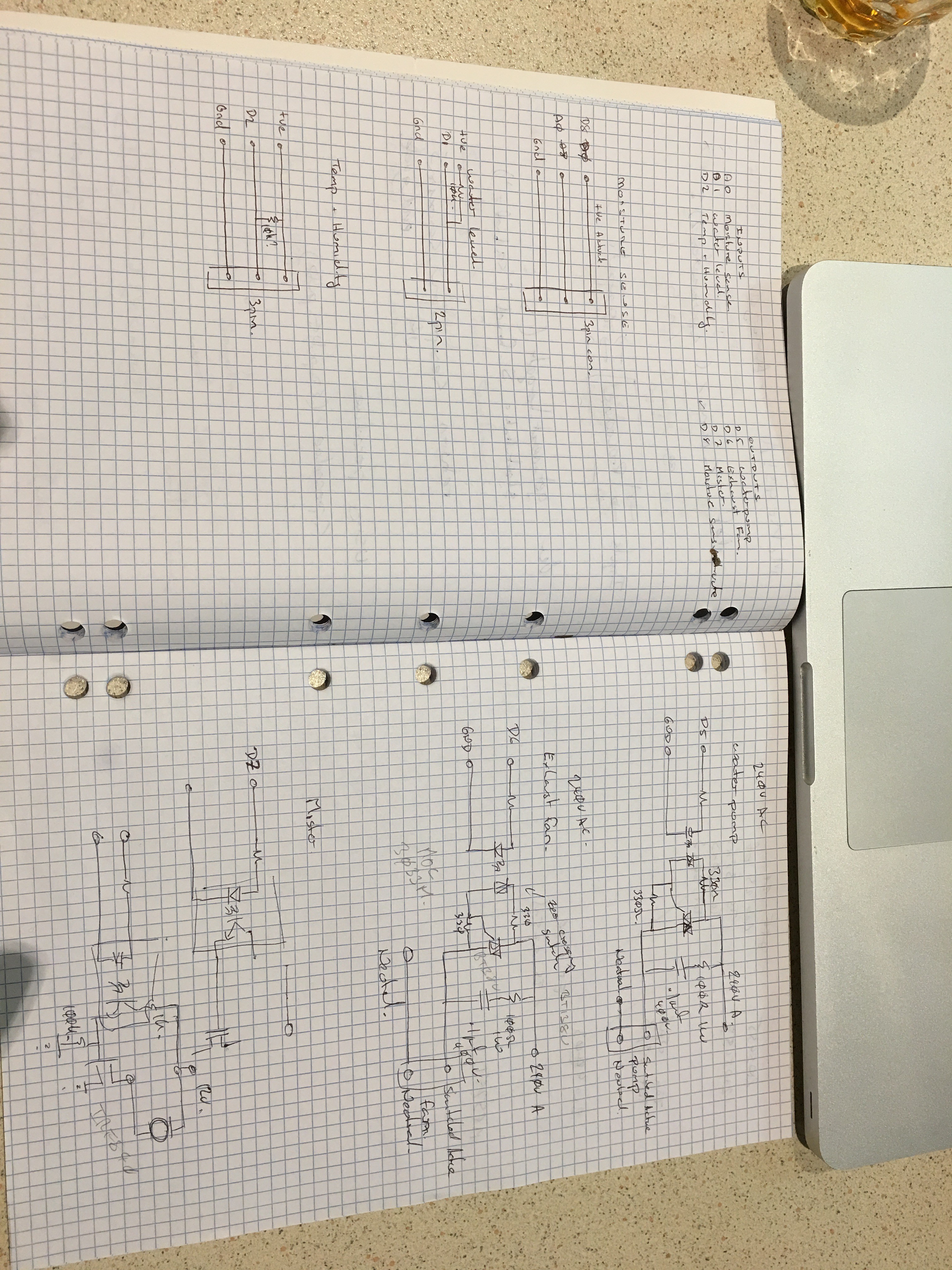
So to get the ball rolling while I come to terms with libraries and the like in Kicad I’ve reverted to sketching the IO stages on paper while I make my component selections than I’ll input it all into Kicad for the schematic capture and board creation.
Inputs are pretty straight forward sensor connects via a connector to the board and wired directly to the NodeMCU. In this case Im expecting the sensors to be fairly close to the board if not directly on it so at this stage I am not considering anything more than clamping diodes to keep induced signals to within the power rails.
Outputs are switching primarily 240V AC devices so opto isolated Triac drivers and Triacs are the order of the day.
At this stage MOC3033 opto isloated zero crossing triac drivers will be used to switch the BT138 600V 12A Triacs - serious over kill for this application but the cost difference for a lower spec triac is pretty negligible and this gives me the advantage of repoursing the circuit for other things :)
The DC switching will also be opto isolated (TLP185) coupled with an IRF840 500V 8A MOSFET as a high side switch. Again a fair bit of over kill but will lend itself to other projects requiring a higher voltage range and more power.
-
Firmware Completion
12/26/2017 at 10:59 • 0 commentsA good run today saw me complete the Firmware, no doubt modifications will be coming but things have progressed enough to move on to the Hardware.
The code is listed below.
from the App it is possible to adjust the setpoints for the Temperature, Humidity and Moisture level pressing the save button stores the values in the EEPROM of the ESP8266 which is read on start up should the 8266 ever be rebooted./************************************************************* Blynk is a platform with iOS and Android apps to control Arduino, Raspberry Pi and the likes over the Internet. You can easily build graphic interfaces for all your projects by simply dragging and dropping widgets. Downloads, docs, tutorials: http://www.blynk.cc Blynk community: http://community.blynk.cc Social networks: http://www.fb.com/blynkapp http://twitter.com/blynk_app Blynk library is licensed under MIT license *************************************************************/ /* Comment this out to disable prints and save space */ #define BLYNK_PRINT Serial #include <SPI.h> #include <ESP8266WiFi.h> #include <BlynkSimpleEsp8266.h> #include <SimpleTimer.h> #include <DHT.h> #include <EEPROM.h> // You should get Auth Token in the Blynk App. // Go to the Project Settings (nut icon). char auth[] = "xxxx"; char ssid[] = "xxxx"; char pass[] = "xxxx"; bool level = 0; int fan; int mist; int pump; int lowWater; int moisture = 0; int dryLevel = 100; int maxTemp = 30; int minHumidity = 50; float humidity = 0; float temperature = 0; #define DHTPIN D2 // What digital pin we're connected to #define DHTTYPE DHT22 // DHT 22, AM2302, AM2321 DHT dht(DHTPIN, DHTTYPE); SimpleTimer timer; void readInputs() { digitalWrite(D8,HIGH); // turns on Moisture sensor humidity = dht.readHumidity(); // Reads Humidity temperature = dht.readTemperature(); // Reads Temperature lowWater = digitalRead(D1); // Read Low water level sensor moisture = analogRead(A0)/4; //read moisture sensor scales value to have a max of 255 for easy storage in EEPROM digitalWrite(D8,LOW); // turns off moisture sensor if (isnan(humidity) || isnan(temperature)) { Serial.println("Failed to read from DHT sensor!"); return; } } void reportToBlynk() //Sends data values to Blynk { // Sets sliders to values from Controller Blynk.virtualWrite(V1, dryLevel); Blynk.virtualWrite(V2, minHumidity); Blynk.virtualWrite(V3, maxTemp); // Display Values Blynk.virtualWrite(V5, humidity); Blynk.virtualWrite(V6, temperature); Blynk.virtualWrite(V7, moisture); Blynk.virtualWrite(V4, moisture); // Satus LED's Blynk.virtualWrite(V12, fan); // Controls LEDs in App to indicate Blynk.virtualWrite(V11, mist); // status of Pumps and fans etc Blynk.virtualWrite(V10, pump); Blynk.virtualWrite(V9, lowWater*255); // Low Water warning indicator. Reading the input pin returns 1 but need to scale up to 255 to drive the BLYNK LED widget to full brightnes so * 255 } BLYNK_WRITE(V1) /* gets called when Slider attched to virtual pin 1 in the Blynk app changes sets the value of the sider to drylevel. This is the setpoint level for the activation of the flood pump. */ { dryLevel = param.asInt(); // assigning incoming value from pin V1 as an int to the dryLevel variable Serial.print ("Moisture set "); Serial.println (dryLevel); EEPROM.write(1,dryLevel); //Stores the value of drylevel to EEPROM } BLYNK_WRITE(V2) /* * sets the min Humidity level for the mister to turn on */ { minHumidity =param.asInt(); Serial.print ("Humidty "); Serial.println (minHumidity); EEPROM.write(2,minHumidity); //Stores the value of minHumidity to EEPROM } BLYNK_WRITE(V3) /* * sets the tempertaure level for the fans to come on */ { maxTemp = param.asInt(); Serial.print ("Temp Set "); Serial.println ( maxTemp); EEPROM.write(3,maxTemp); //Stores the value of maxTemp to EEPROM } BLYNK_WRITE(V8) /* * Loads settings into EEPROM on Button press */ { EEPROM.commit(); } void controlOutputs() /* Turns on watre pump to irrigate the grow bed Turns on fans to reduce temperature Turns on mister to increase humidity */ { // GROW BED Moisture if (moisture < dryLevel) { // compares the mositure level of the bed with the set point value digitalWrite(D5, HIGH); // If the bed is too dry then turn on the flodd pump and irrigate the bed pump = 255; // Sets Pump status } else { digitalWrite(D5, LOW); // If the bed is moist - no need to turn on the pump. pump = 0; } // Ambient Temperature if (temperature > maxTemp){ digitalWrite(D6, HIGH); // Checks to see if Tempertaure is too high fan = 255; } // If the Temp is too High turn on the exhaust fan else { digitalWrite(D6, LOW); // If its no to high turn the fan is off fan = 0; } // Humidity Control if (humidity < minHumidity){ // Checks to see if Humidty is too low digitalWrite(D7, HIGH); // If its too low turns on mister mist = 255; } else { digitalWrite(D7, LOW); // If its high enough turn the mister off mist = 0; } } void setup() { EEPROM.begin(512); // Initialise EEPROM for storing values // Set Output pins to outputs pinMode(D5, OUTPUT); // Moisture sensor pinMode(D6, OUTPUT); // Flood Pump pinMode(D7, OUTPUT); // Fans pinMode(D8, OUTPUT); // Mister // Debug console Serial.begin(9600); // Set up Blynk Blynk.begin(auth, ssid, pass); // Set up Humidty and temp sensor dht.begin(); //Read default parameters from EEProm dryLevel = EEPROM.read(1); minHumidity = EEPROM.read(2); maxTemp = EEPROM.read(3); Serial.println(dryLevel); Serial.println(minHumidity); Serial.println(maxTemp); // Setup a function to be called every second // this is to limit reporting to Blynk to only once a second timer.setInterval(1000L, reportToBlynk); } void loop() { readInputs(); controlOutputs(); Blynk.run(); timer.run(); // Initiates SimpleTimer![]()
-
Blynk Pin Assingnment
12/19/2017 at 07:17 • 0 commentsBynk uses "Virtual Pins" to pass data between the App and the hardware.
Virtual Pin Description V1 Moisture level of the grow bed V2 Min Humidity Level V3 Max Temperature V4 Graph (Moisture level of grow bed) V5 Humidity V6 Temp V7 Moisture V8 Save Settings V9 Water Low V10 Pump Run V11 Mister V12 Fan The Blynk Library calls BLYNK_WRITE(Virtual Pin#) when the appropriate virtual pin value is changed by the app.
In my Firmware once the function is called I store the Value of the Vpin in the appropriate variable for use later.
As an example
BLYNK_WRITE(V3)
/*
 * sets the temperature level for the fans to come on
 */
{
  maxTemp = param.asInt();
  Serial.print ("Temp Set ");
  Serial.println ( maxTemp);
}
every time the temp Slider is moved the value of the slider is stored and printed.
Unfortunately the value stored will be lost if the NodeMCU is ever reset - ## Need to store the values in Flash to be read when the unit reboots ##
-
Blynk
12/18/2017 at 07:04 • 0 commentsThis control system is designed run on its own but also make use of the facilities a connected device affords us.
The control unit will be just a box with a few outlets for pumps etc. No buttons, no display. All the feedback and adjustments will be done by a mobile phone interface and for this project Ive chosen to work with the Blynk system.
In a nut shell Blynk allows you to pass data between the Blynk App and your connected device.
Requirements
- Display
- Temperature
- Humidity
- Moisture Level
- Adjust
- Fan set point
- Mister set point
- Water pump set point
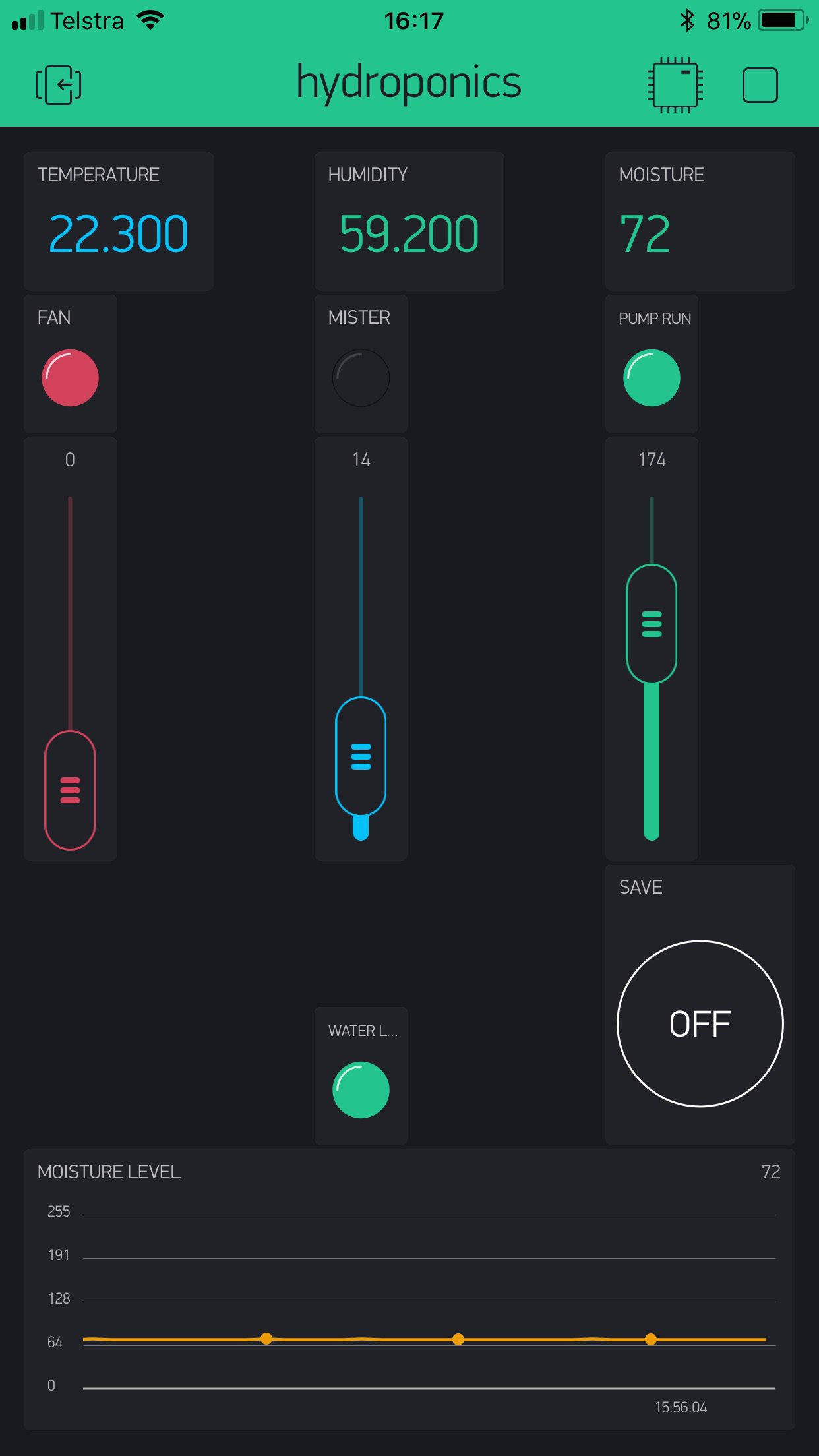
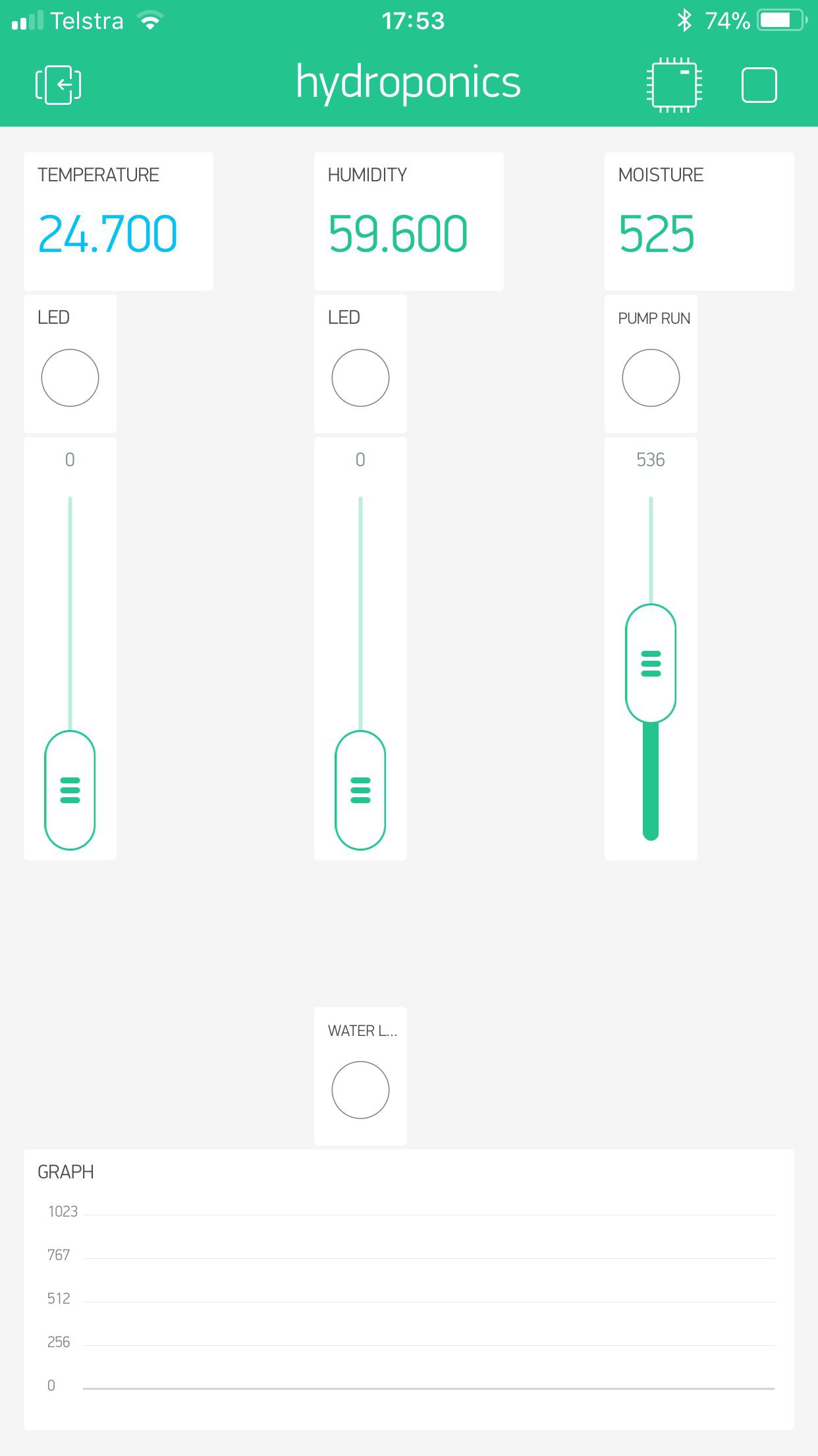
Ive put together a Blynk App to get the ball rolling and looks something like this
![]()
The Temp, Humidity and Moisture level will be displayed across the top of the screen the sliders below those will adjust the set point for each parameter.
The LED at the bottom is a warning indicator that the water resivior is low.
The Graph at this stage will display moisture level of the bed over time.
- Display
-
Slow Progress
12/13/2017 at 07:13 • 0 commentsHaving a couple of kids under 3 doesn't bode well for rapid development - They take up a lot of time.
So progress has been slow but non the less there has been progress.
Software has been started and the ESP8266 sends temperature, humidity and moisture readings to the Blynk App. just need to add the water level sensor value and thats the inputs taken care of.
Next step will be to take the setpoint parameters from the Blynk app for the fan and water pump activation that will have the software largely sorted.
once that is organised I will get to work on the hardware to control the fan and pump
-
Firmware development 1
11/17/2017 at 23:28 • 0 commentsNow I have the IO sorted out time to move onto making the firmware come together.
The basic frame work.
Read All the sensor values -
- Grow Bed moisture level (Moisture)
- Temperature (Temp)
- Humidity (Humid)
- Water level (WaterLevel)
Send Values to Blynk App.
If Moisture is low - Turn on the Pump for 6 minutes (the length of time it takes to flood the bed)
If Temp is above X level - Turn on fans
If Humid is below Y level - Turn on mister for 1 minute (this is an arbitrary value and will need tuning)
If WaterLevel is low - Set an Alert on the Blynk App.
Set points to be adjusted by Blynk
Temperature and Humidity readings displayed on the Blynk App
-
Lock Down
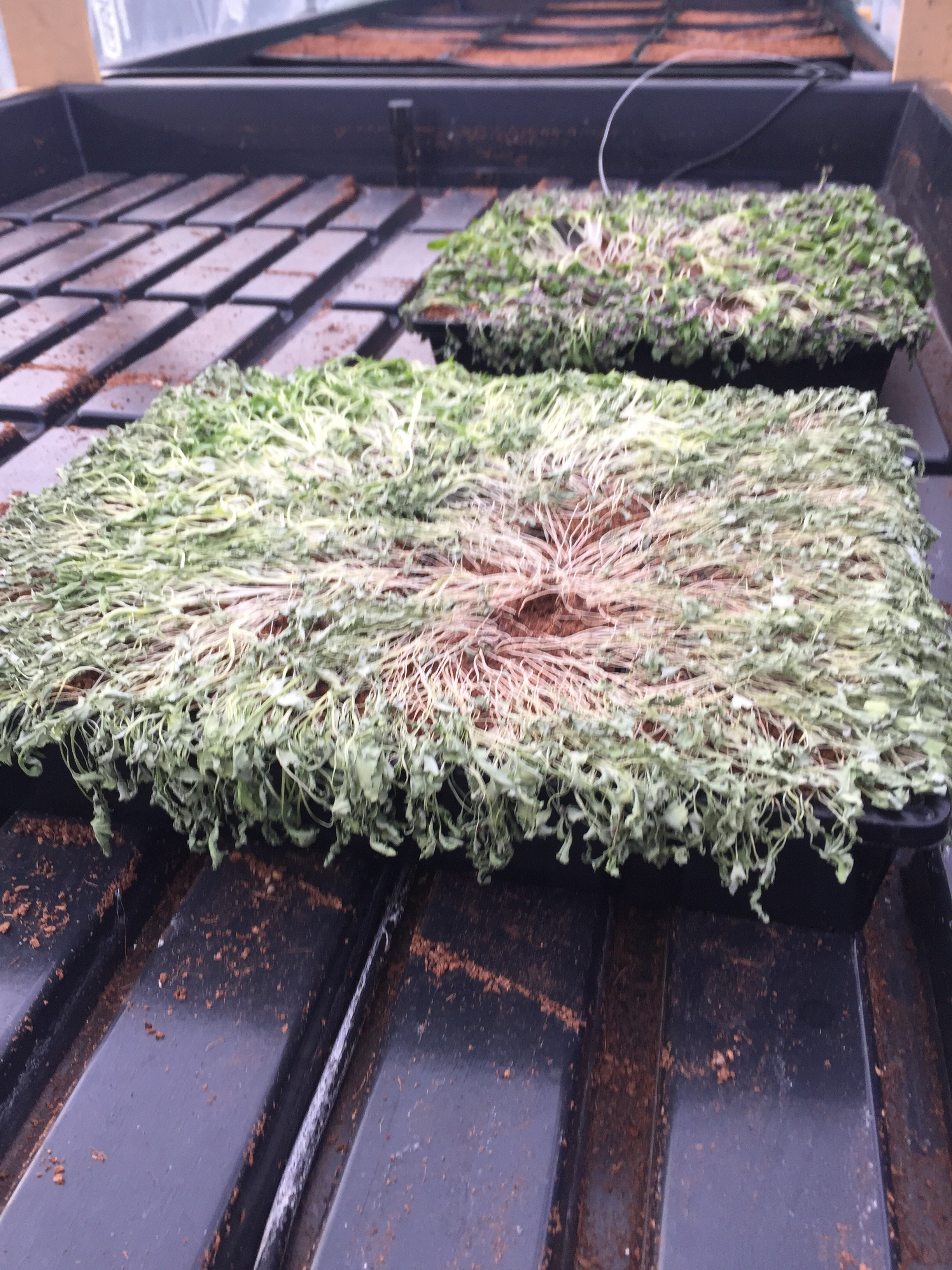
11/16/2017 at 19:31 • 0 commentsToday the project starts in earnest. I was contacted last night by my brother with a rather disturbing picture of dead plants.
![]()
Due to the unattended operation some failure occurred and with no monitoring of the system the grow bed was devoid of water for a period of time.
While contemplating the requirements of the project all manner of ideas have come up and what we could control and needless to say feature creep was starting to set in so a decision has been made to lock down the parameters just as indicated in the description above and save the added features for a future project and upgrade once we had the opportunity to try the system out. Implementing great ideas that may be not necessary will only delay the project further which will lead to greater crop loss.
The project in its current form will be limited to 3 inputs and 3 outputs
Inputs
Node MCU Pin Description Type A0 Grow media Moisture Analog D1 Water Storage Level Digital D2 Temperature and Humidity One wire Bus Outputs
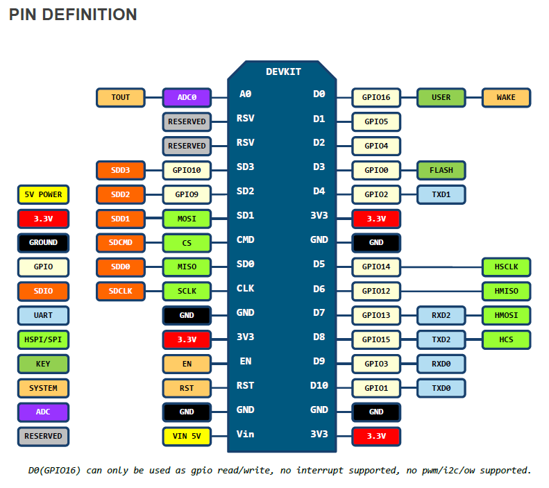
Node MCU Pin Description Type D5 Water Pump Digital D6 Exhaust Fan Digital D7 Mister Digital D8 Moisture Sense Activate Digital Specs for the NODE MCU 1.0 Board available from
https://github.com/nodemcu/nodemcu-devkit-v1.0
Pinouts
![]()
Hydroponics control
Automated control of hydroponics Garden with Control Via Blynk