zakqwy
-
ATtiny Izhikevich(ish) Dynamics, part two
01/31/2016 at 16:11 • 0 commentsToday, Hackaday.io, you will be my rubber ducky. This log will cover implementing a crude approximation of Izhikevich neuron dynamics on a really cheap Atmel processor. In case you missed it, I discussed his model in the previous log, along with all the silly ways I corrupted the math in an attempt to make it run faster on an 8-bit, 8 MHz microcontroller.
First, a quick pseudo-code overview of the firmware:
int [a whole bunch of global variables];
main() {
    SystemInit;
    for(;;) {
        waitforISR;
        checkDendrites;
        calcDendrites;
        calcMembraneCurrent;
        calcIzhikevichModel;
        if (firing) {fire;}
        calcLED;
        updateLED;
    }
}
The actual firmware is a bit more scattered since timing ends up being really important; in particular, the model calculations are broken into several pieces with LED updates in between to prevent flicker. If you want to see actual code... read on.
The complete v07 (again, more on that later!) firmware is here. I'll get it up on GitHub once I consider it "release-worthy".. I still need to debug a few timing issues with the 'scope. But feel free to check it out if you like. Below, I'll go over the non-commented portions, skipping the exhaustive intro that covers hardware and Izhikevich model outputs.
Global Variables
/*  Izhikevich model parameters and coefficients */
const int16_t a = 5;
const int16_t b = 2;
const int16_t c = -65;
const int16_t d = 8;
const int16_t E = 6;
const int16_t F = 2;
const int16_t G = 16;
const int16_t H = 161;
These are the parameters (a, b, c, d) and coefficients (E, F, G, H) that feed the membrane potential calculation model. Much more info on their derivation can be found in the previous update. I kept 'em in one spot so they're easy to change if I find better values. Note that these are all 16-bit signed integers, so maintaining atomicity will be a requirement for avoiding weird errors./* Izhikevich model variables */ volatile int8_t I; volatile int8_t I_rest = 21; volatile int16_t v = -65; volatile int16_t u = 0;These are the Izhikevich values that change every 'tick'. I gets set to I_rest at the beginning of the cycle before getting reset to an appropriate number based on dendrite states. v and u are the all-important membrane voltage and membrane recovery values./* Intra-model variables */ volatile int16_t vSq = 0; volatile int16_t vF = 0; volatile uint8_t modelStage = 0; volatile int16_t v_prev; volatile int16_t u_prev;Here's where stuff gets a little bit more interesting. One of the more computationally expensive operations required in implementing the Izhikevich model involves squaring the current value of v. I ended up breaking this, along with a few other parts, out of the main calculation to save time. The modelStage variable keeps track of where the model currently is in this process.
/*  Neuron variables */
volatile uint8_t firing = 0;
volatile uint8_t fireTimer = 0;
const uint8_t axonPulseLength = 5;
volatile unsigned char dendStatus = 0; //current status of four dendrites, including types
volatile unsigned char dendStatusPrev = 0; //previous dendrite status/type
volatile int8_t val_Dend[4]; //keeps track of current dendrite's contribution to I (positive or negative)
volatile uint8_t stg_Dend[4] = {0,0,0,0}; //current stage of each dendrite impulse: 0 is REST, 1 is HOLD, 2 is DECAY
const int8_t hldTime_Dend[4] = {20,20,20,20};
volatile int8_t hldTimeCur_Dend[4];
const int8_t hldVal_Dend[4] = {10,10,10,10};
const int8_t dec_Dend[4] = {2,2,2,2};
These are variables related to the state of the neuron, its inputs, and its outputs. firing toggles to 1 if the neuron is experiencing an action potential; once this happens, fireTimer increments until it hits axonPulseLength to ensure the output signals are long enough to trigger downstream NeuroBytes. The remaining variables and arrays keep track of the individual dendrites' contributions to I, and handle the hold and decay functions that make input signals semi-persistent./* LED variables */ volatile uint8_t LED[3] = {0,0,0}; //R,G,B, 0-100 volatile uint8_t LEDtick = 0; //0-100 volatile uint8_t LEDfade[3][61] = {//fader for -102 <= v < -41, where I=21 (v=-83) is rest (pure green). R,G,B {0 ,0 ,0 ,0 ,0 ,0 ,0 ,0 ,0 ,0 ,0 ,0 ,0 ,0 ,0 ,0 ,0 ,0 ,0 ,0 ,0 ,0 ,1 ,1 ,2 ,2 ,3 ,3 ,4 ,4 ,5 ,5 ,6 ,6 ,7 ,7 ,8 ,8 ,9 ,9 ,10,10,11,11,12,12,13,13,14,14,15,15,16,16,17,17,18,18,19,19,20}, {1 ,2 ,3 ,4 ,5 ,6 ,7 ,8 ,9 ,10,11,12,13,14,15,16,17,18,19,20,20,19,19,18,18,17,17,16,16,15,15,14,14,13,13,12,12,11,11,10,10,9 ,9 ,8 ,8 ,7 ,7 ,6 ,6 ,5 ,5 ,4 ,4 ,3 ,3 ,2 ,2 ,1 ,1 ,0 ,0 }, {19,18,17,16,15,14,13,12,11,10,9 ,8 ,7 ,6 ,5 ,4 ,3 ,2 ,1 ,0 ,0 ,0 ,0 ,0 ,0 ,0 ,0 ,0 ,0 ,0 ,0 ,0 ,0 ,0 ,0 ,0 ,0 ,0 ,0 ,0 ,0 ,0 ,0 ,0 ,0 ,0 ,0 ,0 ,0 ,0 ,0 ,0 ,0 ,0 ,0 ,0 ,0 ,0 ,0 ,0 ,0 } };These variables keep track of the current LED state and PWM "tick". The massive LEDfade[][] array is used as a cross-reference to determine appropriate R, G, and B values for each given v value; this gives me more flexibility than the v04 firmware (which used linear interpolation) if I want to tweak the colors a bit. You can see that I set the maximum LED brightness at 20%, which seemed about right during testing next to v04 boards./* Timing variables */ volatile uint8_t tick = 0; //ISR flips this to non-zero to update loop const uint8_t modelUpdateFrequency = 255; //how many ticks pass before the model recalculates (higher = slower) const uint8_t modelUpdateMultiplier = 3; //multiplier for modelUpdateFrequency (since they're 8-bit unsigned integers)Last set of global variables. These values are used for timing; when the timer interrupt service routine flips tick to a non-zero value, the program updates. modelUpdateFrequency and modelUpdateMultiplier are used to scale the speed of the neuron simulation; as you can see, I needed 765 (3 * 255) ticks to roughly match the v04 update rate. Yes, this means that NeuroBytes v07 can be used as a real-time biological neuron simulator which is extremely awesome.Functions
void getDendrites(void) {
/*  updates dendStatus to the current input value:
bit MSB 6   5   4   3   2   1   LSB
DEND    4   3   2   1   4   3   2   1
input   SIG SIG SIG SIG TYPE    TYPE    TYPE    TYPE
pin PB1 PB0 PB7 PD6 PB2 PD7 PB6 PD5
*/
    dendStatusPrev = dendStatus;
    dendStatus = 0;
    dendStatus |= ((PINB & (1<<PB1))<<6);
    dendStatus |= ((PINB & (1<<PB0))<<6);
    dendStatus |= ((PINB & (1<<PB7))>>2);
    dendStatus |= ((PIND & (1<<PD6))>>2);
    dendStatus |= ((PINB & (1<<PB2))<<1);
    dendStatus |= ((PIND & (1<<PD7))>>5);
    dendStatus |= ((PINB & (1<<PB6))>>5);
    dendStatus |= ((PIND & (1<<PD5))>>5);
}
getDendrites() works with a global 8-bit char called dendStatus, where the four least significant bits represent the four dendrite types (inhibitory or excitatory) and the four most significant bits represent the four dendrite statuses (high or low). I'll get into dendrite types more when I go over hardware--suffice it to say that each connector has four conductors (ground, power, type, signal) allowing upstream NeuroBytes and input modules to decide whether stimulus causes excitation or inhibition.
After saving the previous dendrite state into dendStatusPrev, the eight similar looking expressions use bitshift masks (such as 1<<PB7) to check various input pin states, then a further bitshift operation to store that state in the appropriate dendStatus bit. For example, the signal state of dendrite 3 is found in PB7 (i.e. Port B's MSB) but needs to be recorded in bit 5 of dendStatus; thus, the masked port read is shifted right two bits before getting incorporated into dendStatus.
void calcDend(uint8_t dend) {
/*  checks the dendrites and updates I based on hold and decay variables. function only runs on the
    dendrite indicated in the argument so it can be staged via updateModel(). */
    uint8_t inh = 1; //toggles to 0 if the selected dendrite is excitatory
    if (dendStatus & (1<<dend)) {
        inh = 0;
    }
    switch (stg_Dend[dend]) {
        case 0: //REST
            val_Dend[dend] = 0;
            if (dendStatus & (1<<(dend + 4))) {
                stg_Dend[dend]++;
            }
            break;
        case 1: //HOLD
            val_Dend[dend] = hldVal_Dend[dend];
            if (dendStatus & (1<<(dend + 4))) {
                hldTimeCur_Dend[dend] = hldTime_Dend[dend];
            }
            else {
                hldTimeCur_Dend[dend] -= 1;
                if (hldTimeCur_Dend[dend] == 0) {
                    stg_Dend[dend]++;
                }
            }
            break;
        case 2: //DECAY
            if (dendStatus & (1<<(dend + 4))) {
                stg_Dend[dend]--;
            }
            else {
                if ((val_Dend[dend] - dec_Dend[dend]) > 0) {
                    val_Dend[dend] -= dec_Dend[dend];
                }
                else {
                    stg_Dend[dend] = 0;
                }
            }
            break;
    }
    if (inh == 1) {
        val_Dend[dend] = -val_Dend[dend];
    }
}
calcDend(dend) is one of the few functions that takes an argument; in this case, you feed it the dendrite number (0, 1, 2, or 3 for 1, 2, 3, or 4.. ugh) and it only looks at that input. I haven't timed this function yet, but I did this anticipating the need to stage the function between LED update cycles.This function first checks to see if the currently selected dendrite is inhibitory or excitatory; if the latter, it sets the local variable inh to 0. After that, the function checks the stg_Dend array to see whether that dendrite is currently zero (i.e. contributing nothing to I), holding, or decaying. If the dendrite is stimulated, the stage is reset to HOLD and the appropriate timers are reset. Finally, the resultant value stored in the val_Dend array is negated if the input is inhibitory.
void calcI(void) {
/*  updates I based on current dendrite values */
    uint8_t i;
    I = I_rest;
    for (i=0;i<4;i++) {
        I += val_Dend[i];
    }
}
Sums the four dendrite contributions to update I as needed. Starts at the resting point for I, which is 21 in this particular version.void updateModel(stage) { /* This function updates the membrane potential (v) and recovery potential (u) variables based on the current I value. Since the Izhikevich model includes a reset check to determine firing, this function also updates the 'firing' variable to 1 when the neuron fires. The model uses 16-bit integer math, so interrupts are temporarily disabled to maintain atomicity. Execution time: 29.0 us max, depending on current stage. */ uint8_t temp = SREG; cli(); if (stage == 0) { getDendrites(); } else if ((stage >= 1) & (stage < 5)) { calcDend(stage - 1); } else if (stage == 5) { calcI(); } else if (stage == 6) { //17.4 us vSq = square(v); } else if (stage == 7) { v_prev = v; u_prev = u; vF = v * F; } else if (stage == 8) { //29.0 us if(v_prev > H) { v = c; u = u_prev + d; firing = 1; } else { v = v_prev + (vSq >> E) + vF + G - u_prev + I; u = u_prev + (((v_prev >> b) - u_prev) >> a); firing = 0; } } else if (stage == 9) { //28.9 us translateColor(); } SREG = temp; }This function stages various calculations through ten steps, each of which resolves in less than the time between LED update cycles (40 us). First, the function stores the current interrupt register into temp and disables global interrupts; this is used to maintain atomicity, as some of the math uses 16-bit integers. Next, the function does different things depending on the stage:Stage 0: update the current dendrite status using getDendrites().
Stage 1, 2, 3, 4: calculate the four dendrite contributions to I using calcDendrites(dend).
Stage 5: sums the four dendrite contributions to update I using calcI().
Stage 6: starts the Izhikevich calculations by squaring the membrane potential, v, and storing the result in vSq. The square(int) function also checks for 16-bit signed integer overflow, and if present, instead returns 32767.
Stage 7: continues the Izhikevich calculations by multiplying v by F, and storing the result in vF. Also stores the current values of v and u since both of the next calculations need to run with each variable.
Stage 8: finish the Izhikevich calculations by checking for a fire state (v > H) and either resetting the model or finishing the calculation of v and u. Note, again, that E, a, and b have been replaced with right bit-shifts (i.e. 1/n^2).
Stage 9: translate the current membrane potential value into LED values (shown below).
Finally, the interrupt register is restored to its previous value. Note that when Stage > 9, this function doesn't do anything.
void translateColor() {
/*  translates membrane potential (v) values into the RGB array
    resting membrane potential:
    v < -102        pure blue
    -102 <= v < -90     fade blue to green
    v = -90         pure green
    -90 < v =< -71      fade green to red
    v > -71         firing (pure white)
    Execution time: 28.9 us
*/
    if(v < -102) { //3.5 us
        LED[0] = 0;
        LED[1] = 1;
        LED[2] = 20;
    }
    else if((v >= -102) & (v < -41)) { //24.1 us
        LED[0] = LEDfade[0][(uint8_t)(v + 102)];
        LED[1] = LEDfade[1][(uint8_t)(v + 102)];
        LED[2] = LEDfade[2][(uint8_t)(v + 102)];
    }
    else {
        LED[0] = 20;
        LED[1] = 1;
        LED[2] = 0;
    }
}
This function checks the current membrane potential value and translates that into R, G, and B LED values using the massive LEDfade[][] array. Note that the green LED is always at least equal to 1, as shutting it off entirely (especially during hyperpolarization) is quite noticeable to the eye.void updateLED(void) { /* Updates the RGB LED based on the current membrane potential value. Uses PWM fading and global variables to figure out when the various elements should be on. Resolution controlled by LEDtick reset. Execution time: 5.6 us */ if(LED[0] > LEDtick) { PORTC &= ~(1<<PC3); } else { PORTC |= (1<<PC3); } if(LED[1] > LEDtick) { PORTC &= ~(1<<PC4); } else { PORTC |= (1<<PC4); } if(LED[2] > LEDtick) { PORTC &= ~(1<<PC2); } else { PORTC |= (1<<PC2); } LEDtick++; if (LEDtick > 100) { LEDtick = 0; } }Pretty simple one that executes quite fast (and quite often). Checks the global LEDtick variable and extinguishes the LEDs when it exceeds their setpoints. Also resets LEDtick at 100 cycles (well, 101 cycles...).ISR(TIMER0_COMPA_vect) { /* Makes ticks fire at a regular interval in the main loop. */ tick = 1; }Everyone says to keep these really brief, so the timer interrupt service routine just changes a single variable.void systemInit(void) { /* set up D1 */ DDRC |= ((1<<PC2) | (1<<PC3) | (1<<PC4)); PORTC |= ((1<<PC2) | (1<<PC3) | (1<<PC4)); //set pins = LED off /* set up dendrites */ DDRB &= ~((1<<PB7) | (1<<PB0) | (1<<PB1) | (1<<PB6) | (1<<PB2)); DDRD &= ~((1<<PD5) | (1<<PD6) | (1<<PD7)); /* set up axons */ DDRD |= (1<<PD0); DDRC |= ((1<<PC1) | (1<<PC0) | (1<<PC5)); PORTC |= ((1<<PC0) | (1<<PC5)); //set type pins /* set up Timer/Counter0 */ TCCR0A |= ((1<<CTC0) | (1<<CS00) | (1<<CS01)); //CTC, clk/64 TCNT0 = 0; OCR0A = 4; //loop time = 8 * (OCR0A + 1) uS TIMSK0 |= (1<<OCIE0A); //enables Output Compare Match A ISR /* misc */ sei(); //enable global interrupts }Mostly self-explanatory with comments. Sets all the registers--inputs, outputs, timer, interrupts, etc. Tick timing is controlled by the Timer/Counter0 Output Compare Match A register, OCR0A; as shown in comments, each tick duration is approximately 8 * (OCR0A + 1) microseconds.void fire(void) { PORTC &= ~((1<<PC2) | (1<<PC3) | (1<<PC4)); fireTimer = axonPulseLength; }Makes the LED flash WHITE when the NeuroBytes board fires. Also resets the fireTimer to hold axon outputs HIGH for axonPulseLength ticks.Main Loop
int main(void) {
    systemInit();
    uint8_t i = 0; //counters for update delay
    uint8_t j = 0;
    for(;;) {
        while(tick == 0) { /* idle loop */ }
        /* This stuff happens every 40 uS or so */
        tick = 0;
        if (i < 10) {
            updateModel(i);
        }
        if (firing == 0) {
            updateLED(); //5.6 us
        }
        else {
            fire();
        }
        j++;
        if (j == modelUpdateMultiplier) {
            i++;
            j = 0;
        }
        if (i == modelUpdateFrequency) {
            i = 0;
            if (fireTimer > 0) {
                PORTD |= (1<<PD0);
                PORTC |= (1<<PC1);
                fireTimer--;
            }
            else {
                PORTD &= ~(1<<PD0);
                PORTC &= ~(1<<PC1);
            }
        }
    }
}
This loop ties everything together. The main loop uses modelUpdateMultiplier and modelUpdateFrequency in conjunction with i and j, two local counter variables, to run updateModel() and iterate fireTimer when needed. Note the use of a while loop to take up all the tick slack; during testing, I can easily comment this line out, add in a debug pulse on an extra I/O line, and use my oscilloscope to quickly figure out the execution time for each stage.
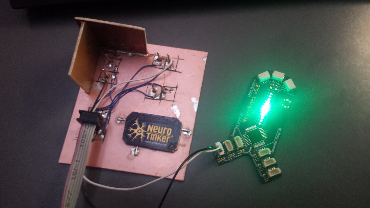
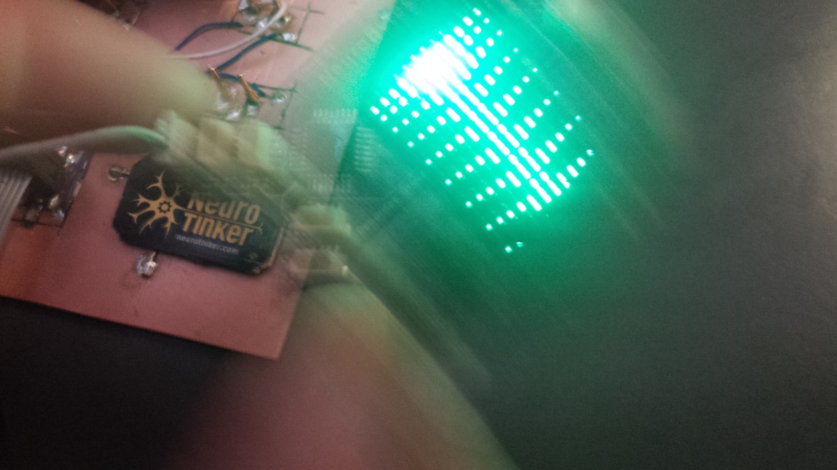
And here it is running on a pair of teeny v07 boards:
I'll get back to hardware next. Comments on the code are welcome!
-
ATtiny Izhikevich(ish) Dynamics, part one
01/28/2016 at 20:25 • 0 commentsI've been slacking on updates--turns out when you get to work on a project full time, it doesn't make logs magically appear. In any case, this log post will focus on one thing: improving the core NeuroBytes firmware. I'll bring ya'll up to speed on other stuff in the next few weeks.
If you ever took a look at the v04 code, you may have noticed that the neuron membrane potential decay algorithm was quite simplistic:
if (potentialTimerCounter >= potentialTimerOverflow) {
	decayPotential = (decayPotential * 95) / 100;
}
This pretty much takes the current value and multiplies it by 0.95. There were a few other snippets here and there that did stuff too--if the current potential was over 100, for example, the code called that a "fire", immediately dropped the membrane potential by _a lot_, and made the LED blink white. The resultant boards looked reasonably correct, but the model didn't respond quite as expected when stimulated at higher levels. Neurons also fired _immediately_ rather than ramping up over time. Other issues included an unacceptably low refresh rate, occasional atomicity problems, and general inflexibility--it wasn't possible to change individual dendrite weighting, for example. Time for a rewrite.In 2003, Eugene Izhikevich published a paper describing a computationally efficient method for simulating a variety of biological neuron types in software. His results were impressive: using a consumer-grade 1 GHz desktop PC, he was able to simulate a 10,000-element spiking cortical neuron network in real time with 1 ms clock resolution. A few years ago, @Bruce Land successfully implemented Izhikevich's model on an FPGA in his #Spiking neural net simulated on FPGA project.
![]()
Electronic version of the figure and reproduction permissions are freely available at www.izhikevich.com
You should probably stop reading this now and go read Izhikevich's paper, and then check out Bruce's project. In a nutshell, the model uses a pair of differential equations to keep track of membrane potential (v) and membrane recovery (u), along with a limit check that resets the model when the neuron fires. a, b, c, and d are parameters related to the specific type of neuron being modeled, while I is the cell's constant current input. As far as I can tell, these parameters were determined empirically based on observations of actual neurons, and the resultant model is quite accurate.
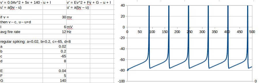
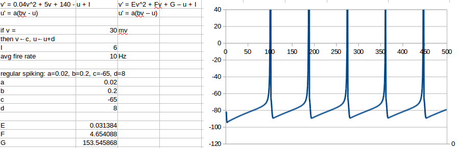
The first step was to recreate Izhikevich's model in a spreadsheet so I could wrap my head around the equations. This is what I eventually came up with, graphed over 0 < t < 500 ms:
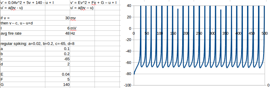
The sheet is actually pretty fun to putz around with--you can change the parameters as Izhikevich suggests to emulate different types of neurons, such as fast spiking:![]()
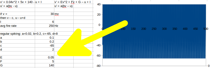
I also broke out I, as well as the original coefficients Izhikevich used in his differential equations; I called them E (the square coefficient), F (the linear coefficient), G (the offset coefficient), and H (the reset voltage threshold). They were also fun to putz with, although pretty much every minor change resulted in something like this:![]()
Disastrous results from a tiny change, as you can see. Maybe I shouldn't mess with the coefficients.![]()
So what's the issue? Why am I messing with the coefficients? Why not just copy the equations directly from LibreOffice Calc into VIM and call it a day?
In a word, speed. Remember, I'm trying to reduce flicker while PWMing three LED elements using an 8 MHz 8-bit microcontroller. Based on the LEDs I'm using and the desired dimming range (and a lot of waving test boards around), I need to update the LEDs every 30 us or so--that's 240 clock cycles. Since the ATtiny doesn't have anything resembling a floating point unit, everything also needs to be worked out in integers.
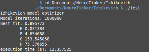
I tried adding int() tags in various spots in the equations, but I didn't get very far. The first coefficient divides the square of v by 25, and rounding the quotient inevitably caused huge errors. Once I started introducing these errors--even when I managed to make them pretty small--I began to realize just how delicate the balance between a, b, c, d, E, F, G, H, and I really was. Time for another computer program! Here's a test version that uses floating point math to prove out the concept:
... results:![]()
Yeah, I totally was going to try (E = 0.031384, F = 4.654088, G = 153.545868, H = 75.376656) next!![]()
The program is actually pretty simple. It selects four random coefficients within a predefined range, runs through the entire 0 < t < 500 sheet using Izhikevich's original equation format (and standard spiking neuron parameters), checks the "fit" of the result, and stores the best "fit" coefficients until it's run through an unreasonable number of iterations. It's a brute force approach that works well enough for floating point math, as shown above.
To produce AVR-ready code, I forced the program to use integers in its calculations. I decided to change Izhikevich's original equation a bit to hopefully speed up the calculation--namely, I changed E, a, and b to bitshift operations, meaning they're restricted to various n values in 1/(2^n). I also set up boundary conditions that prevent 16-bit signed integer overflows. Here's what I (eventually) came up with:
![]() It's far from perfect, but the important dynamics work properly--namely, changing the value of I causes the fire rate to increase or drop to zero, and there is a distinct (although not as clear as in the original model) inflection point before each spike. You can see a few "known good" coefficient/parameter sets I came up with--getting to these required fiddling with fitment weights quite a bit, so I wrote 'em down whenever they worked decently well. If you're curious/bored/etc, the complete program is here.
It's far from perfect, but the important dynamics work properly--namely, changing the value of I causes the fire rate to increase or drop to zero, and there is a distinct (although not as clear as in the original model) inflection point before each spike. You can see a few "known good" coefficient/parameter sets I came up with--getting to these required fiddling with fitment weights quite a bit, so I wrote 'em down whenever they worked decently well. If you're curious/bored/etc, the complete program is here.You'll also notice that I left a bunch of new parameters on the screenshot above, along with a second plotted line--those are part of the fitment parameters. The program selects a series of points on the membrane voltage plot where it thinks the neuron experiences an action potential; this is based on the rate of change of this value (the "slope threshold"), and defines the linear and firing regions. The "firing?" line helped me quickly select good slope threshold values. Once this point is selected, the program calculates four parameters, averaged across 0 < t < 500:
linear region slope avg (0.252)
linear region range pct (0.180)
fire ratio (0.132)
number of firings (6)
Combined, these four parameters roughly describe what a neuron membrane potential waveform should look like; the ideal values from Izhikevich's regular spiking neuron are shown above in parentheses.
Up next: implementation in AVR-C. Which is done and works rather well, but I have already written far too much for one log update.
-
v06 MP indicator fading
01/06/2016 at 15:48 • 0 commentsYesterday I put together a few functions that fade the twelve membrane potential LEDs using 6-bit BCM at 160 Hz:
![]()
![]()
A good deal of this was developed at various Minneapolis coffee shops filled with curious patrons asking me questions about green LEDs. I was happy to take a few tangents to discuss neuroscience. As demonstrated above, flicker is noticeable when the NeuroBytes are waved back and forth rapidly, but I don't think it's too bad; after all, these devices will generally be used on a static surface. 160 Hz is a decent bit faster than those annoying LED Christmas lights, after all.
The functions started with Nigel Batten's excellent BCM example. I liked how he used the 'tick' counter to trigger stuff in the main loop from the ISR, keeping the interrupt stuff brief. Most of the other code is different, as I'm dealing with a 3x4 LED matrix spanning three different I/O ports (A, B, and D) and didn't use a pre-encoding function. I'm not going to add this firmware to the GitHub repo at this point as it's far from finished/debugged, but I'm posting it here if anyone has any comments or wants to use it for something else (it's all GPL v3). My code has slightly improved since the v04 days, but I'm still learning the basics re: bit manipulation and speed. I also added a sweet ASCII diagram for I/O reference.
(note: I didn't add any commentary after the code block, so feel free to stop reading this post now)
/* NeuroBytes v06 test program Fading MP LEDs via BCM, attempt 2 Copyright 2016 by Zach Fredin zach@neurotinker.com This file is part of NeuroBytes v0.6. NeuroBytes v0.6 is free software; you can redistribute it and/or modify it under the terms of the GNU General Public License as published by the Free Software Foundation, either version 3 of the License, or (at your option) any later version. NeuroBytes v0.6 is distributed in the hope that it will be useful, but WITHOUT ANY WARRANTY; without even the implied warranty of MERCHANTABILITY or FITNESS FOR A PARTICULAR PURPOSE. See the GNU General Public License for more details. You should have received a copy of the GNU General Public License along with NeuroBytes v0.6. If not, see <http://www.gnu.org/licenses/> */ #include <avr/io.h> #include <avr/interrupt.h> /* /\ / \ / \ / \___________________________________ \ \ \ NeuroBytes v0.6 \ \ \ \ D D D D D D D D D D D D D A | | 1 2 3 4 5 6 7 8 9 9 1 1 1 P | / 0 1 2 | / / / / / ___________________________________/ \ / \ / \ / \/ */ /* Membrane potential brightness array Array dimensions: MP_brightness[cathode][anode] IND-A1 IND-A2 IND-A3 IND-C1 D1:[1][1] D5:[2][1] D9:[3][1] IND-C2 D2:[1][2] D6:[2][2] D10:[3][2] IND-C3 D3:[1][3] D7:[2][3] D11:[3][3] IND-C4 D4:[1][4] D8:[2][4] D12:[3][4] */ volatile uint8_t MP_brightness[4][3] = { {1,31,15}, {3,63,7}, {7,63,3}, {15,31,1} }; volatile uint8_t g_tick = 0; //flips to non-zero when time to update (via ISR) volatile uint8_t g_bitpos = 0; //which bit is currently being checked volatile uint8_t MP_currentAnode = 0; ISR(TIMER0_COMPA_vect) { /* This interrupt service routine makes ticks fire at exponential intervals. It also dwells on each interval for three (hopefully) equally-spaced iterations to set the three anodes. */ g_tick = 1; //fires tick in main loop TCNT0 = 0; //resets Timer/Counter 0 MP_currentAnode++; //iterates anode if(MP_currentAnode > 2) { //go to the next bit if we've hit all three anodes MP_currentAnode = 0; OCR0A <<= 1; //double the delay g_bitpos++; //move one bit left if(g_bitpos > 5) { OCR0A = 1; //reset the compare register to timer refresh rate (see TCCR0A) g_bitpos = 0; //go back to the LSB } } } void systemInit(void) { /* set up Timer/Counter0 */ TCCR0A |= ((1<<CTC0) | (1<<CS02)); //CTC, clk/64 TCNT0 = 0; OCR0A = 1; //presets Output Compare Register A TIMSK0 |= (1<<OCIE0A); //enables Output Compare Match A Interrupt /* set up membrane potential indicator LEDs */ DDRA |= (1<<PA3); DDRB |= ((1<<PB7) | (1<<PB6) | (1<<PB0)); DDRD |= ((1<<PD5) | (1<<PD6) | (1<<PD7)); /* preset all ports low */ PORTA = 0; PORTB = 0; PORTD = 0; /* misc */ sei(); //enable global interrupts } void MP_off(void) { //sets all cathodes, clears all anodes PORTD |= ((1<<PD5) | (1<<PD6) | (1<<PD7)); PORTB |= (1<<PB0); PORTB &= ~((1<<PB7) | (1<<PB6)); PORTA &= ~(1<<PA3); } void MP_setAnode(uint8_t anode) { //sets designated membrane potential anode switch(anode) { case 0: PORTB |= (1<<PB7); break; case 1: PORTB |= (1<<PB6); break; case 2: PORTA |= (1<<PA3); break; } } void MP_clearCathode(uint8_t cathode) { //clears designated membrane potential cathode switch(cathode) { case 0: PORTD &= ~(1<<PD5); break; case 1: PORTD &= ~(1<<PD6); break; case 2: PORTD &= ~(1<<PD7); break; case 3: PORTB &= ~(1<<PB0); break; } } int main(void) { systemInit(); uint8_t MP_currentCathode; for(;;) { while(g_tick==0); { /*blank idle code waiting for ISR */ } g_tick = 0; //consumes tick when routine starts MP_off(); MP_setAnode(MP_currentAnode); for (MP_currentCathode = 0; MP_currentCathode < 4; MP_currentCathode++) { if ((MP_brightness[MP_currentCathode][MP_currentAnode]) & (1<<g_bitpos)) { MP_clearCathode(MP_currentCathode); } } } } -
v06 prototypes (partially) working!
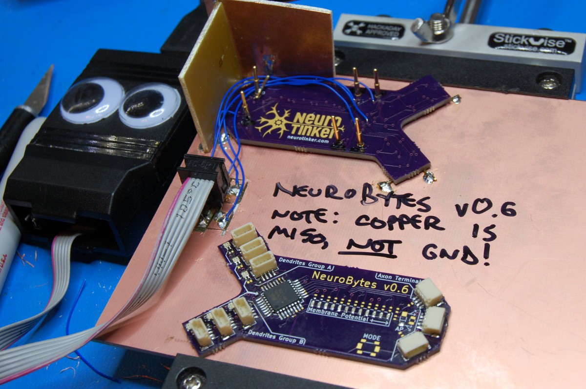
12/19/2015 at 17:05 • 5 commentsI'm still waiting on a few parts (namely 0402 dropping resistors for the LEDs), but I got one v06 prototype partially assembled last night--and I can talk to the ATtiny88, so I must have done something right with the design!
You may have noticed the six pads on the back of the board design--I wanted to try pogo-style programming, since that's what we'll use when we ramp production up a bit. I deliberately made the pad locations symmetrical along the long axis of the board, intending to use one of the six prototypes as a base for programming (along with some hastily soldered together FR-4 as an alignment rig):
![]()
[note: someone at the #Hackaday SuperConference 2015 gave me a few googly eyes that made their way onto my USBtinyISP. Who was that? Thanks!]
The note already tells you something is wrong; during handling I managed to snap off one of the pogo pins. Turns out 1.5mm diameter pads break pretty easily. It's the MISO pin, so I re-purposed the ground plane and added a "splint":
![]()
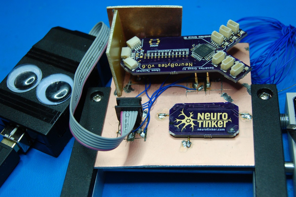
Hilarious but ultimately ineffective--soon after taking this picture I snapped another pin off. Lesson learned--use insertion-mount pogo pins and take the time to make a custom carrier board! In any case, I decided to mount the pins directly to the FR-4; I had to tweak the alignment of a few to get a reliable connection, but this setup worked. I made sure to give each pin a generous copper pad so it wouldn't break off as easily:
![]()
I also scavenged a NeuroTinker logo off the scrapped board. The solder mask pullback + ENIG copper logo turned out pretty well, so I figured it was worth highlighting.
Oh yeah, and I didn't remember to implement one of the important lessons I learned when I put together v04: 4-pad SMD LEDs are a PITA to hand-solder and including a bit of extra pad goes a long way. The red/blue dendrite LEDs check out with the continuity tester, but we'll see if they actually work...
-
FUNDING SECURED!
12/17/2015 at 21:03 • 10 commentsWe applied for a Phase I SBIR from the National Science Foundation back in June to develop the NeuroBytes platform and get it into a classroom. Today we found out that we've been awarded the grant! That means as of 1/1/2016, we'll both be working full time on this project! BOOM!
![]()
So yeah, excitement. I'm going to keep using this project page to document all the details related to the platform, so stay tuned. v06 boards just shipped from OSHpark!
-
v06 boards off to fab _soon!_
12/07/2015 at 21:38 • 0 commentsThey're different enough from the v05 prototype that I decided to iterate the version number.
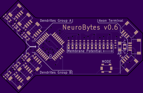
OSHpark renders:
![]()
![]()
Lots of new features:
- red/blue dendrite indication
- bargraph membrane potential indication
- surface mount connectors with finer pitch (1mm)
- right-angle connectors for axon terminal
- three axon connectors (vs 1)
- mode selection
- adjustable weighting/summation between dendrites in the same group
- pogo programming
- swanky logo/graphics
- directional board shape
- backpropagation
- multiplexed LEDs
- compatibility with v04 (with suitable adapters)
Price (obviously) has gone up, as has complexity. Some of the features will take significant effort to implement in firmware. Either way, we are quite excited. More to come!
-
Prototype gif + concepts for v05
11/24/2015 at 04:00 • 0 commentsI brought the v05 prototype to the Superconference and briefly showed it during my talk (then proceeded to zip-tie it to my badge and carry it around for the rest of the evening). If you missed that, here's a quick clip of the board in "neuron demo mode":
![]()
So... the finished product won't have a bunch of DIP switches on board, or a 0.1" spacing ISP header, or a bunch of varnished jumper wires everywhere. The blue LED (which is also red sometimes) won't stay on all the time; these indicators will be used to show which dendrites are excited or inhibited, probably pulsing with brightness proportional to input weighting.
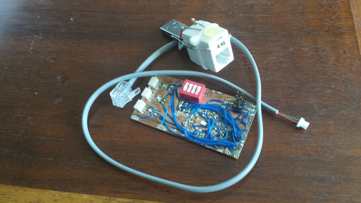
Beyond the LEDs, that's the other big change--input weighting. I'm also planning to use 4-pin connectors, so we can implement a backpropagation mode that actually changes individual dendrite weightings based on sequential firing. We've got a bunch of other ideas similar to this, but operating modes really are the key bit. Another shot, including the completely useless (well, beyond its current use) USB power adapter I put together:
![]()
I used the RJ11 (phone handset) cord because it's the only cable I had on hand that (a) was multi-conductor, and (b) had an O.D. close to the JST connector spec. I tried my usual rainbow ribbon cable and it split the connectors apart. I kept the phone plug on for, uh, modularity? Seemed silly to just cut off a perfectly good connector...
Briefly, here's where the v05 schematic stands:
![]()
It's anything but finalized, so I'm not quite ready to push this to the repo as a final product. In any case, I really like having eight indicator LEDs, and we both feel that six dendrites and three axons is ideal. I want to do some fancy dimming stuff with the LEDs so I'd prefer to avoid the complications related to multi/charlie-plexing, so I dropped a few of the R/B dendrite LEDs in favor of membrane potential indicators. This will actually work pretty well--we're planning to group pairs of dendrites together for one of our operating modes, so sharing a single R/B LED between two inputs makes sense. I also switched to a bunch of resistor networks, because 25 0402 resistors seems like a super pain in the ass to deal with.
Layout is still a work in progress. As promised, the new version is going to look more neuron-like than the square boringness that was v04. Further work will likely wait until after turkey day, so stay tuned...
-
v05 Prototype
10/31/2015 at 06:12 • 0 commentsMore to come...
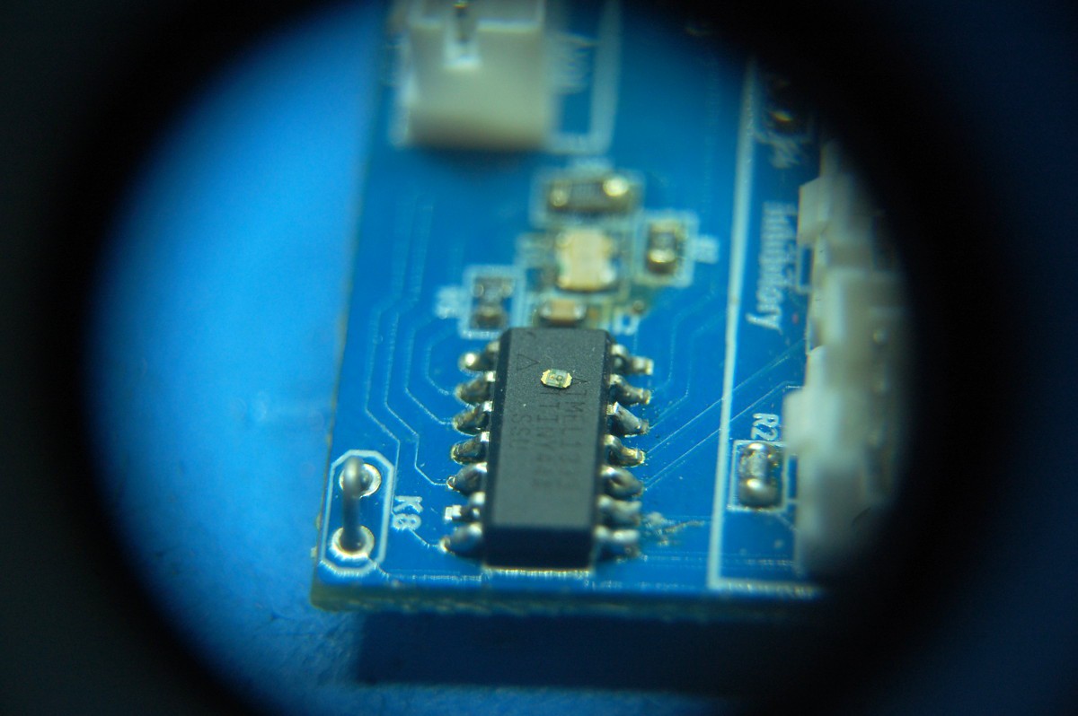
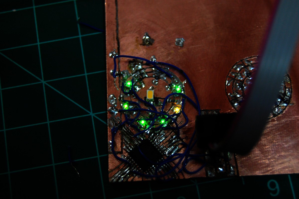
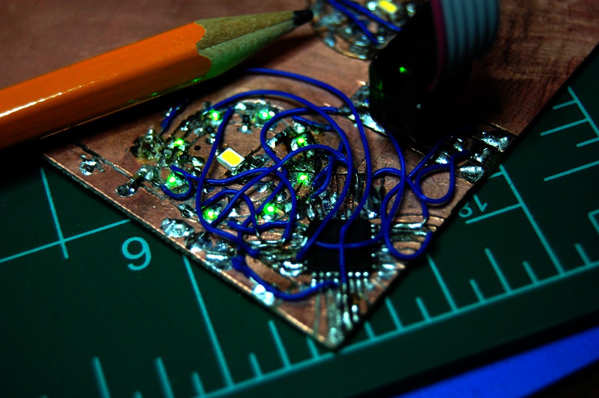
We're thinking about a different lighting scheme, one that involves a bunch of tiny LEDs. Green LEDs. Tiny green LEDs. I've never worked with 0402 stuff before. It's easy to lose (shown photographed through a loupe):![]()
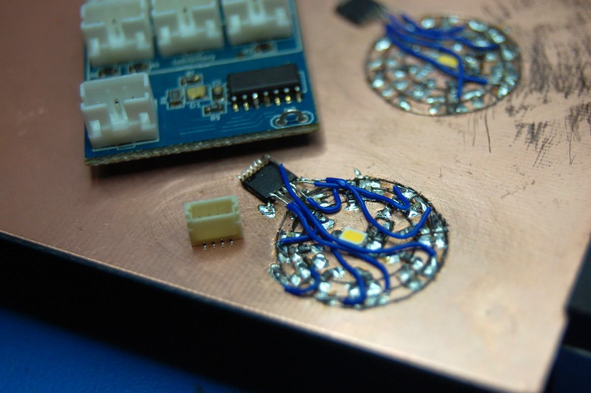
I ordered 25 LEDs, lost/destroyed the first couple, then tried to connect them to a dead-bug shift register (top right). During testing I fried a bunch of the LEDs, and the Dremeled trace work wasn't consistent enough to really function, so I tried again (bottom). Dead-bug plus 0.65mm pin spacing was tough to get working. Also shown: tiny connector!
![]()
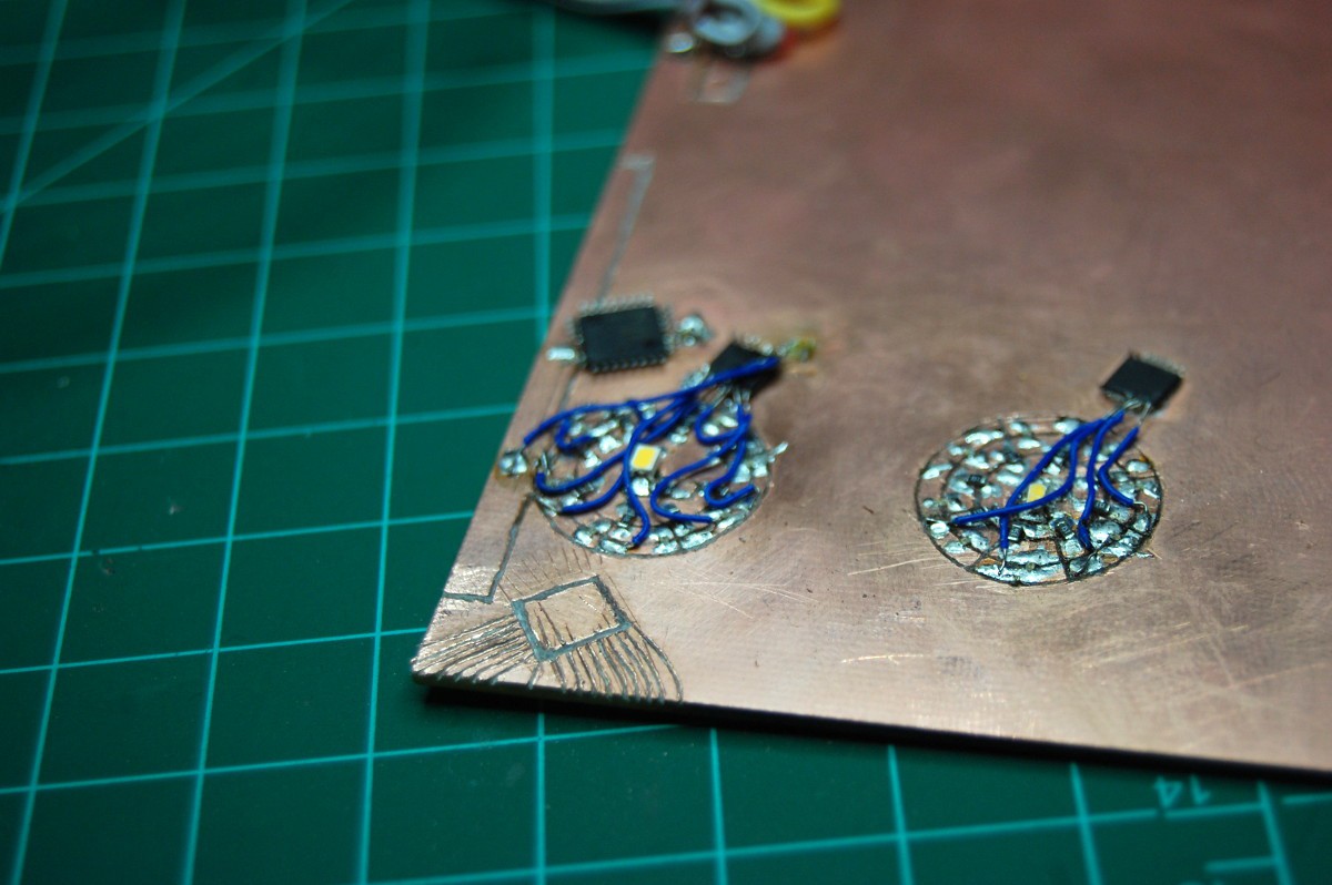
Time to shift gears, skip the shift register (note the attempted dead-bug ATtiny88, also abandoned), and mount the microprocessor right-side-up. X-acto trace time!
![]()
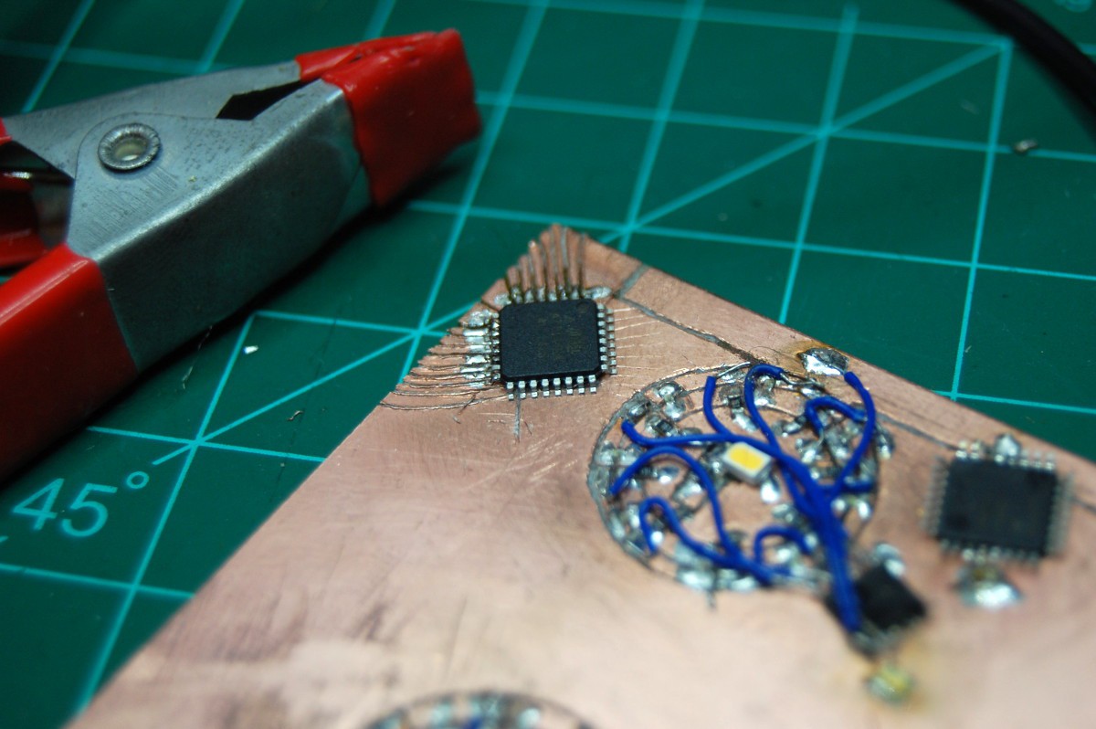
This chip is a bit more forgiving at 0.80mm, but I still had trouble with alignment. To make sure the pins lined up, I soldered the device halfway to the board and carefully cut the remaining traces using the installed chip as a guide. Not shown: an unbelievable number of continuity tests:
![]()
After finally getting the damn processor to listen (more continuity checks!), I toggled the LEDs on and hit a few snags. One was wired to the RESET pin (dumb) so I temporarily disconnected it, and another had a short. But more importantly... one was also the wrong color:
![]()
The LED worked but the single yellow element really bothered me. I was (and still am) also bothered by the fact that I pulled all the LEDs out of the same tape, meaning there was a sorting issue at the factory. At this point the LEDs I hadn't soldered down had pretty much all evaporated off my workbench due to moving air currents, so I had to desolder one from the other ring (which took 5 tries to get right). Finally done:
![]()
To do: dendrites, axons, more indicators, and a bit more time defluxing. Also programming, I suppose.
-
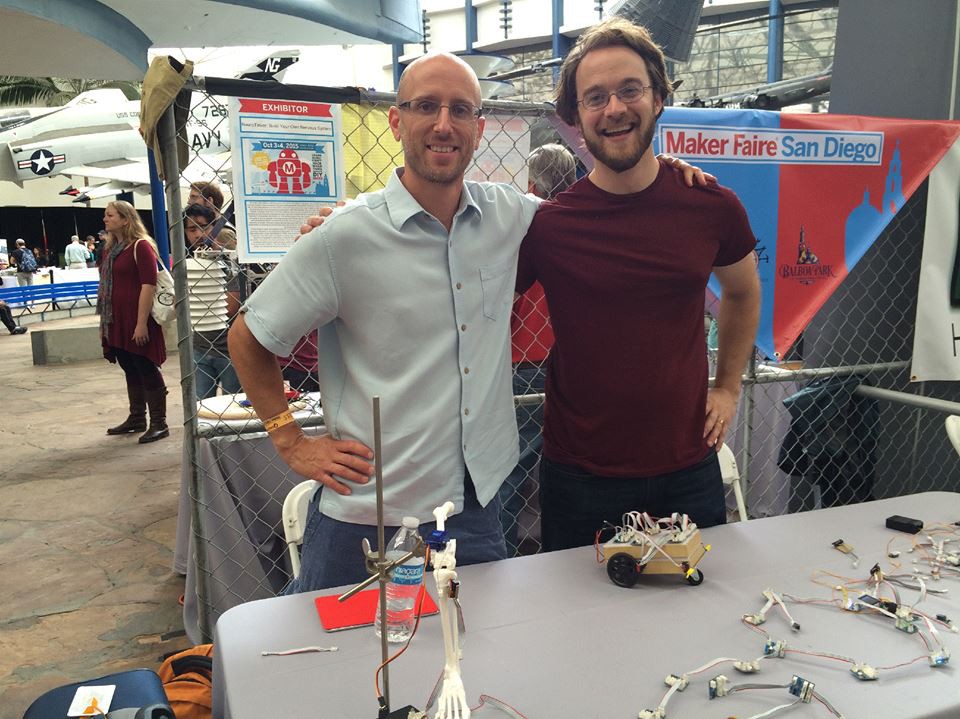
Joe and Zach Meet for the Second Time
10/06/2015 at 10:34 • 2 commentsWorking 1000 miles apart isn't so bad with stuff like Google Video Chat. But it was still great to spend the weekend at San Diego Maker Faire!
![]()
If you missed the show, we'll be back next year--it was an amazing experience in a beautiful city!
-
Hackaday Prize Best Product Finals info
09/21/2015 at 20:42 • 0 commentsThe Prize rules are somewhat particular about requirements, so I figured a dedicated project log that puts everything in one place might be helpful.
Video
Create a video, between five (5) minutes and ten (10) minutes in length, that shows a completed, working prototype with a market-ready product design/look and feel. The video should describe the problem it is solving and demonstrate how it facilitates the solution. The video does not need to be “studio quality,” but it should “sell” the project to non-technical viewers. Upload the video to YouTube or Youku and tag the video with the keyword: HackadayPrize, finals.
Project ProfileLink to the new video.
See above. It's also the bottom link on the project sidebar.
Update and add detail to info entered at the previous stages.
We've updated the Details section on the main page; that's probably your best bet to see exactly where the project stands today. A good deal has happened since the first THP2k15 deadline (8/17/2015):
- We created and shared a lot more NeuroBytes operating and test modes.
- We got lots of excellent feedback on the platform from the Game Maker's Guild.
- We interfaced NeuroBytes with a MeArm and a multichannel touch sensor [video].
- We were accepted to display at San Diego Maker Faire, 10/3 - 10/4.
Show at least twelve (12) Project Log updates.
If you want a complete and unfiltered history of the project, your best bet it to start at the beginning.
Post a components list that is complete with a bill of materials for one unit.
See the main project page, or click through to the components list. This includes everything needed to build one NeuroBytes v04 board and one Axon. You can also check out the BOM on GitHub, which adds in a few more Axons and includes old product links.
Post reproducible build instructions.
See the main project page, or click through to the build instructions.
Document complete schematics.
See this image from the gallery, or grab the Kicad files from the GitHub repo.
Post high resolution photos of the project inside and out. Include Gerber files (req - RS274 / RS274X), STL files (opt), netlist (opt), nc drill files (req - human readable), ODB++ (opt), STEP (opt), PCB files (opt), or any other design files.
Grab the Gerbers from the GitHub repo. Other design files (firmware and hardware) are elsewhere in the same GitHub project.