pastcompute
-
Dodgy data logger
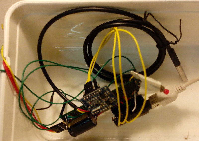
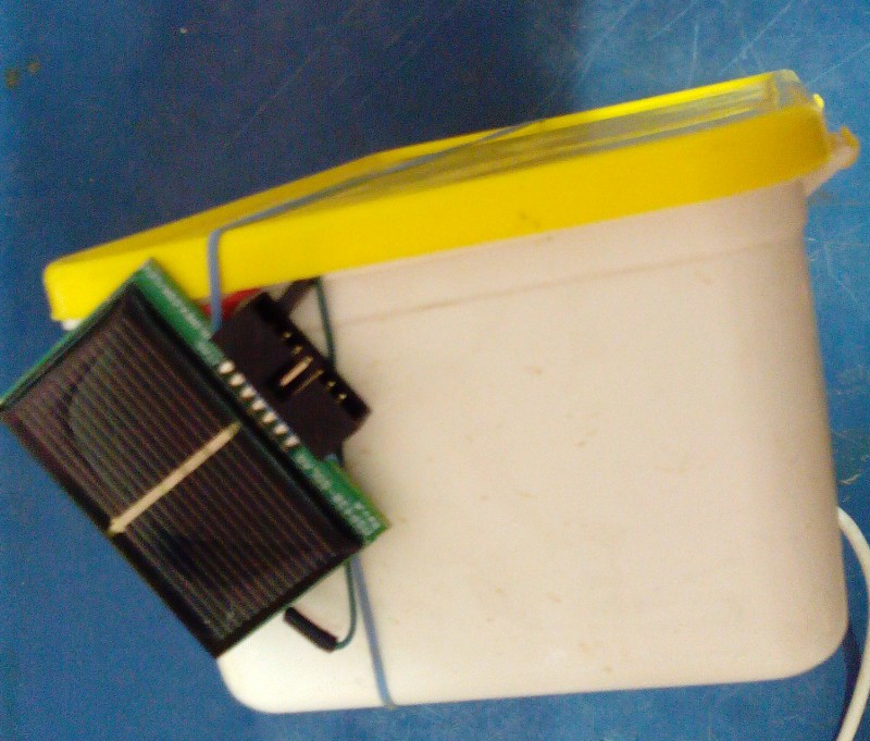
04/05/2015 at 13:12 • 0 commentsSo I managed to build a data logger over the weekend from an Arduino Leostick, a TinyRTC, DS18B20 and MSP430-SOLAR. In the end I didn't need the opamp, after verifying that the solar voltage definitely capped out at about 2.5V. So it monitors four voltages: Solar Panel, SuperCap, input to the stepup regulator (and thus the capacitor current) and the regulated 3v3. Also logs temperature and time.
As part of this exercise it struck me that I probably had to high a current limit resistor on the supercap as on examination the MSP430 features two diodes that drop up to 0.8V, presumably for limiting charge voltage to a NiMH or NICAD.
At also occurred to me that many small solar charge systems are simple but inefficient. Due to the diode there would be energy at low light that gets "lost", and further energy is lost through current limiting resistor on discharge. Ideally there would me some kind of MPPT between the panel and the supercap and the step up regulator (or perhaps all built into one)... so possibly some work to do here in a couple of months after the first system prototype is going.
Anyway, pictures of my dodgy work :-) Its been a while (read: a few years, apart from the radio miniconf at LCA2015) since I had the soldering iron warm for this long. I probably should have stuck to breadboard I would have been done a few hours earlier. But it tuns out its like riding a bike...
![]()
![]()
(Photos (c) @pastcompute CC-BY-NC) -
The real world
04/02/2015 at 13:41 • 0 commentsI caught up with one of my farming mates at the footy club tonight.
He definitely thinks this is a good idea. He also gave me some good insights:
- for example, some have weather logging devices on their headers (tractors) . But that only tells you whats going on where you already are...
- some paddocks would need more than one sensor - sometimes they measure the conditions then drive to the other side and things are different
- there is a community network where farmers are on the radio to each other. So perhaps there could be a 'cloud' layer over the top of the sensor network / farm base in the future...
- and of course you can buy remote water logging for troughs, for example, but they use the GSM/3G network - which means more SIM cards to maintain...
- with the fire danger there is the important 'delta T' calculation - more on that later
-
Solar characterisation
04/02/2015 at 13:38 • 0 commentsAccording to https://nurdspace.nl/ESP8266#Ultra-low_power_technology in deep sleep the ESP8266 needs 33mW and ~ 660mW while transmitting, so if I can use a 95% duty cycle then the average might be 65mW. Very roughly...
Again, very very roughly, because I haven't yet sat down and performed all the calculations including charge time at peak sunlight (2.4V @ 80ma), through the protection diode, taking into account the capacitor needs a current limit resistor, etc. plus current for the actual load.
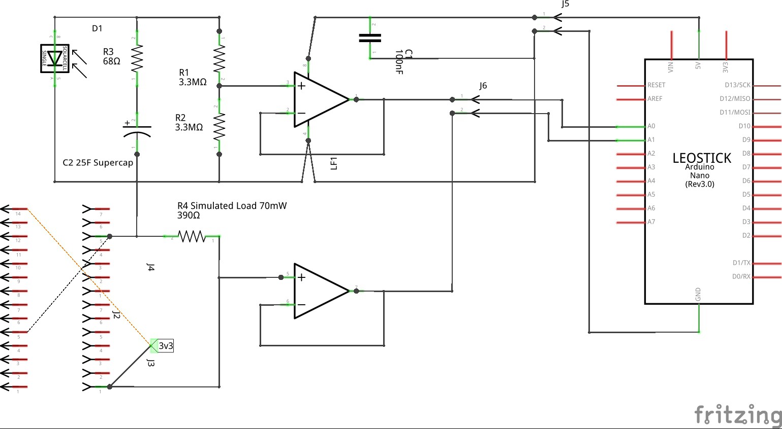
I'll probably do those properly eventually, but in the meantime I am building a datalogger to gain an empirical understanding of how the MSP430-SOLAR coupled with a 25F supercap deals with a 70mW load such as the ESP8266 might apply. This will give me some concrete results incorporating all the various inefficiencies, etc. - though still an approximation.
The data logger will log over 24 hours the solar cell / supercap voltage, plus the regulated 3v3 line, to gain an understanding of how low the supercap can discharge before the stepup / regulator flakes out.
Then I'll repeat with a real ESP8266 instead of a resistor...
(OTTOMH 95% charge is three time constants, or 25F, using a 68ohm current limit, or 85 minutes from empty to charged in full sunlight. Maybe. From the other end, at 75mW I ended up with a quadratic which is probably wrong given the time of night, but if we assume the supercap charged to 1.6V then the equivalent load is 397 ohms. Maybe. For a discharge time constant of 3.22 hours predicted, which is only part way through the night. So we shall see...)
Test circuit:
![]()
![]()
-
Fritzing around
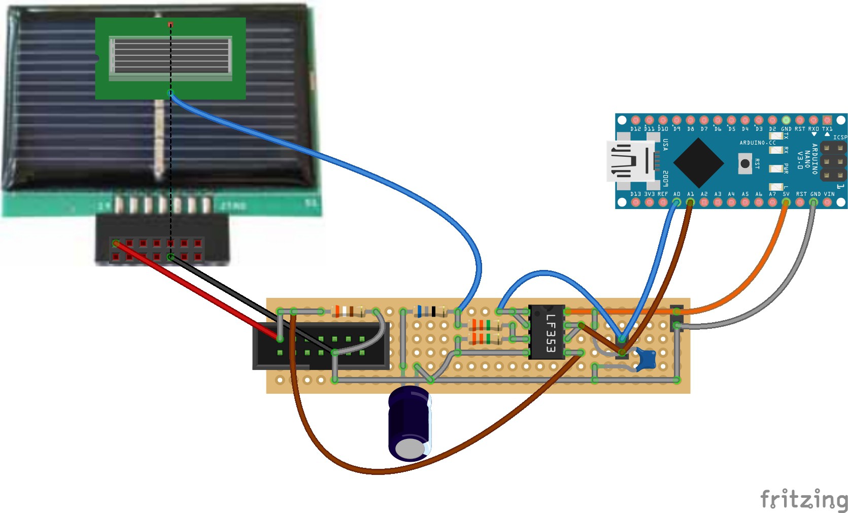
04/01/2015 at 12:44 • 0 commentsI took Fritzing for a test drive for the first time. After some stuffing around I managed to build it from the git sources on Debian wheezy, I updated their wiki with instructions for that case.
I found it very easy building up a circuit on the breadboard.
However, I found the schematic editor took quite a bit of getting used to, and the auto router just makes completely illogical decisions and added crazy crooked lines all over the place. In the end I just dragged the components around and manually edited the connections, once I worked out that you can just double click to make a bend. Along with a bunch of other UX annoyances I think there is still some polish but it is a useful tool for a quick circuit whip-up anyway.
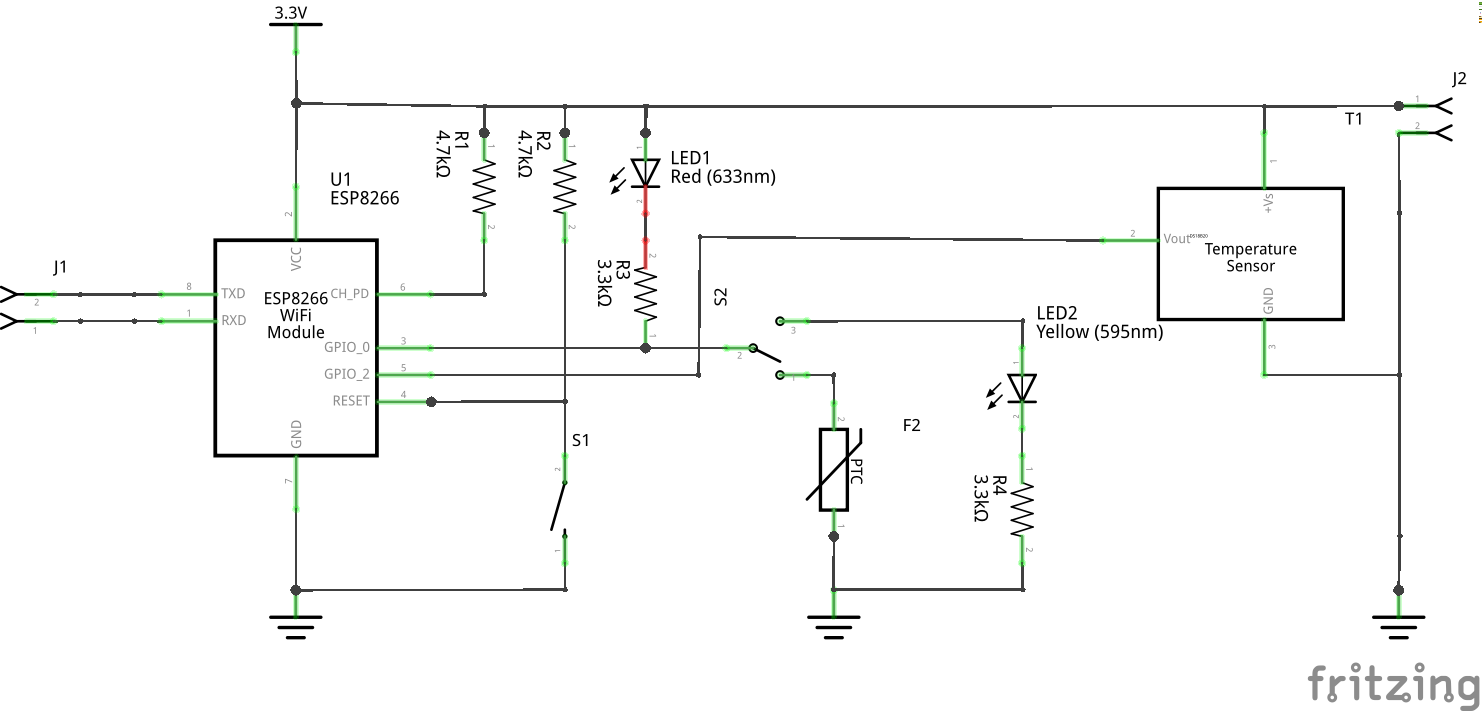
So here is the circuit for my desktop testing rig.
![]()
I can use this to develop and test the telemetry.
The ESP12 arrived today from tronixlabs and the MSP430-SOLAR from dontronics so over the weekend I'll hook those together and start experimenting with deep sleep mode and solar operation, to characterise power usage performance.
-
Sensor : mechanical design doodles
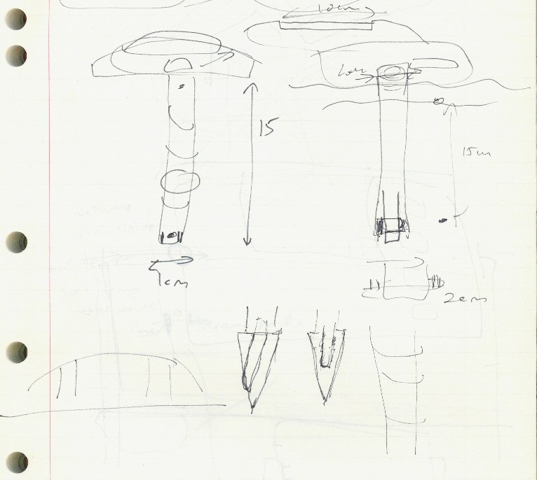
03/29/2015 at 12:08 • 0 commentsWe started thinking about the sensor mechanical fabrication today. It needs to be robust, moisture resistant, corrosion resistant, able to be pushed / twisted by a human into possibly compacted ground, and maybe even driven over. The shaft at this stage may be up to 20mm aluminium tube, with 3D printed bushes at each end and threading to accept a possibly ABS 3D printed structure housing the electronics and solar panel. The shaft may even have a auger incorporated
The image shows also our thoughts about how the DS18B20 sensor end be in ground contact, perhaps via a fabricated tapered aluminium block and heatsink grease.
![]()
-
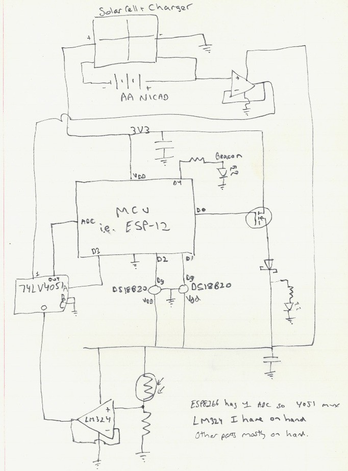
Ground sensor : circuit rough cut
03/29/2015 at 06:04 • 0 commentsFirst draft of ground censor circuit. It can monitor the battery voltage, ambient light. surface and subsurface soil temperature. The sensors are powered off, only enabled by the MOSFET to take readings; this will reduce standby power use and also interference when transmitting wifi. The beacon LED can be used to locate. I happen to have LM324 on hand so using that to buffer the analogue readings, and a 4051 to multiplex because the ESP8266 only has one ADC. The LDR monitors light, so we can transmit readings less often overnight to reduce battery (and logging the daylight will also be interesting) - and maybe helpful for diagnostics and tuning, because the solar panel may be partly obscured by a crop.
![]()
-
Small steps
03/28/2015 at 15:26 • 0 commentsI now have a full sensor hello-world built on top of esp8266-frankenstein. With the plumbing out of the way I can develop the sensor software.
I also came up with a better name : "SentriFarm". Github repository renamed accordingly. -
Deep Sleep, RF and other matters
03/26/2015 at 11:17 • 0 commentsThe next step on my critical path is evaluating the ESP8266 deep sleep mode. So to that end I have ordered an ESP-12 so I am waiting for that to arrive now.
For back to farm communication I am also researching the use of 433/915 MHz ISM band modules, which with the right antenna I should get 5-10-20km line of sight. It would be handy to ave a system that doesn't require the phone network. I think with the right controller setup in the fence posts, they can all act as store and forward / redundancy - it wont be a mesh - and I'm informed the ISM band comms works best over point to point.
-
More planning: interative agile design
03/26/2015 at 11:02 • 0 commentsI have a pretty good stash of various parts so I'll be aiming to build the first prototype mostly out of gear on hand. This means it will probably look pretty ugly or be using obsolete transistors or whatever but it will get the job done.
I'll be using a Carambola2 for the Fencepost Station prototype because I have one on hand, and it runs OpenWRT, which will migrate well software-wise if I end up choosing the
WRTnode I am currently considering to drive the whole thing. And so-on.This should mean that pretty soon there should be a cobbled together system actually running, then it will be time to look at spinning PCBs or making a well-designed enclosure. Perhaps some sponsors reading this might be able to help out at that point ;-)
Also there may be a lead time on some parts but I don't want that holding up prototype development. -
Housekeeping
03/22/2015 at 01:44 • 1 commentSo I just realised there seems to be no easy way to back up this area. Also I might be in danger of flooding too much information.
I think I'll need to do some housekeeping and tidying soon; I'll possibly start putting the design information into the git repository instead with a summary here, and for extended project logs I'll probably use my block for extended detail and link to there with shorter updates...
SentriFarm
Solving a key farming problem: is it safe to harvest / spray / sow today? (+experiments with 'big' data in agriculture)