Close
0%
0%

LD320EUN 32" Display for RasPI

I salvaged a LD320EUN 32" Display without any connection.
The Project : make it a display monitor

Similar projects worth following
I salvaged a 32" Display that would have gone to the trash. What a waste !
Could that become my next RaspBMC Display ? 32" sounds nice !

The display is not connect to anything, it has only the LDC Controller and the Back-light Controller.

Doing some search on Google, I found the LG LD320EUN datasheet which is a must have. I would have had a lot of difficulties without proper documentation. The display interface is dual channel LVDS. There is some option to connect to such interface, either a manufacturer boards like the Nitrogen6_MAX or a HDMI converter. There is not a lot of boards with dual channel LVDS output and they are not cheap. Since I had no clue if the display was even functional, I didn't want to invest to much in it. The cheaper and more flexible alternative is a HDMI converter. Ebay has a lot of LCD Driver Adapter Board but support and documentation is little. I selected the HDMI to dualLVDS converter. chalk-elec.com has documentation about their product and good support and how-to guides.

First things first, I tested the display to see if anythings was alive in the LCD Driver board or Back-light Controller. I should have tested the display before ordering anything but we get carried away sometimes. The Back-light doesn't work by itself as the back-light PWMs are controlled by the LCD Driver board. When both are powered, the back-light lights up. Since the display just need some signal, the next thing is the LVDS connector.

The LVDS connector on the cable of the LCD Driver is a 30-pin connector ( 2 Row x 15 pin ). BTW, If anyone knows the type of connector that is, I would like to know. I wish I knew to what board it was connected before, it could have gave me a clue about things. The tricky part is the dual channel LVDS matching, the LD320 datasheet has the LVDS signal described as follow : First Data Pixel 0,0 Pixel 2,0 and Second Data Pixel 0,0 Pixel 2,0 therefore I assign First LVDS channel to Even pixel and Second LVDS channel to Odd Pixel. The datasheet also describe the LVDS Clock to Clock Skew (Even to Odd) which collaborate the assumption. I planned to crimp connectors the LVDS cables but the old connector pin match the new one, that make it easier. The result of the cabling is the picture with Mordor like writing. The good thing is that pixels are being displayed on the screen. The disappointment is that odd and even pixel of each line are interverted.

I carefully reviewed the documentation and thing seems to be in order. How come pixels are not in the right order ? The answer I could come up with is that the DS90C387A datasheet use pixel numbering from 1 and the display datasheet count pixels from 0. Anyway I had to undo the connector I just did without breaking the plastic tab latching the connector in the housing (Messed up 2 out of 20, not too badly thought !). With LVDS channels matching, raspberrypi pi login displays clearly :).

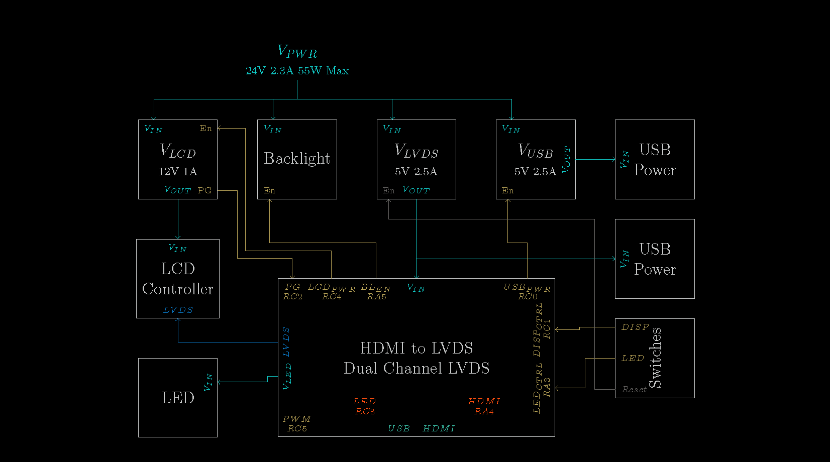
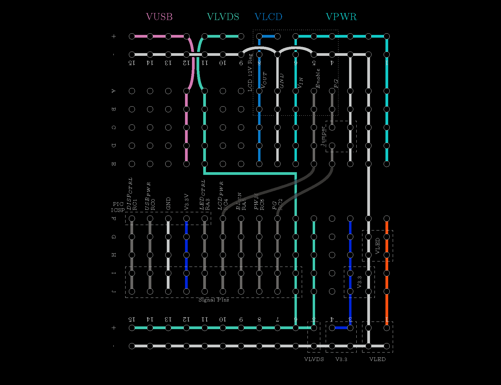
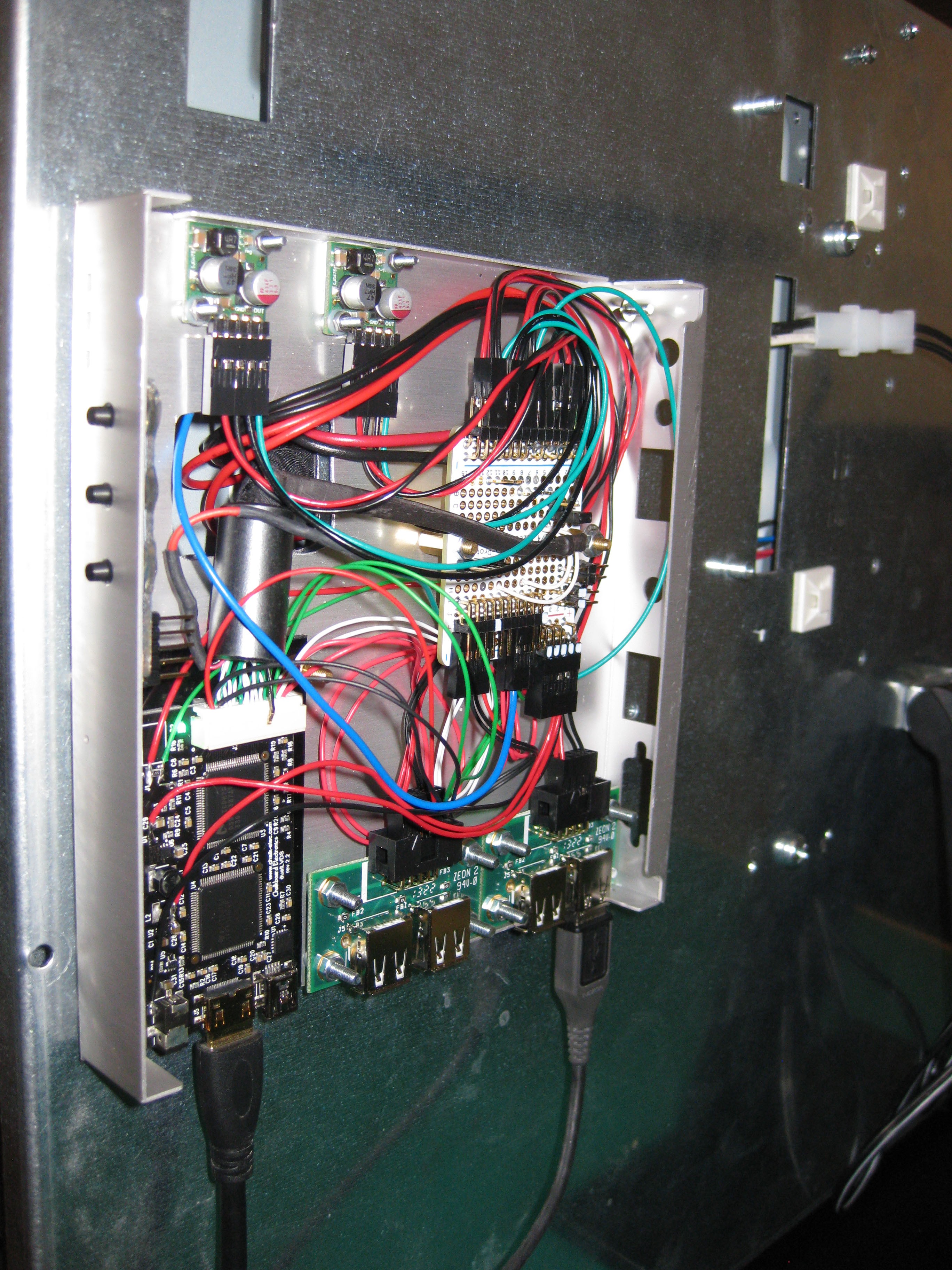
With the display working correctly, the cabling could be done correctly. The HDMI to dualLVDS converter has a PIC16F1455 micro-controller integrated. It enabled the converter outputs when HDMI signal is present. The goal is to have the back-light controller ON/OFF pin controlled by the micro-controller so when the HDMI is disconnected the display turns off. I'm using a breadboard PCB to connect the signal of the HDMI converter to the screen signal. Space is left on the breadboard for improvements :

  • The display is currently powered by a 24V power supply. There is a 24V to 12V DC-DC converter rated at 120W. I'm not going to use 10A @ 12V for the LCD Controller. I'll change that for a smaller buck converter matching the LCD Controller power requirements.
  • LCD Controller should be enabled only when HDMI signal is present, that will reduce power consumption in sleep mode.
  • The HDMI Converter is using an external 5V power supply. Add a 5V buck converter to power the adapter. That power supply could also power the Raspberry Pi either via the PIC16F1455 USB or a direct line.
  • On the HDMI to dualLVDS converter there is a back-light boost converter. It is not suited for such a display but I could drive a LED strip and make TV Dynamic...
Read more »

  • 1 × LD320EUN LG LD320EUM 32" Display
  • 1 × RaspberryPI RaspberryPI to use the screen, flash the edid
  • 1 × Lab Power Supply I need 24V, 12V and 3.3V to test the display. With the lab power supply, I can monitor/limit amperes
  • 1 × Soldering Iron
  • 1 × Crimp Tool Engineer PA-09

  • LVDS - VESA / JEIDA

    Stanislas Bertrand09/06/2016 at 17:58 0 comments

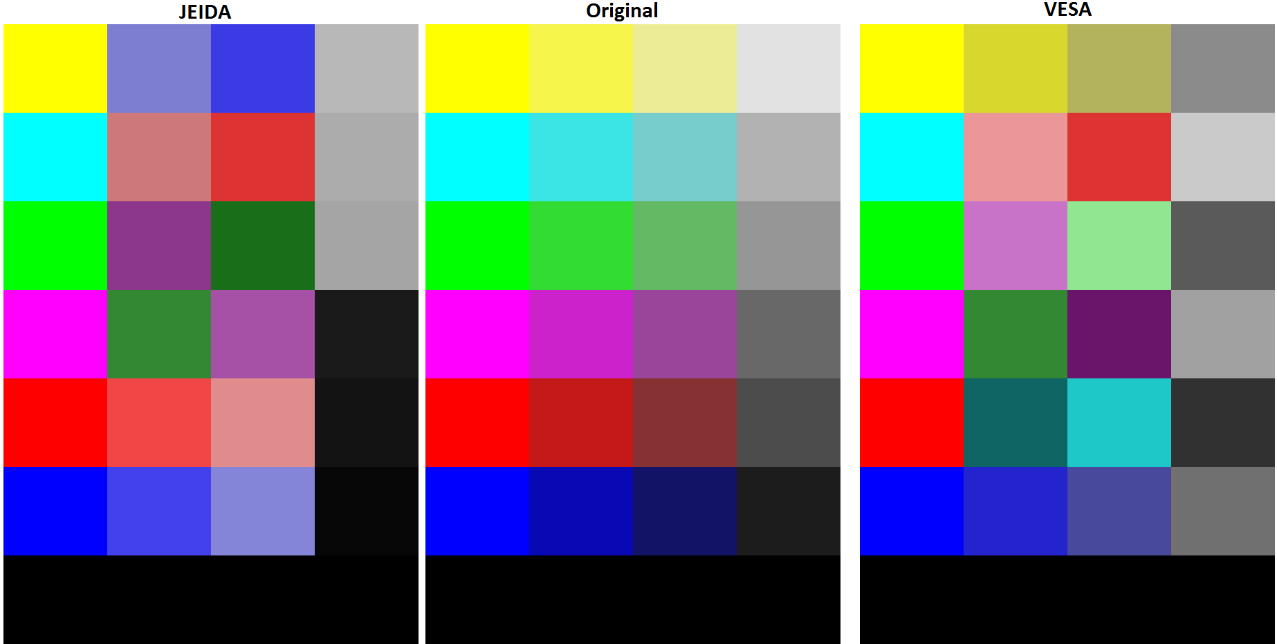
    The LG display allow to select the LVDS mapping between JEIDA and VESA. I encountered such issue again and images were generated to help diagnose the issue.

    The original image is pass through the conversion mapping to obtain the VESA and JEIDA images.

    Read more »

  • HDCP / HDMI Color Space

    Stanislas Bertrand08/19/2016 at 02:32 0 comments

    I got a Chromecast and I was disappointed when no image was displayed on screen. The Chromecast enables HDCP which the HDMI to LVDS controller doesn't support.

    I have bought a HDMI splitter in order to overcome the HDCP issue. The display has some issue with the splitter. The screen doesn't display an image when connected directly to the splitter. When doing Splitter -> Selector -> Screen the display show a image correctly from the computer but the image from the Chromecast has a purple tint. Some article on google talks about the hdmi color space being invalid 4:4:4 YCbCr vs 4:4:4 RGB.

    Test performed on the HDMI splitter :

    • 2ch audio : ok
    • DTS and AC3 : not supported but advertised. I tested with 2 systems, a regular HD-TV with AC3. AC3 is not available thru the splitter
    • performance : unit gets really warm. There is an LDO inside, terrible efficency. Consums 300mA.

    The unit doesn't take into account the screen configuration. I have a display that only support RGB 4:4:4. My computer displays fine but not the Chromecast.

    The issue would be more color space related than HDCP related. The Chomecast is able to display correctly on a HD-TV. The same HD-TV reports HDCP as not supported under the audio properties.

  • PIC16F1455 Programming

    Stanislas Bertrand08/09/2015 at 23:55 0 comments

    Before doing the programming of the onboard PIC microcontroller, I made a LaTeX documentation of my system so I can easily refer to it and update it as I code. I change some pin assignment due to the PIC IO limitation. The RA3 is an example, the pin is input only therefore I connected it to one of my push button. The USB PIC16F1455 Breakout Board was very useful to test and debug my programming prior flashing my TV.

    Schematic

    BreadBoard

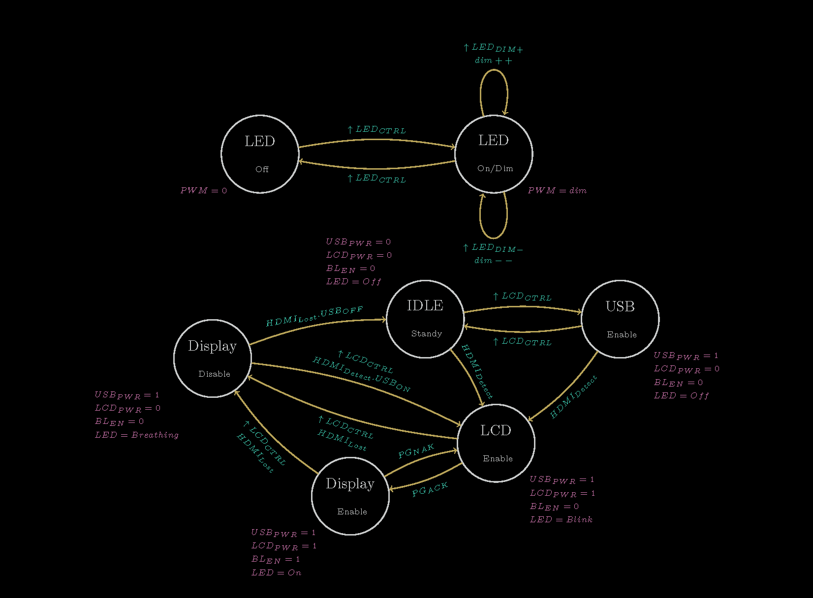
    System State Machine

    In order to perform tests during my development, I setup a test bench with my BusPirateV4. I wrote a BASIC script to easily generate my test signals. With my test system behaving as I wanted, I flashed the onboard PIC. The display can now be turned On/Off, put into standby. The control of the 5V USB power regulator allow to power up the Raspberry PI. The USB power regulator will be turn off when no signal is detected from the HDMI and the USB serial connection is not active. The USB serial connection allow to control the screen from a terminal. The USB and Display output can be over-written. The LED is also controlled and dim via the serial.

    10 PRINT "Setting IO ..."
    11 LET D=255
    13 PRINT "HDMI    <> MOSI"
    14 LET D=D&254
    15 PRINT "LCD PG  <> CLK"
    16 LET D=D&253
    17 PRINT "LCD PWR <> MISO"
    18 PRINT "USB PWR <> CS"
    19 PRINT "D=";
    20 PRINT D
    21 SEND D
    22 PSU 1
    23 PRINT "Done"
    
    30 PRINT "Menu :"
    31 PRINT "1-HDMI"
    32 PRINT "2-LCD PG"
    34 PRINT "3-END"
    35 PRINT "4-Loop Test"
    
    50 GOSUB 3000
    51 LET H=(R&1)
    52 LET P=(R&2)/2
    53 LET L=(R&4)/4
    54 LET U=(R&8)/8
    55 PRINT "HDMI    : ";H;" LCD PG  : ";P
    56 PRINT "LCD PWR : ";L;" USB PWR : ";U
    57 INPUT "Select",S
    58 IF S=1 THEN GOTO 200
    59 IF S=2 THEN GOTO 300
    61 IF S=3 THEN GOTO 1000
    62 IF S=4 THEN GOTO 400
    63 IF S=5 THEN GOTO 500
    64 GOTO 30
    
    200 PRINT "HDMI value"
    201 GOSUB 2000
    202 PRINT "HDMI Set to ";V
    203 LET V=V&1
    204 GOSUB 3000
    205 LET R=R&254
    206 LET R=R|V
    207 PRINT R
    208 SEND R
    209 GOTO 50
    
    300 PRINT "LCD PG value"
    301 GOSUB 2000
    302 PRINT "LCD PG Set to ";V
    303 LET V=V&1
    304 LET V=V*2
    305 GOSUB 3000
    306 LET R=R&253
    307 LET R=R|V
    308 PRINT R
    309 SEND R
    310 GOTO 50
    
    400 PRINT "Test PG"
    401	FOR B=1 TO 10
    402 LET M=253
    403 LET V=2
    404 GOSUB 4000
    405 PRINT B;"PG (1)"
    406 DELAY 5000
    407 LET M=253
    408 LET V=0
    409 GOSUB 4000
    410 PRINT B;"PG (0)"
    411 DELAY 2000
    412 NEXT B
    413 GOTO 50
    
    500 PRINT "Test HDMI"
    501	FOR B=1 TO 10
    502 LET M=254
    503 LET V=1
    504 GOSUB 4000
    505 PRINT B;"-HDMI (1)"
    506 DELAY 5000
    507 LET M=254
    508 LET V=0
    509 GOSUB 4000
    510 PRINT B;"-HDMI (0)"
    511 DELAY 2000
    512 NEXT B
    513 GOTO 50
    
    1000 PRINT "All Off & Input"
    1001 SEND 0
    1002 SEND 255
    1003 PSU 0
    1004 END
    
    2000 PRINT "1-ON"
    2001 PRINT "0-OFF"
    2002 INPUT "Value",V
    2003 RETURN
    
    3000 LET R=RECEIVE
    3001 PRINT "R : ";R
    3002 RETURN
    
    4000 LET R=RECEIVE
    4001 LET R=R&M
    4002 LET R=R|V
    4003 SEND R
    4004 RETURN

  • Finishing Display

    Stanislas Bertrand04/12/2015 at 04:26 0 comments

    From the first work some improvements could be made and other had to be done.

    The cabling had to be redone so the screen could be usable and easy to handle. I found a nice aluminum box on mini-box.com the case1c1. That box is cheap and has correct size. What's going in the box :

    I added another 5V Step down power supply for another pair of USB output. The goal is to control those USB to turn on or off the RasPI or other devices such as USB Powered Speaker.

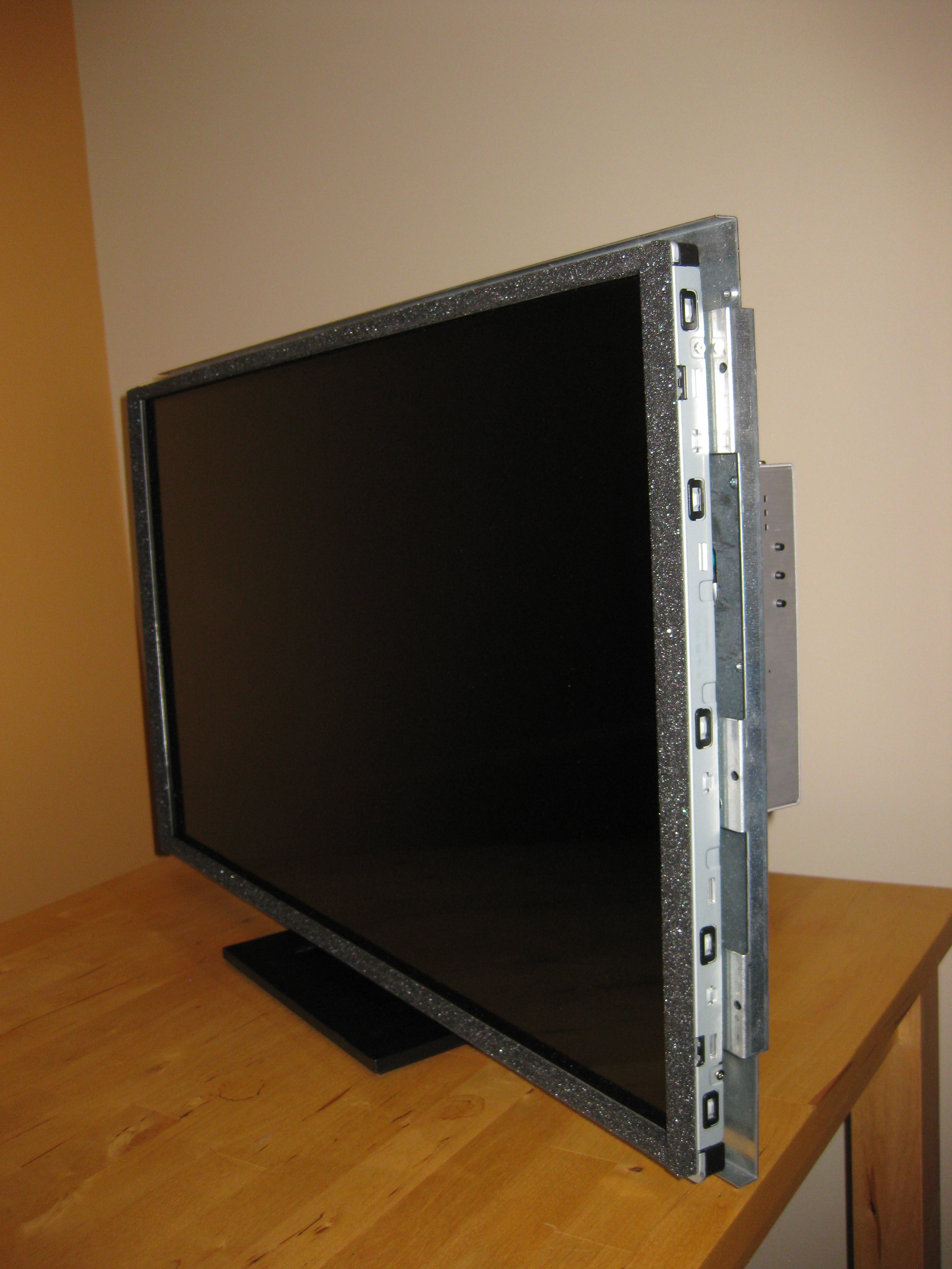
    The display is supported by a DELL stand. It works quite nicely, the screen is able to tilt back and forth.

    The power supply is mounted on the back panel, just need a power cord and an HDMI to enjoy a movie.

    The push buttons are not yet active, the PIC16F1455 needs to be reprogrammed to handle them. The PIC16F1455 will also act as a Virtual Com Port to control the screen via USB.

    Box wiring

    Back Panel

    Display and side control

View all 4 project logs

Enjoy this project?

Share

Discussions

user1969903 wrote 02/16/2023 at 11:47 point

I'm trying to use the same hdmi to lvds converter as you've used for this project but I only get a black screen. I don't think it's an HDCP issue in my case. Do you happen to have any troubleshooting steps or hints or something to at least help me get anything on the screen even if it's just a garbled up image?

  Are you sure? yes | no

marek wrote 11/09/2018 at 16:15 point

Hello. I am doing also on HDMI to dual LVDS converter and I have a problem with screen, converter si made with the same chips as yours and my screen look like yours. It looks like columns are shifted, I cant read text on the display. What did you changed?

  Are you sure? yes | no

Stanislas Bertrand wrote 08/10/2016 at 02:10 point

I got a Chromecast and I was disappointed when no image was displayed on screen.

The Chromecast enables HDCP which the HDMI to LVDS controller doesn't support.

  Are you sure? yes | no

Stanislas Bertrand wrote 03/13/2017 at 04:52 point

In fact it is a color space issue not HDCP. The controller only handles RGB not YCbr. But most likely HDCP will be an issue later on.

  Are you sure? yes | no

Similar Projects

Does this project spark your interest?

Become a member to follow this project and never miss any updates