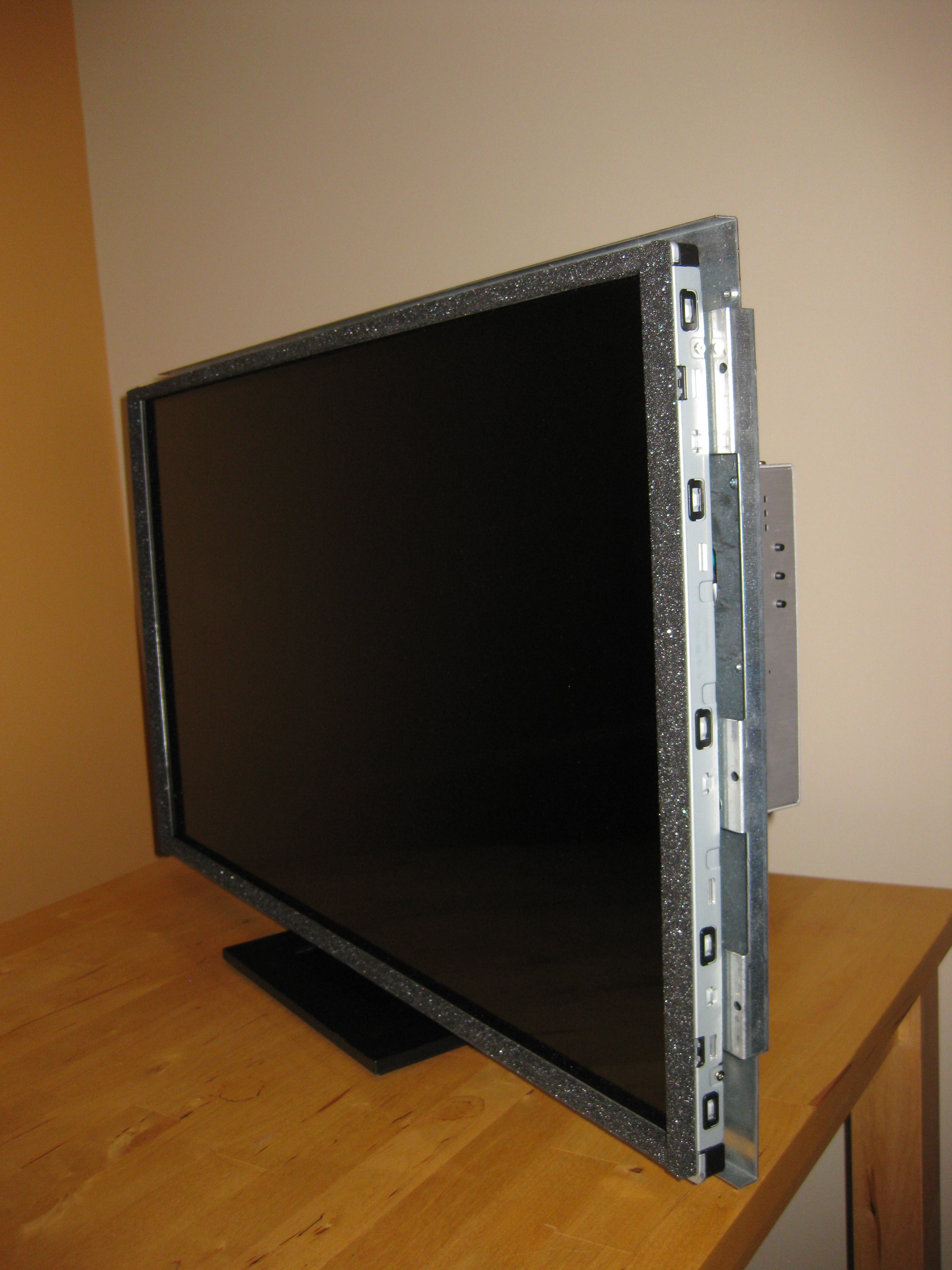
The display is not connect to anything, it has only the LDC Controller and the Back-light Controller.
Doing some search on Google, I found the LG LD320EUN datasheet which is a must have. I would have had a lot of difficulties without proper documentation. The display interface is dual channel LVDS. There is some option to connect to such interface, either a manufacturer boards like the Nitrogen6_MAX or a HDMI converter. There is not a lot of boards with dual channel LVDS output and they are not cheap. Since I had no clue if the display was even functional, I didn't want to invest to much in it. The cheaper and more flexible alternative is a HDMI converter. Ebay has a lot of LCD Driver Adapter Board but support and documentation is little. I selected the HDMI to dualLVDS converter. chalk-elec.com has documentation about their product and good support and how-to guides.
First things first, I tested the display to see if anythings was alive in the LCD Driver board or Back-light Controller. I should have tested the display before ordering anything but we get carried away sometimes. The Back-light doesn't work by itself as the back-light PWMs are controlled by the LCD Driver board. When both are powered, the back-light lights up. Since the display just need some signal, the next thing is the LVDS connector.
The LVDS connector on the cable of the LCD Driver is a 30-pin connector ( 2 Row x 15 pin ). BTW, If anyone knows the type of connector that is, I would like to know. I wish I knew to what board it was connected before, it could have gave me a clue about things. The tricky part is the dual channel LVDS matching, the LD320 datasheet has the LVDS signal described as follow : First Data Pixel 0,0 Pixel 2,0 and Second Data Pixel 0,0 Pixel 2,0 therefore I assign First LVDS channel to Even pixel and Second LVDS channel to Odd Pixel. The datasheet also describe the LVDS Clock to Clock Skew (Even to Odd) which collaborate the assumption. I planned to crimp connectors the LVDS cables but the old connector pin match the new one, that make it easier. The result of the cabling is the picture with Mordor like writing. The good thing is that pixels are being displayed on the screen. The disappointment is that odd and even pixel of each line are interverted.
I carefully reviewed the documentation and thing seems to be in order. How come pixels are not in the right order ? The answer I could come up with is that the DS90C387A datasheet use pixel numbering from 1 and the display datasheet count pixels from 0. Anyway I had to undo the connector I just did without breaking the plastic tab latching the connector in the housing (Messed up 2 out of 20, not too badly thought !). With LVDS channels matching, raspberrypi pi login displays clearly :).
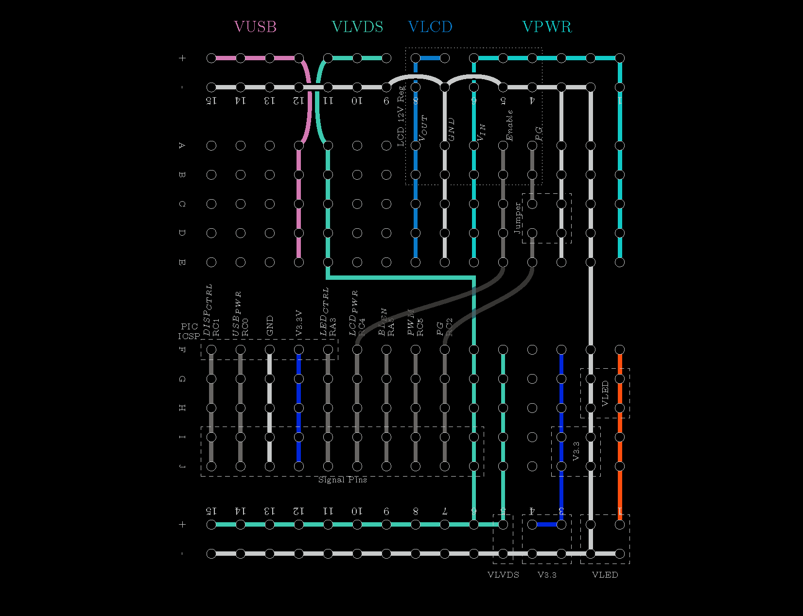
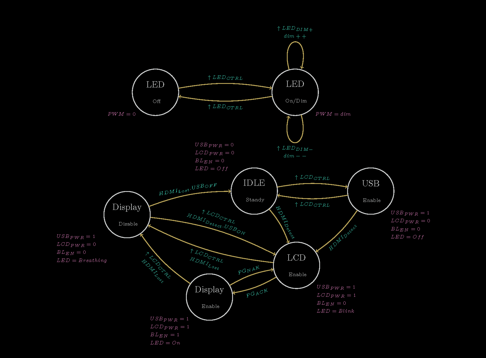
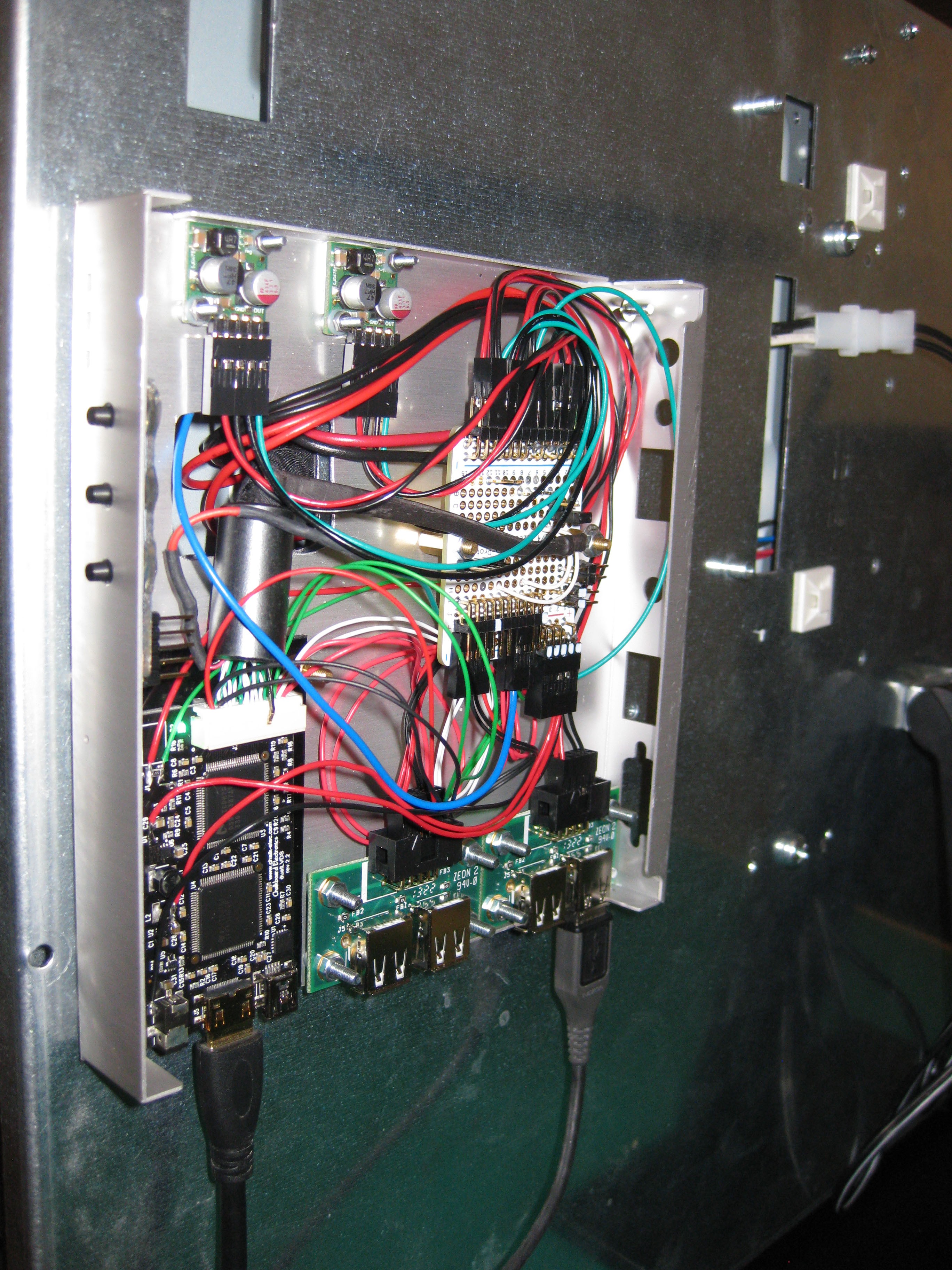
With the display working correctly, the cabling could be done correctly. The HDMI to dualLVDS converter has a PIC16F1455 micro-controller integrated. It enabled the converter outputs when HDMI signal is present. The goal is to have the back-light controller ON/OFF pin controlled by the micro-controller so when the HDMI is disconnected the display turns off. I'm using a breadboard PCB to connect the signal of the HDMI converter to the screen signal. Space is left on the breadboard for improvements :
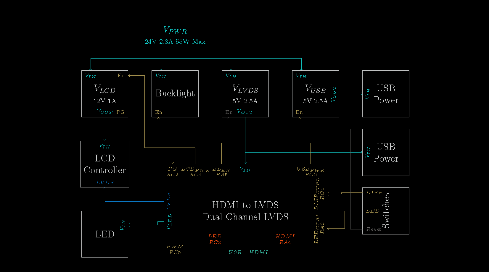
- The display is currently powered by a 24V power supply. There is a 24V to 12V DC-DC converter rated at 120W. I'm not going to use 10A @ 12V for the LCD Controller. I'll change that for a smaller buck converter matching the LCD Controller power requirements.
- LCD Controller should be enabled only when HDMI signal is present, that will reduce power consumption in sleep mode.
- The HDMI Converter is using an external 5V power supply. Add a 5V buck converter to power the adapter. That power supply could also power the Raspberry Pi either via the PIC16F1455 USB or a direct line.
- On the HDMI to dualLVDS converter there is a back-light boost converter. It is not suited for such a display but I could drive a LED strip and make TV Dynamic...
 Stanislas Bertrand


I'm trying to use the same hdmi to lvds converter as you've used for this project but I only get a black screen. I don't think it's an HDCP issue in my case. Do you happen to have any troubleshooting steps or hints or something to at least help me get anything on the screen even if it's just a garbled up image?