-
USB 2-0 Type-C breakout
12/12/2022 at 16:16 • 0 commentsFiles on GitHub.
I wanted to run a test for some USB 2.0 type-C connectors I got off Amazon and figured why not make it into one of the widgets.
It is inspired by the Adafruit USB-C breakout but I wanted to keep the connector to the breadboard power rails and added a power indicator LED.
I liked how the Adafruit breakout has the pull-down resistors on CC1 and CC2 on board, so you don't have to add them every time, but of course you can just leave them unpopulated.

The board is requesting power from a USB PD power supply and injects it into the breadboard power rails I ordered the boards from Aisler and if you are interested, I have shared them via this link. I have also been thinking about sharing the other boards individually on Aisler and OSHpark, so let me know if that's something you're interested in.
-
@SUFs boost regulator
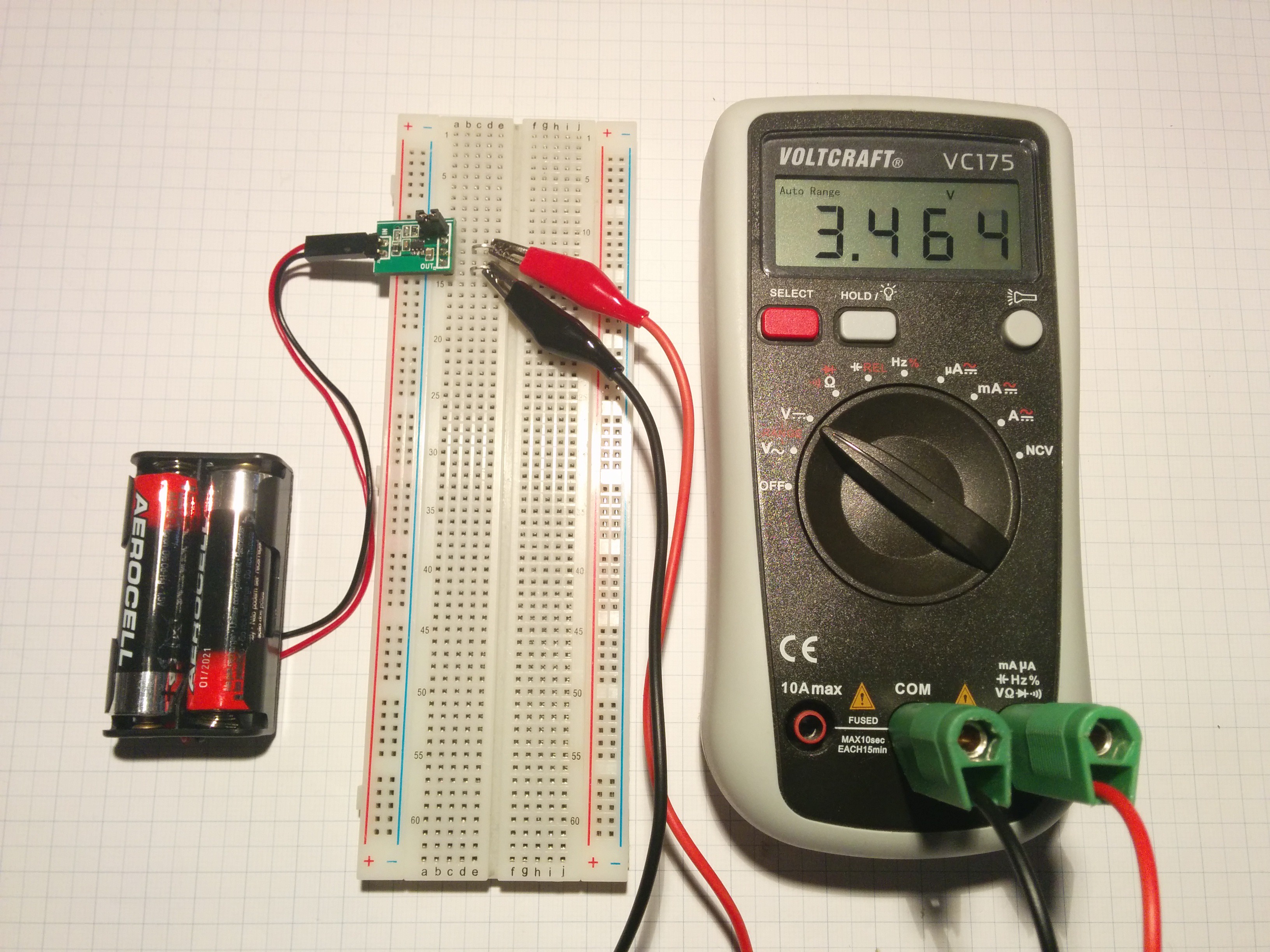
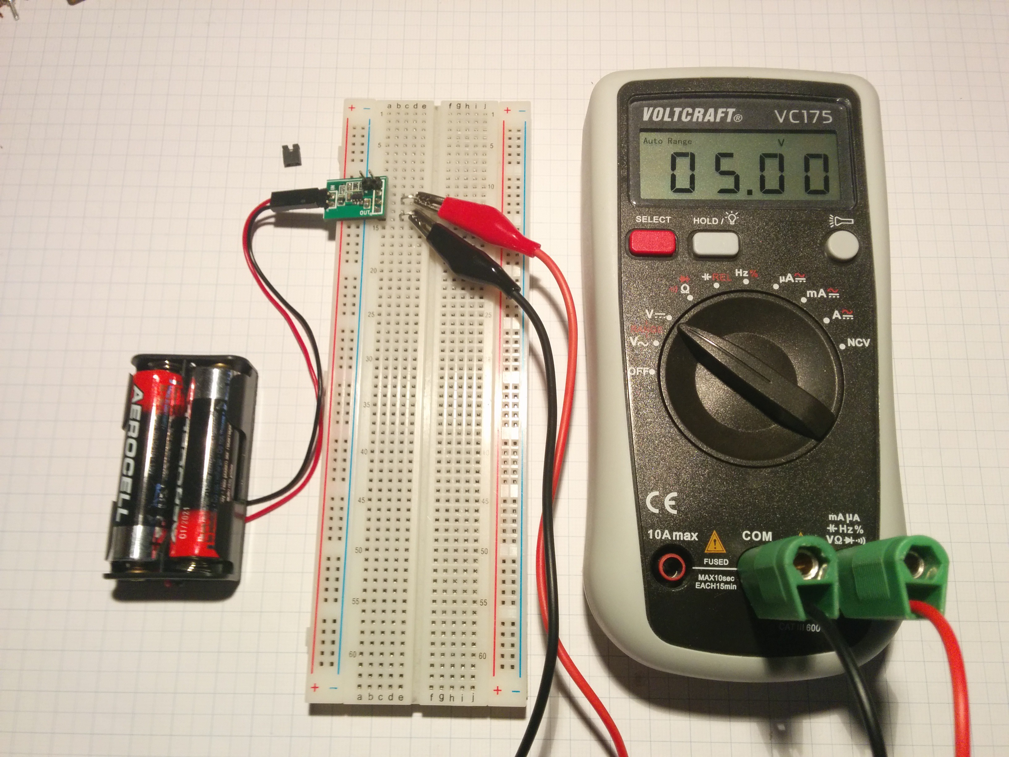
07/31/2016 at 15:23 • 0 comments@SUF kindly supplied me with another one of his very useful widgets. This time it's a breakout for the MCP16252 boost regulator that can be configured to output either 3.3V or 5V by setting or removing a jumper respectively:
SUFs original post about the board can be found here which also shows the original design. My EAGLE remake can be found in the GitHub repo as usual.
As you may expect I completely obsessed over making my redesign of the board even more breadboard compatible than it needed to be up to the point of it being not very practical. Initially I wanted the board to be able to supply power
- to the power rails from the battery pack,
- to the rails from a source inside of the breadboard and
- to the inside of the breadboard from the power rails.
After not making any significant progress with this idea (and taking way too much time) I decided to step back and and share the board in its current form:
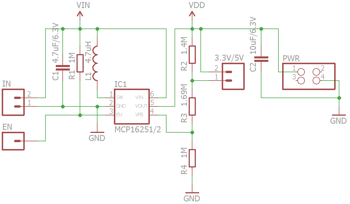
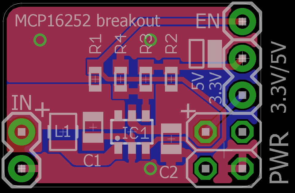
The schematic is pretty much identical to SUFs version while the layout has been slightly altered to allow the power pins to be plugged into the power rails and the enable pin to be plugged into the inside of a breadboard. I tried to keep as true as possible to the reference design and keep it on a single layer.
Many thanks to @SUF for all his contributions to the project and my apologies for taking so long with this write-up ;)
-
UART matrix
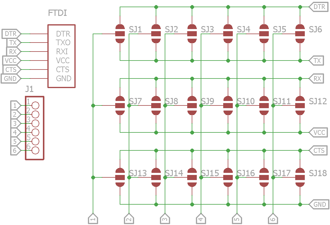
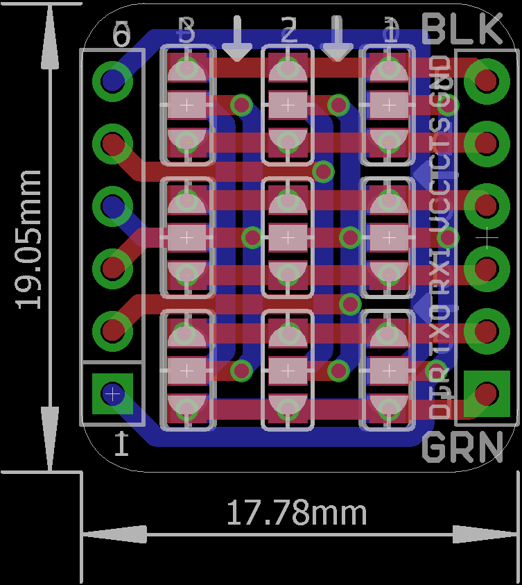
01/24/2016 at 20:43 • 0 commentsTLDNR: See schematics and board below or on GitHub.
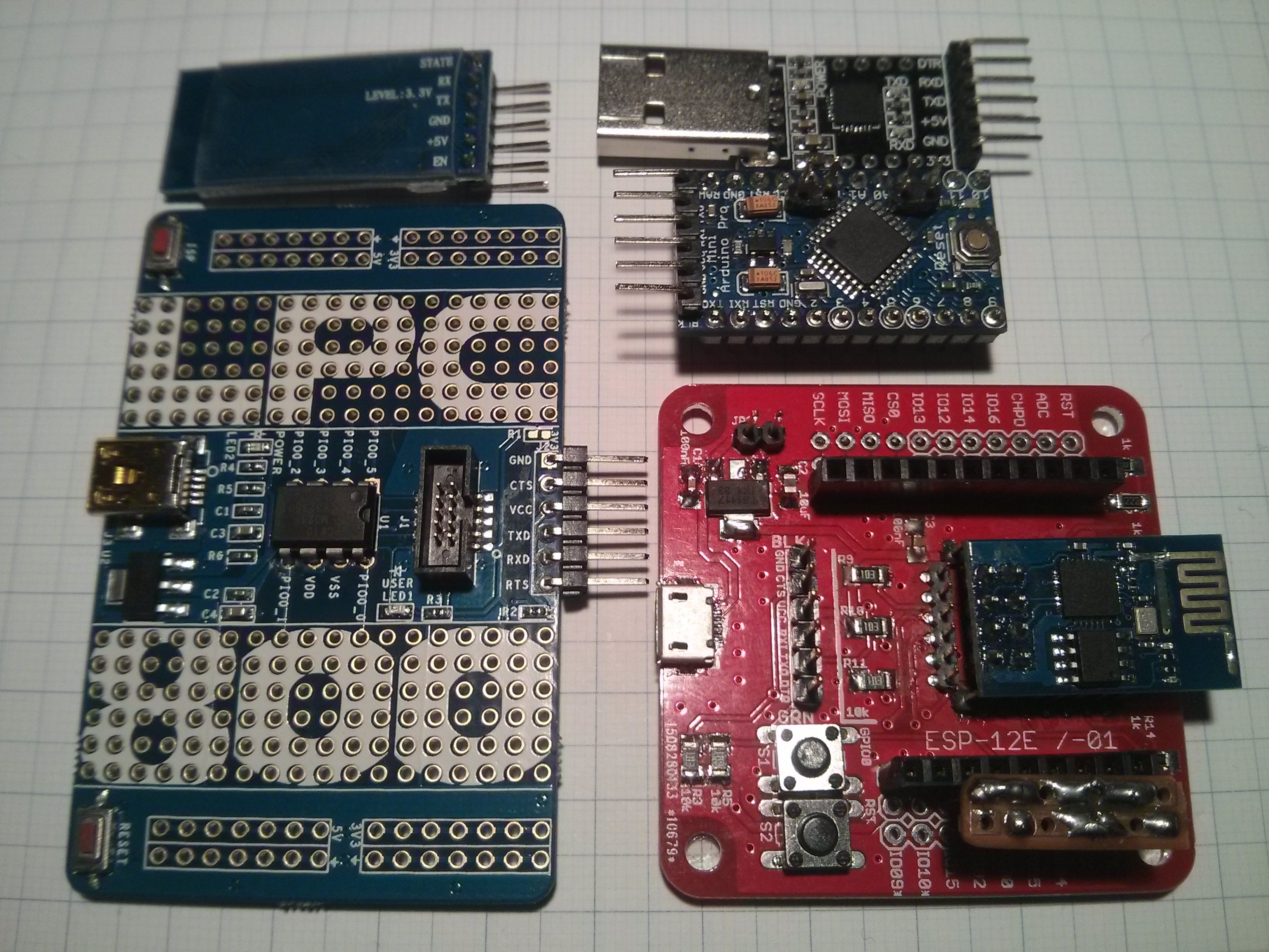
I often end up making custom cables to connect various devboards like the #Ignore this ESP8266 board, an Arduino Pro Mini or a HC-05 bluetooth module to my CP2102 USB serial converters. Ok, the Pro Mini is actually 1-to-1 compatible but the point is that they all have a different pinouts.
It's not that big of a deal with cables like these but it made me think that a small adapter board might be useful. Designing such a board for each of the above doesn't really solve the problem so I need one board that can be made to fit all:
I guess by now it's pretty clear how I arrived at the name but of course the board is not limited to UART but can also be used to fan-out (or -in) other signals like an I²C bus or distributing power.
-
1-5x SMD LED breakout
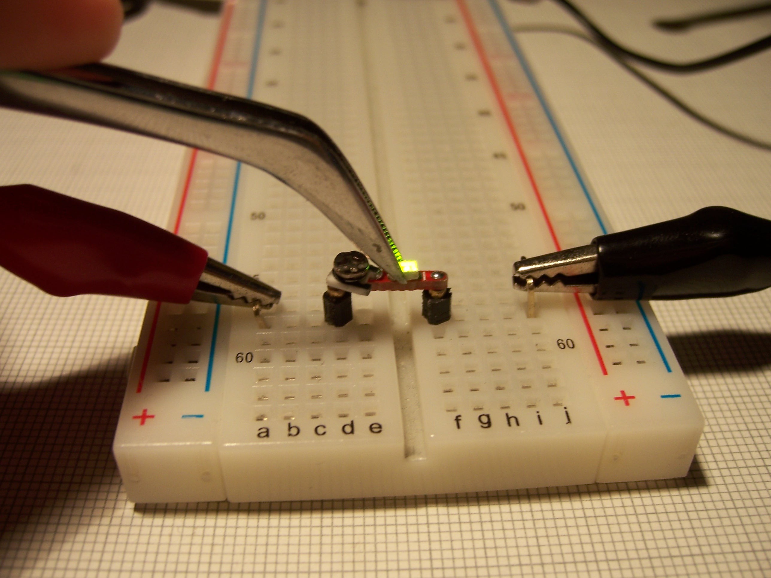
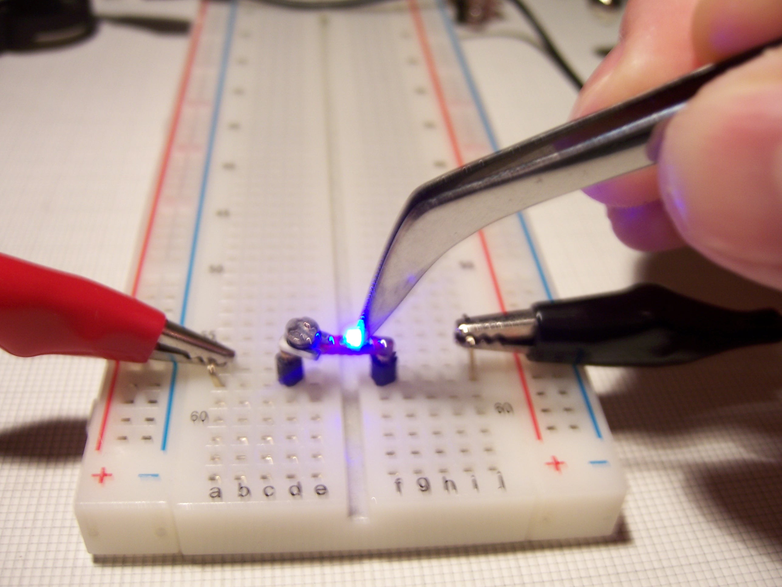
11/05/2015 at 13:44 • 2 commentsI haven't written about this one before because I think it's pretty trivial and self explanatory but for completeness here's the link to the GitHub repo. On a side note I'd like to mention that I chose the number of LEDs to be 5 because that's the max you can fit side-by-side in the rail of a breadboard but obviously you can just use another one of these to make up a whole byte.
Another reason for this log is that I wanted to share some use cases for this board.
The first one is pretty obvious. Just don't solder the LED and you have yourself a SMD LED tester (optionally add a small potentiometer for good measure):
The problem with this is that you have to hook it up every time you need it so this is the next iteration of this idea:
 Just solder two of them to a CR2032 holder and that's pretty much it.
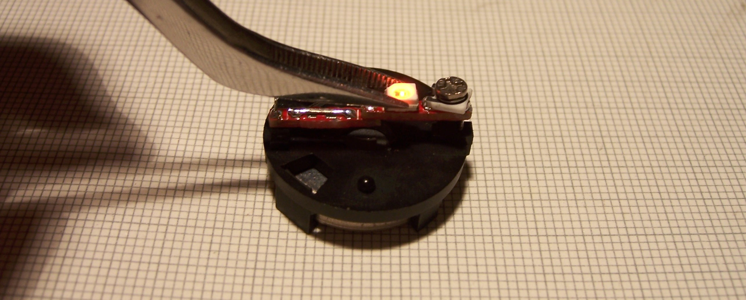
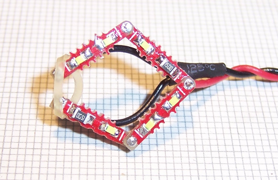
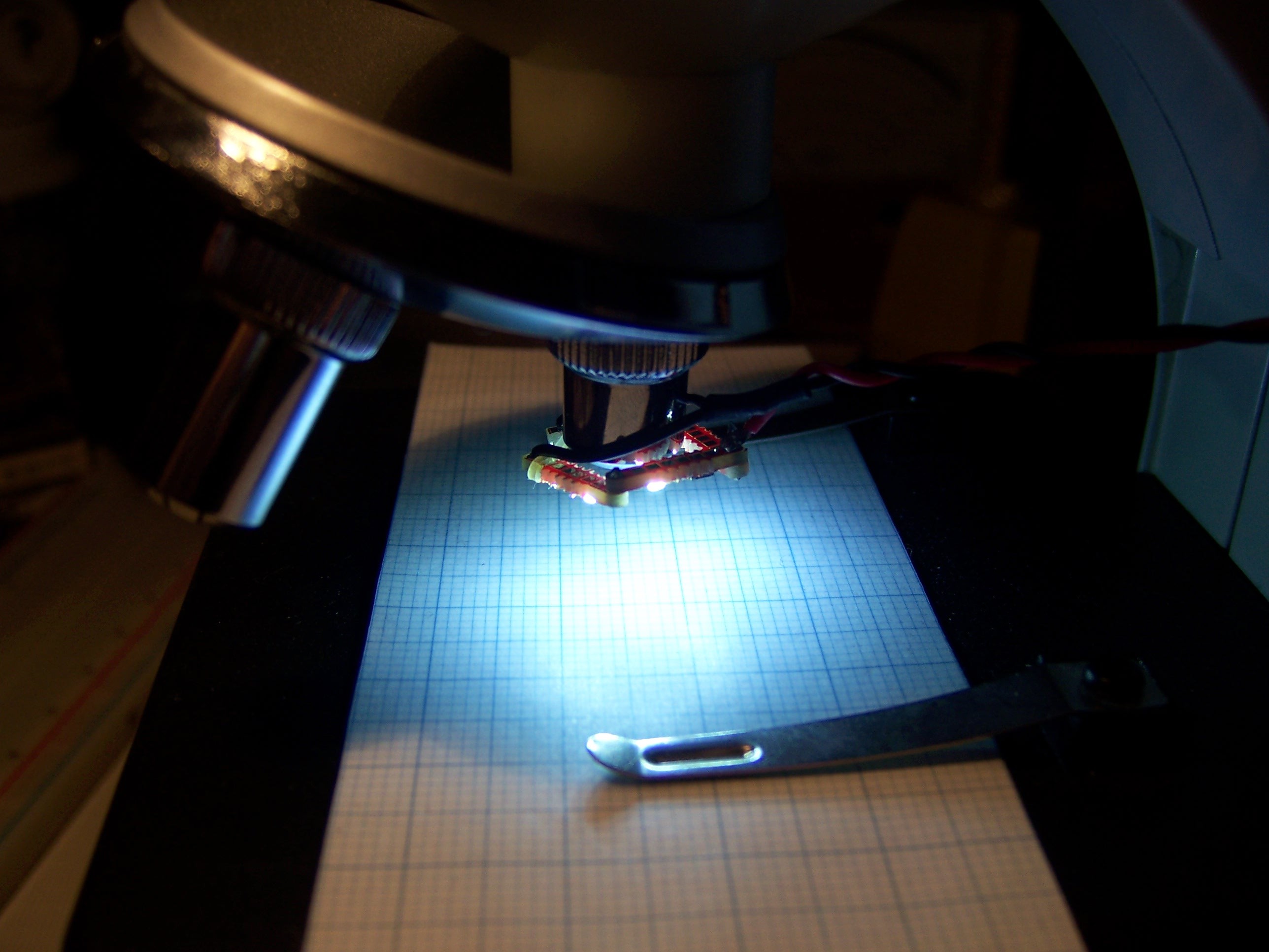
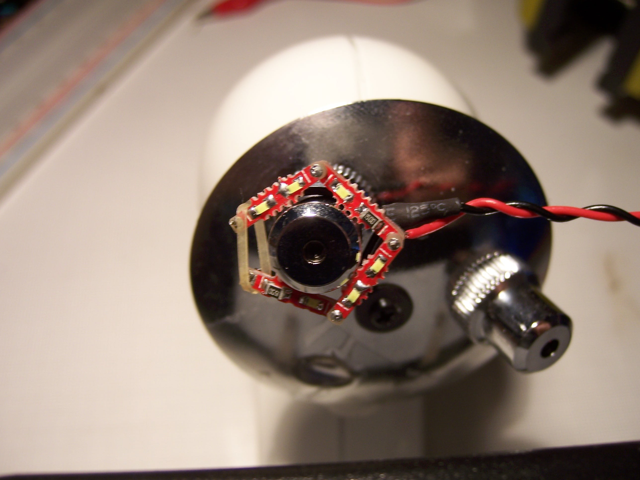
This next use case is for another project of mine where I tried to convert one of those cheap microscopes to be used for PCB inspection and maybe soldering:
The middle joint (on the right, where the supply voltage is attached) is actually not completely soldered such that the two rigid pieces form a clamp (or clamp-like device) that can be attached to an objective lens. -
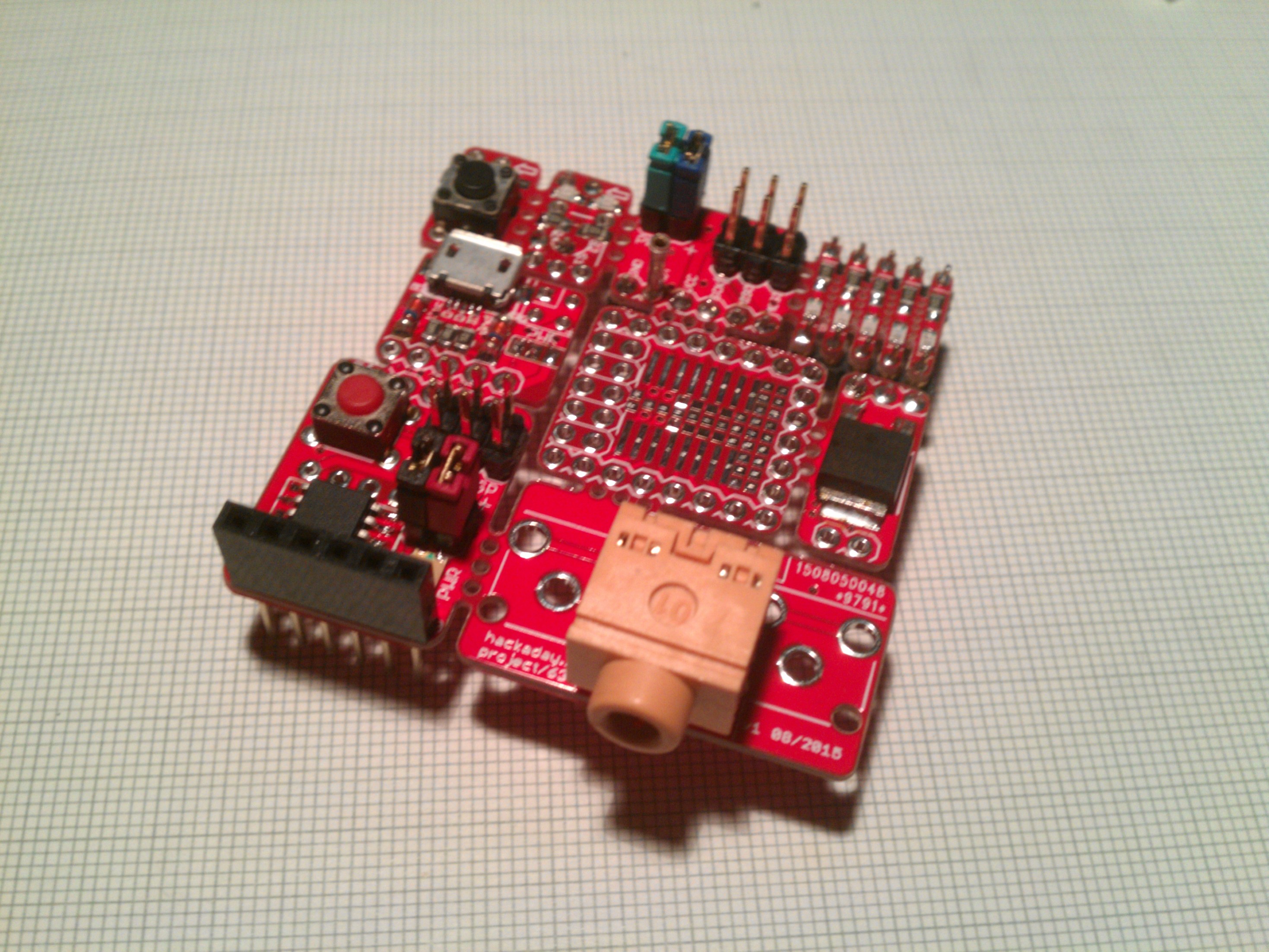
SMD breakout & proto board
10/18/2015 at 23:20 • 0 commentsThis one went from the simplest SOIC-16 breakout to a way over-designed board that will hopefully serve all* my SMD prototyping needs. I uploaded a couple of versions to the GitHub repo but the ones shown above are the only ones I had made so far.
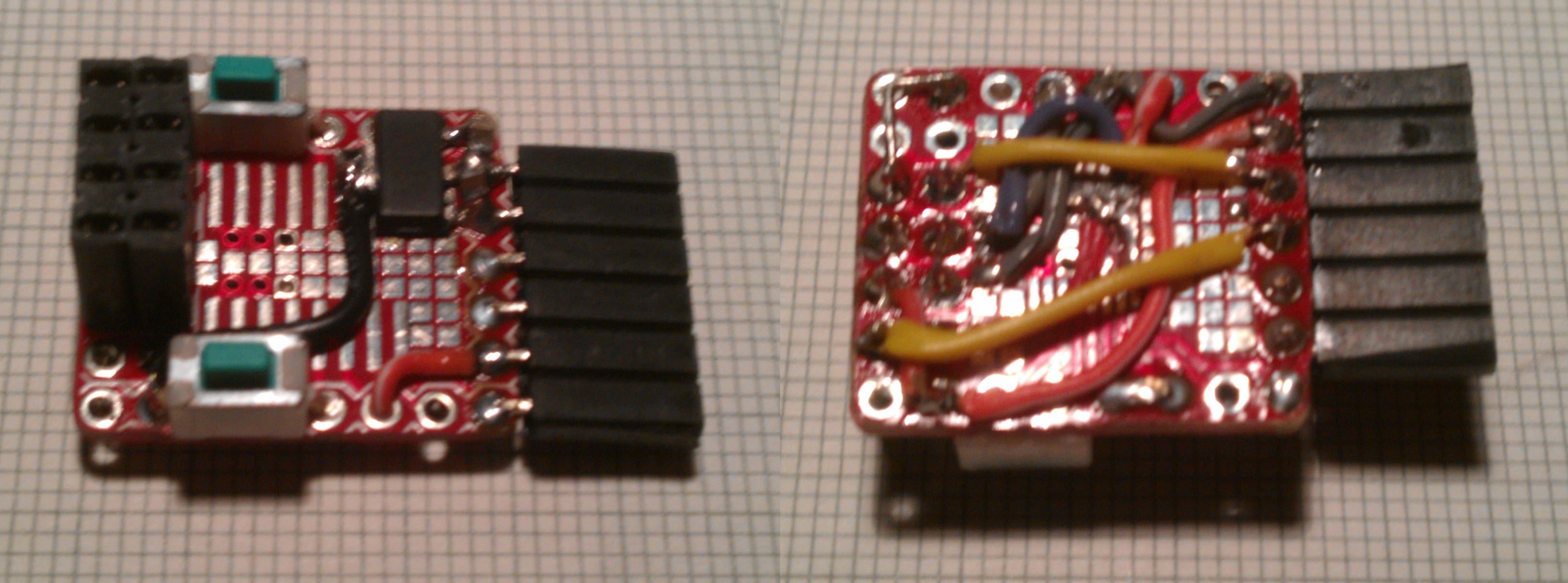
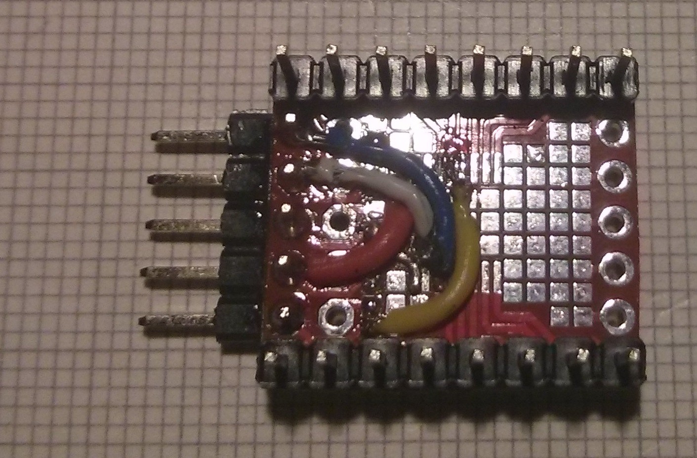
Basically it's a SOIC and TSSOP 16 breakout but I couldn't bare all the empty space so naturally I filled it up with SMD pads and additional headers. The idea was to also be able to use it to make various adapters like this:
I'm planning on using this board to make another ESP-01 adapter, this time with a CH340. One could mount a USB-A plug to the 5x1 header footprint on one of the short sides but since I like µUSB so much I think I'll use my µUSB breakout instead. (It's not really recognizable in the second image but I substituted the USB-A plug of the USB to UART converter with one of those µUSB boards so it's pretty much the same concept.)
*at least some
Update 2016-01-20:
Just another quick example of a use for this board where the additional headers come in handy:
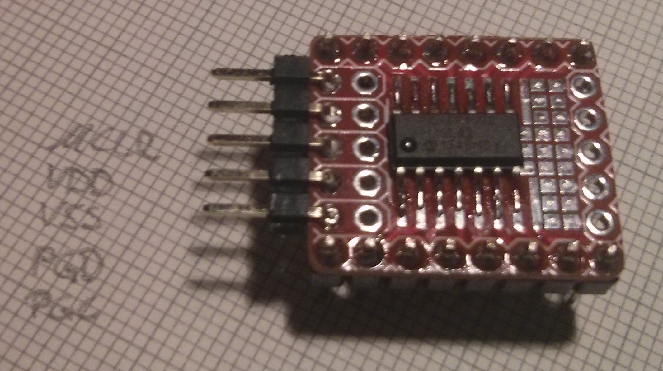
Basically it's just a breakout for a PIC16F1503 with some of the pins connected to an ICSP header. It's not shown in the 2nd image but I later added a pull-up on !MCLR and a capacitor on Vdd. There's some more space for a power LED, a LED connected to one of the pins and/or an external crystal. See also this log for the 'project' I used it for.
-
DB-x breakout
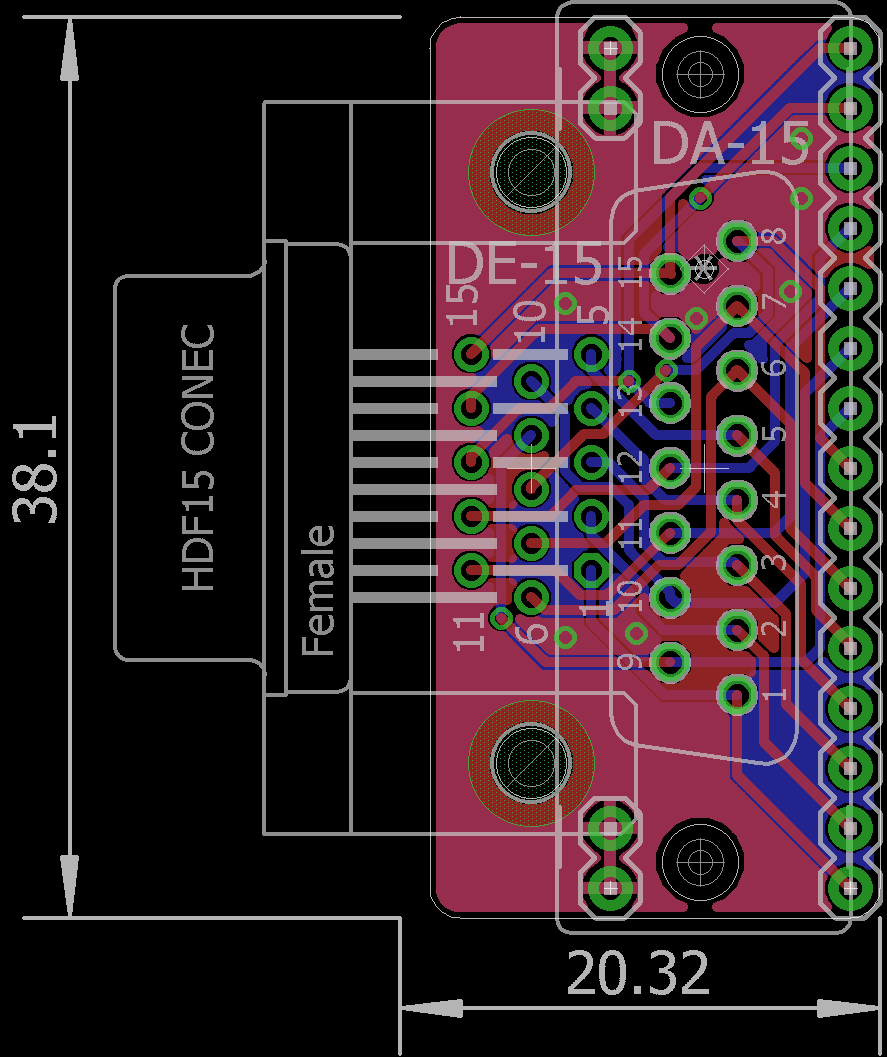
10/12/2015 at 18:33 • 0 commentsAs per @Howard Jones' suggestion I've made a breakout board for the following D-sub connectors:
- DA-15
- DB-9 (or more accurately DE-9)
- DE-15 (VGA)
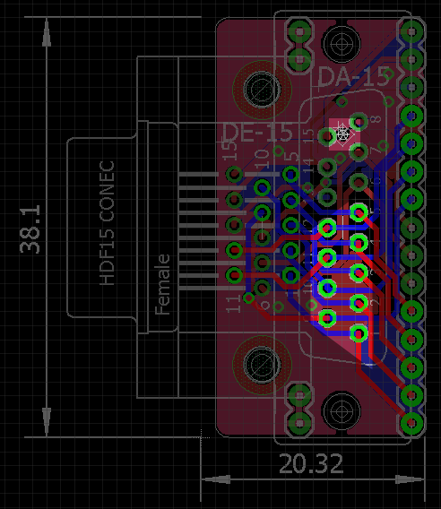
I'll spare you the (obvious) schematics (<- GitHub) but here's the board:

From the original version I switched to a slightly different DE-15 footprint whose rows of pins are a little further apart which seems more common. I also added two 2x1 headers to connect to the GND rail of a breadboard int order to ground the shielding and to better fasten the board.
I mentioned that I used the DA-15 footprint simply because there are already 15 pins on the board and it has the same spacing as a DE-9 so why not (even if it requires some modification). To use a DE-9 connector I thought one would use the lower nine pins and make a new mounting hole like this:
The upper highlighted area is where the connector's other shield connection/mounting point would be. There's already a small hole there so in order to attach the connector you can extend the hole to the required size without damaging relevant traces.
-
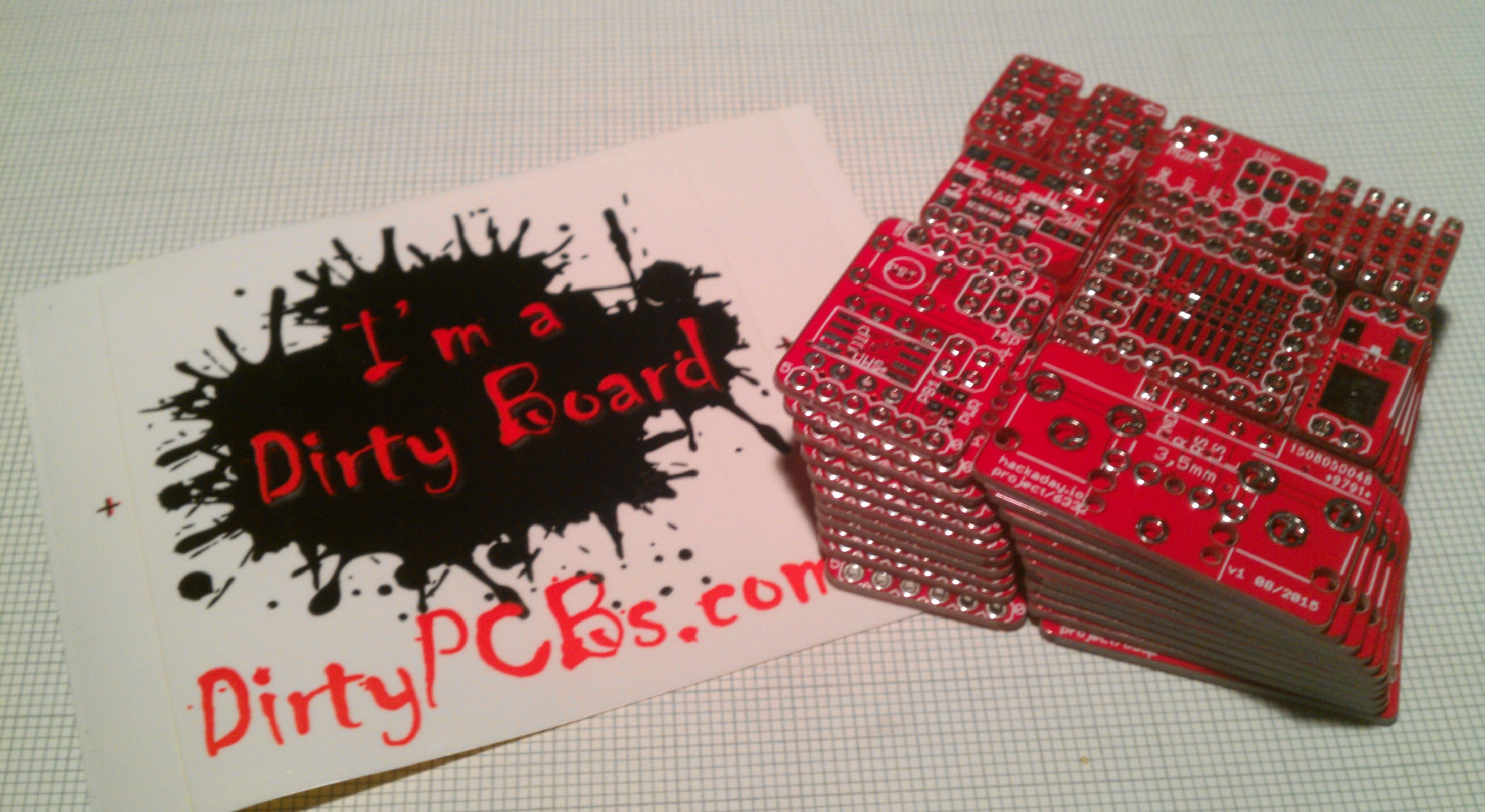
PCBs are in
10/01/2015 at 13:12 • 1 commentFinally!
A more or less completely soldered panel:
Pretty much upon unpacking them I found an error on the silkscreen of the uUSB breakout that must have occurred when I was panelizing the different boards. The order of the pins is wrong on the top silkscreen, where it's hard to read anyway, but it's correct on the bottom. The individual board file in the repo wasn't affected by this error.
So if you don't mind that mistake you can get one in the DirtyPCBs store or trade with me.
-
@SUFs negative voltage converter
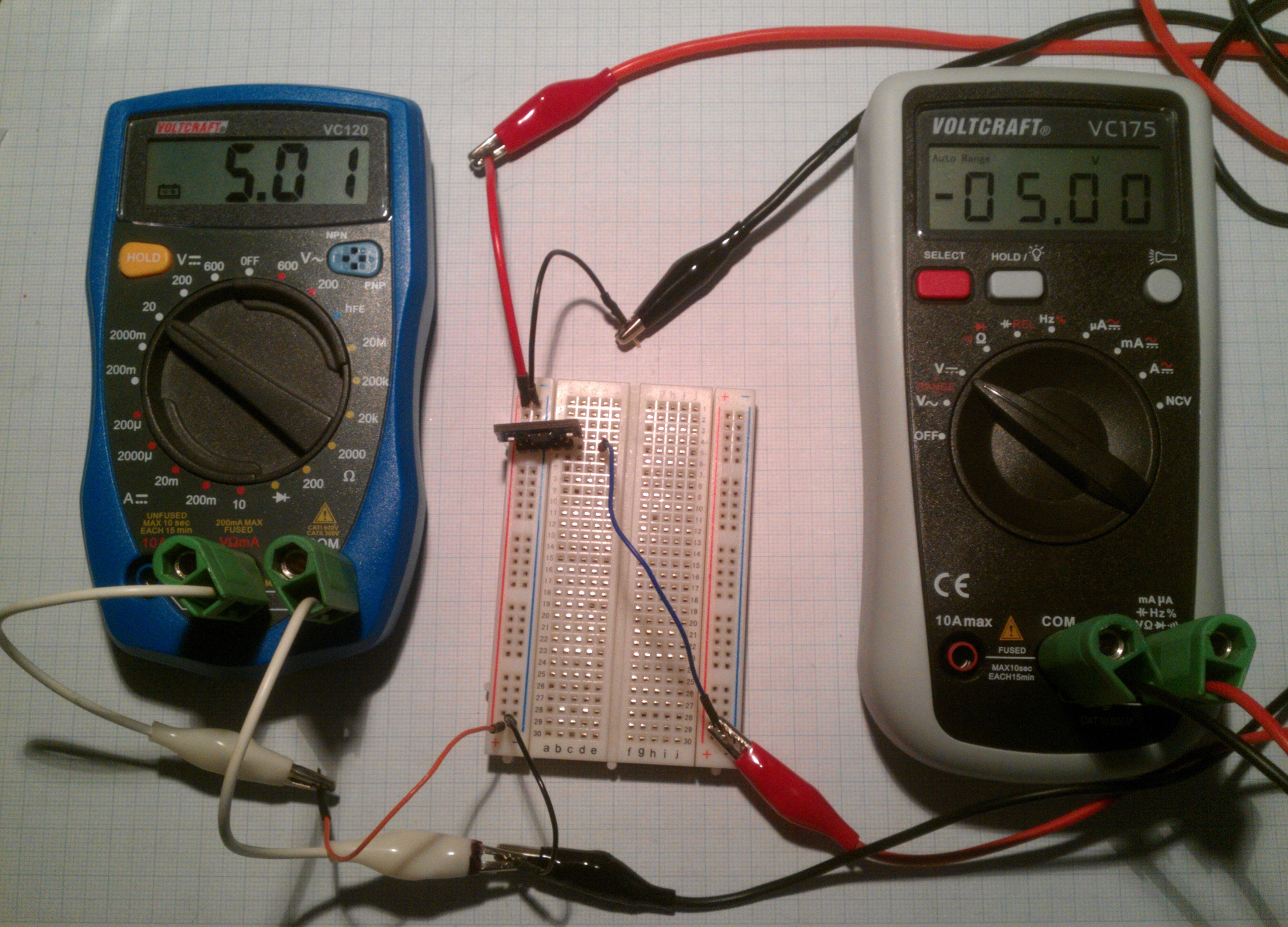
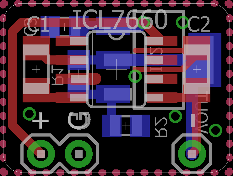
08/04/2015 at 16:15 • 4 commentsThis is another one of @SUFs contributions, the original files of which can be found here. It's a negative voltage converter based on the Intersil ICL7660S and works quite well as you can see:
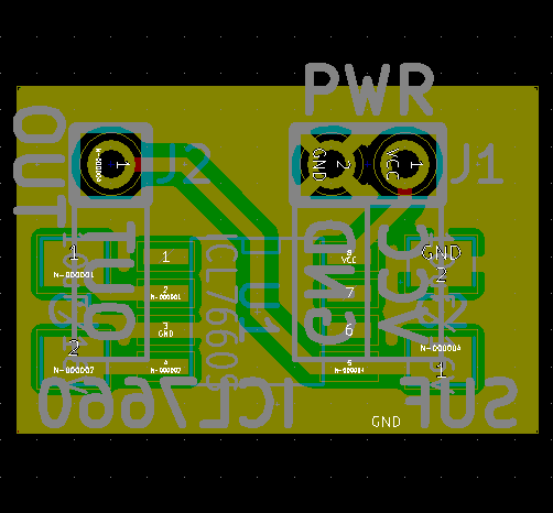
Here are the original schematic and board layout:
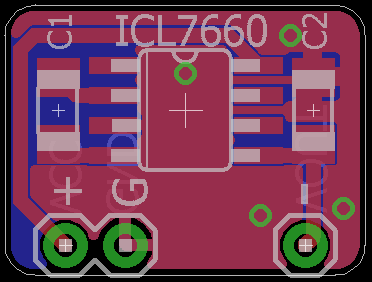
Since I mainly use Eagle, I remade it trying to stay as true to the original as possible.
However, since I wanted to make it as compact as possible (reducing the 'overhang' on the side of the pin headers) I ran into the problem of all the GNDs not connecting which required a slight rerouting to keep everything on one layer which is an advantage if you would like to etch it yourself (the GND vias are only redundancy).
... I can already feel the onset of feature creep caused by the empty bottom layer...
Update 2016-01-05:
I'm putting together another panel and wanted to include this board but since I'm not going to need ten of these I put a LD/LM1117 footprint on the back.
The board has footprints for resistors to adjust the voltage but if you use a fixed voltage device you can just short R2 to connect Adj to GND.
-
MOSFET breakout for PWM driver
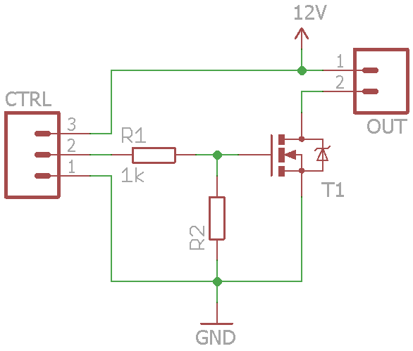
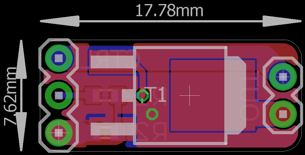
07/29/2015 at 17:42 • 5 commentsI was thinking about what else to put on the panel but couldn't come up with something original. Since the most essential parts for a 'starter kit' (buttons, LEDs) are already there I was thinking what the next step would be. In most tutorials[1] this next step is controlling something that requires more voltage or current than the MCU can deliver (besides using some special IC or a display). For this reason and because I need a PWM driver for other projects I threw together this MOSFET breakout:
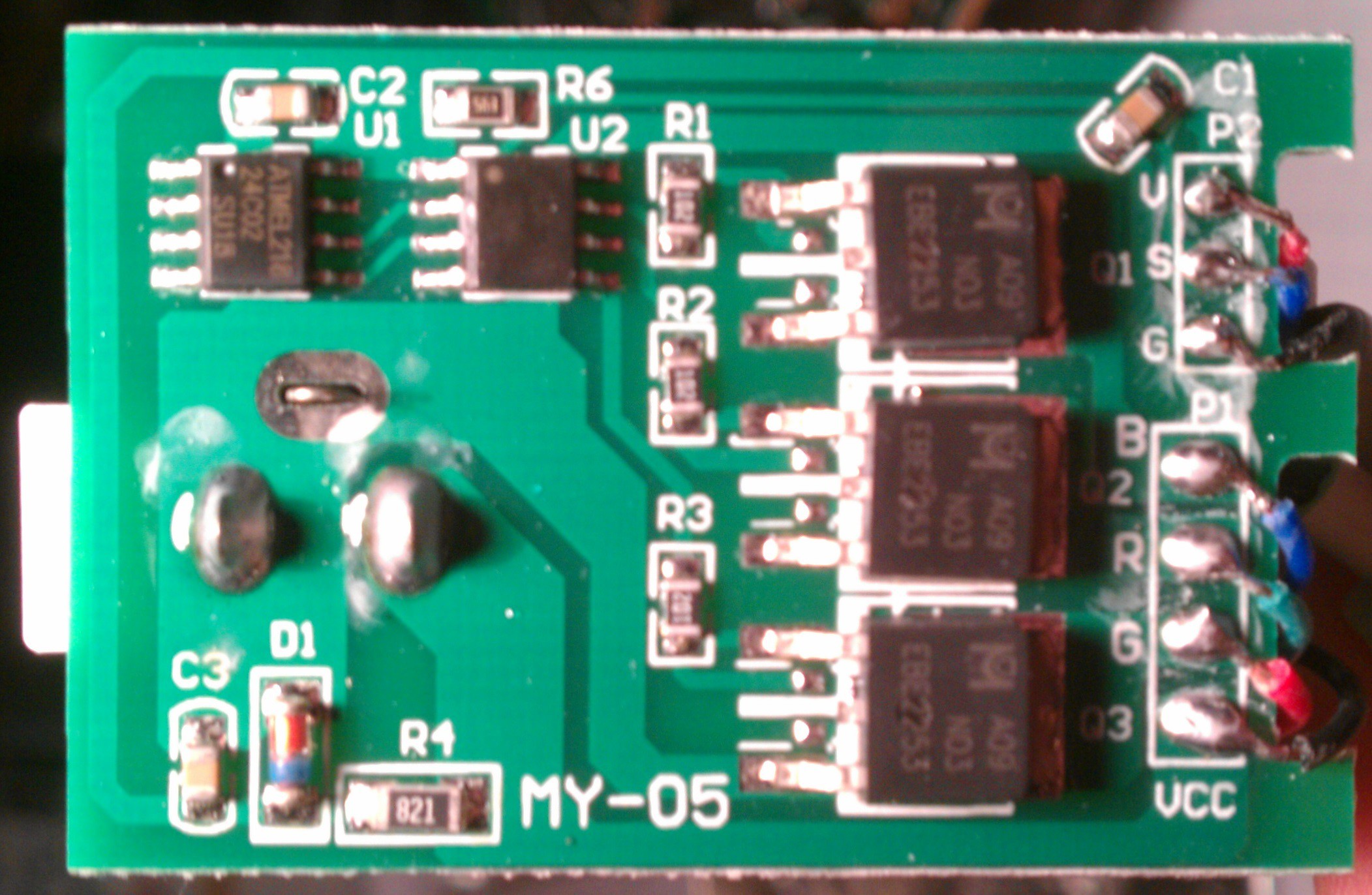
My sources for the schematic don't agree on one correct version for a MOSFET based driver and this cheap RGB LED driver that came with a LED strip even does something in-between:
Therefore I added the footprints anyway and will populate them as needed. I don't see why a MOSFET would require a voltage divider or a series resistor at the gate, but I'd be happy if anyone could let me know the reasoning behind that.
The pinout seems to be pretty common and since pin 2 and the tab are internally connected in a lot of cases[1] this board should also work with SOT-223 packages and as a general breakout thereof.
[1] citation needed
-
@SUFs USB-B breakout
07/16/2015 at 17:45 • 1 commentHere's another contribution from @SUF:
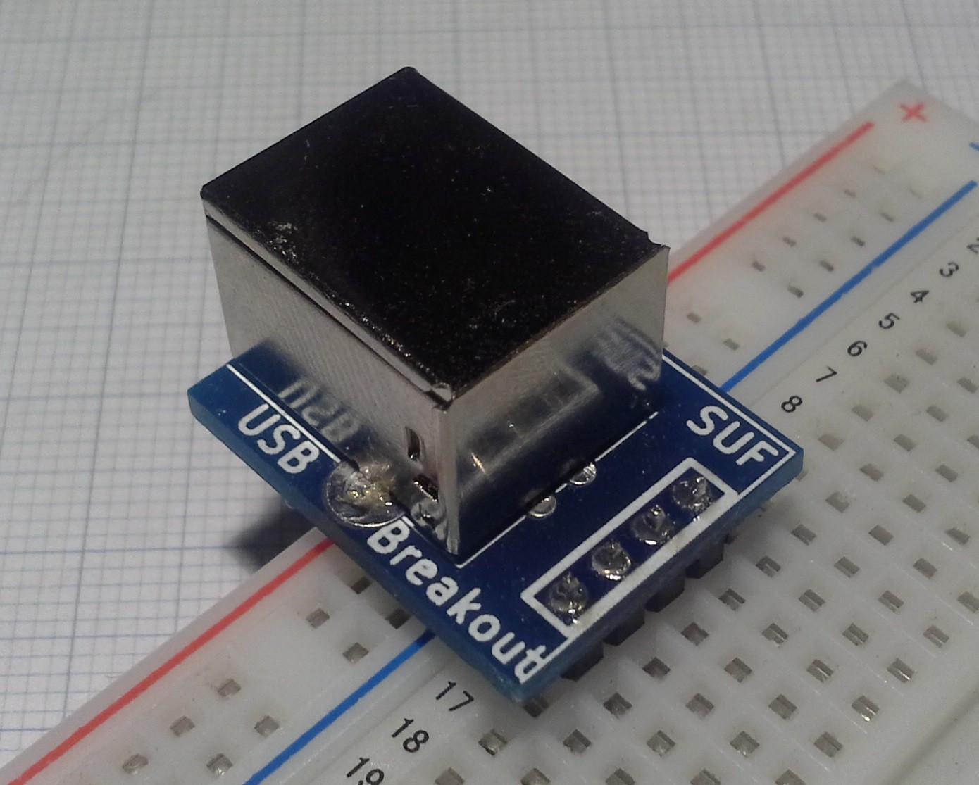
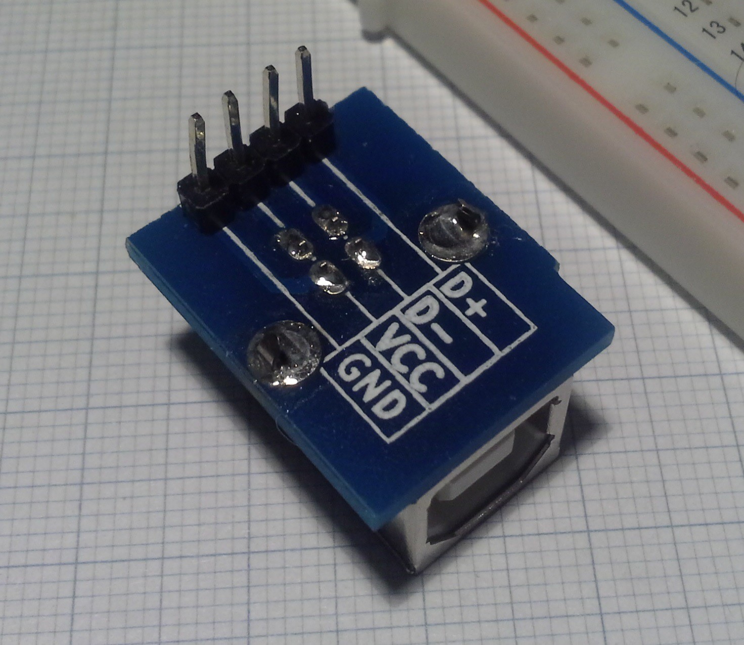
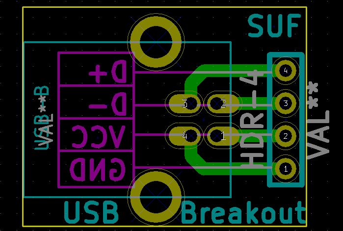
The original repo for this USB-B breakout can be found here. As with the audio breakouts, it has also been merged into this projects repo. And again, the schematic should be obvious from the board file:
I'm thinking about turning the uUSB breakout into a general USB breakout with multiple footprints. That would also mean that I'd have to remove the regulator from the board but then I'd make a separate board for different voltage regulator footprints. Thoughts?
Breadboard Widgets
A collection of widgets/adapters/breakouts to make prototyping easier/faster
 Stefan Lochbrunner


