Jithin
-
ESP8266:Using the JeeLabs transparent TCP-UART bridge
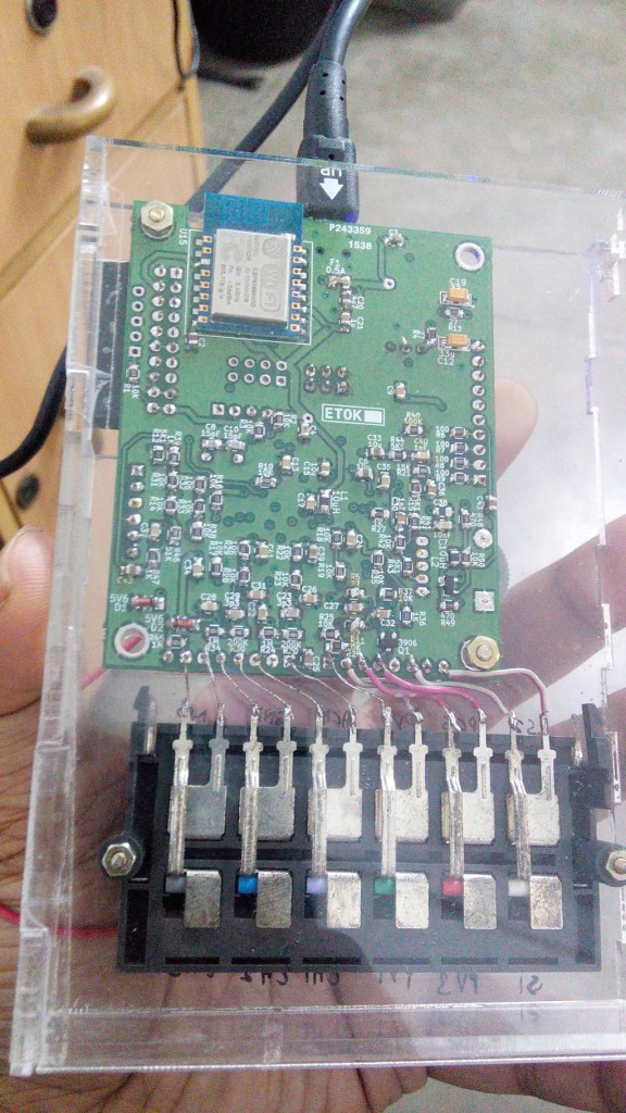
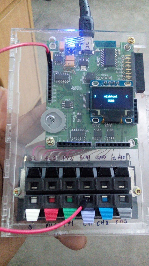
11/10/2015 at 05:31 • 0 commentsEveryone on this site is familiar with the ESP8266 module, and I'm grateful for the community effort towards developing application software. In particular, the ESPHTTPD web server, and the Transparent WiFI-UART Bridge ( Based on the former, and featured on the hackaday blog recently ) have been quite useful for me.
With very slight modifications, the JeeLabs software can be used to turn an ESP-13 module into a TCP-UART replacement for the MCP2200 USB-Serial convertor, thus enabling wifi operation.
The code running on the ESP hosts configuration pages on port 80, and port 23 can be used to telnet into it and use it as a TCP-UART bridge.
![]()
![]()
On the PC side of things I'm using Python sockets to R/W to the vLabtool via the ESP8266.
fd = socket.socket(socket.AF_INET, socket.SOCK_STREAM)
fd.connect(('192.168.1.4',23)) # I have configured ESP to connect to my NETGEAR Router
fd.settimeout(1.0)

fd.send('xyz')  #sending
print fd.recv(10) #receiving. In case of large packets, use multiple receive calls until the expected number of bytes have been received, because this function may timeout and return partial data.
On the vLabtool side, nothing changes except a jumper position. The ESP supports the 1MbPS BAUD used by the MCP2200, so even firmware changes were not required.
-
Documentation, and interactive help
08/20/2015 at 17:32 • 0 commentsDocumentation for the python module is generated with sphinx, and is bundled with the source. It's also hosted online at pythonhosted.org/vLabtool/
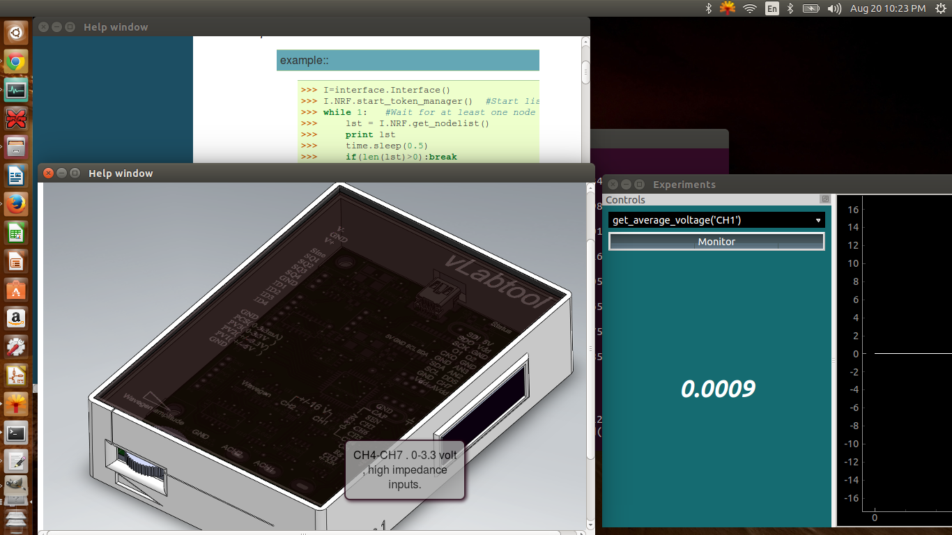
In addition to this, the experiment framework has been modified to display a custom webpage for each experiment.There is also an imagemap of the vLabtool that shows tooltips on mouseover on various regions
![]()
The interactive tooltips are made with CSS and HTML, and I learnt this from http://www.websitecodetutorials.com . The webpage is embedded using QtWebKit.
Here's a shortened example of my code for that map if you want to implement something similar.<!DOCTYPE HTML><html><head><meta charset="UTF-8"><title>Image Map for the vLabtool</title> <style type="text/css"> body{text-align:center;} h2{position:absolute;top:0;left:0;font-size:25px;margin:10px 0 0 10px;} #map { position:relative; height:620px; width:800px; margin:0px auto; background:url('_images/SWrender.png');} a:hover { visibility:visible; /* Fixes IE6 Bug */ } .wavegen_amp { position:absolute; left:96px;top:385px;width:100px;height:60px; text-decoration:none;color:#000; } .wavegen { position:absolute; left:270px;top:300px;width:40px;height:40px; text-decoration:none;color:#000; } .wavegen_amp span ,.wavegen span{ position:absolute; left:-999em; opacity:.8; /* FX/Opera/Safari/Chrome */ -ms-filter:"alpha(opacity=80)"; /* IE8 */ filter:alpha(opacity=80); /* IE6/IE7 */ border-radius:8px; box-shadow:#201 2px 2px 6px; } .wavegen_amp:focus span,.wavegen_amp:hover span ,wavegen:focus span, .wavegen:hover span{ left:00px; top:30px; width:150px; padding:10px; border:2px solid #201; background:#aaa; } </style> </head><body> <span>Mouse over for details</span> <div id="map"> <a href="#" class="wavegen_amp"><span>Amplitude control for the waveform generator</span></a> <a href="#" class="wavegen"><span>Programmable waveform generator output. eg. set_sine(3000.25)</span></a> </div> </body></html> -
System Diagram & State of development
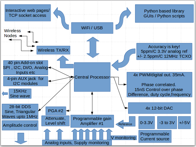
08/16/2015 at 06:27 • 0 commentsFlow Chart
![]()
What works?
2-channel oscilloscope with a variety of different calibrated inputs
+/-5V , 28-bit waveform generator with manual amplitude control.
15KHz sine wave generator
Programmable voltage sources(1-3) , programmable current sources.
4-channel Logic Analyzer.
Frequency counter. Tested Up to 32MHz.
4-channel , phase correlated PWM outputs. Servo motor control.
I2C, SPI expansion bus.
Capacitance Measurement.
Time interval measurement.
NeoPixel output.
24-bit ADC add-on.
Wireless nodes:
ADC
I2C interface
A variety of Python based Apps.
What doesn't?WiFi mode . This has only been tested vaguely with the SDK9.2, and has been documented as a different project.
It's not an active feature for now.
What needs improvement?
DAC calibration routines currently do not store calibration values to flash. They use nominal values, and non-linearity errors up to 10mV have been observed on the 0-3.3V programmable voltage source.
pF range Capacitance measurement routines with the CTMU need to be calibrated.
Standalone Mode is a work in progress, and some form of user input switch which can be added at minimum cost needs to be thought out. This mode also does not load calibration constants, and uses nominal values for scaling.
The android app is also a work in progress.Packaging: Injection Moulded Cases to be manufactured
Pending jobs
WiFi support.Android App.
A better framework to encourage user contributions.
Support for a wider array of Add-on modules ranging from Breakout boards to Lock-in amplifiers.
Developing an array of innovative experiments, and prove how powerful such an architecture can be.
-
On Android
08/14/2015 at 20:00 • 0 commentsAdding android functionality will mean instant portability for the unit. This will obviously mean that the user won't have the freedom to easily write their own code, but useful apps such as oscilloscopes, and control panels can be coded.
ttyACM devices such as the vLabtool are supported by a variety of android phones and tablets with USB-OTG support.
A basic communication test has been carried out, and further development has been pushed down on the priority list. -
Calibrating the DACs ( Programmable voltage sources)
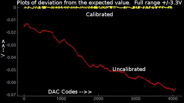
08/13/2015 at 08:22 • 0 commentsDACs have non-linearities that are repeatable, but are not usually periodic. Hence, generating a single calibration polynomial is difficult (At least up to a few orders ). A lookup table is the general solution for making an accurate programmable voltage source. Read more about INL errors here
The following image shows the deviation of one of the programmable voltage sources (resolution 1.6mV. +/-3.3V range) from the expected value(red trace) , and the accuracy of the same post-calibration(yellow trace ). The PIC has copious amounts of flash, and lookup tables and calibration constants can stored in it and loaded by Python upon initialization.
![]()
The overall slope and offset is caused by the amplifying op-amp and corresponding resistors, and can be fixed with a second order polynomial easily.
The jagged shape however, is a property of the DAC itself, and is corrected using a lookup table that stores the error in each code in terms of number of codes to skip forward/backward in order to achieve the highest resolution without compromising on accuracy.
*As of this writing, the DAC calibration data is being loaded from text files for testing. They have not been written onto flash memory for the three units I've shipped to SupplyFrame for the Best Product Prize.
-
Bill of Materials
08/12/2015 at 19:14 • 1 commentFor developing the prototypes, I've sourced parts from a variety of dealers, but for the sake of uniformity, the following table has been generated with most prices obtained from element14, with a few exceptions.
Total Price : $47
Package Designation Quantity rate(INR) Price USD
(100 pcs/batch,
Element14 )SOIC-8-N MCP1725 1 40 0.63 SOIC-20-W MCP2200 1 130 2.06 TQFP-44 PIC24EP64GP204 1 350 5.56 SOIC-8-N TL082 4 10 0.63 MSOP-10-0.5mm-hand AD9833 1 625 9.92 SOIC-8-N 6S21 1 70 1.11 SOIC-8-N REF196 1 205 3.25 MSOP-10-0.5mm-hand MCP4728 1 125 1.98 SOIC-14_N LM324 1 10 0.16 SO-16-N MCP6S28 1 135 2.14 SOIC-14_N 74HC126 1 10 0.16 SOT-23-6 TC1240A 1 50 0.79 SOIC-8-N ICL7660 1 20 0.32 SOIC-8-N LM358 1 10 0.16 SM5050 WS2182 1 10 0.16 SO-16-N CH340G(option) 1 0 0 ESP12 ESP8266(option) 0 0 fox924 FOX924B 1 150 2.38 NRF24 NRF 1 50 0.79 Crystal_HC49-U_Vertical 12MHz 1 5 0.08 Crystal_HC49-U_Vertical 8MHz 1 5 0.08 Fuse_SMD1206_Reflow 0.5A 1 7 0.11 SOT-23-EBC 2N3906 1 2 0.03 Diode-smd 1N4148 1 1 0.02 Diode-smd 4V7 2 1 0.03 0 TantalC_SizeC_EIA-6032_Reflow 100u 4 10 0.63 myTantalC_SizeA 33u 2 7 0.22 myTantalC_SizeA 10u 1 2 0.03 C_0805 10u 1 2 0.03 C_0805 4u7 2 2 0.06 myTantalC_SizeA 1u 2 2 0.06 C_0805 0.1u 26 0.2 0.08 C_0805 .01u 3 0.2 0.01 C_0805 15pF 4 0.2 0.01 C_0805 3p3 2 0.2 0.01 0 R_0805 1E 1 0.1 0 R_0805 27E 2 0.1 0 R_0805 100E 9 0.1 0.01 R_0805 1K 7 0.1 0.01 R_0805 1.2K 1 0.1 0 R_0805 5K1 2 0.1 0 R_0805 10K 22 0.1 0.03 R_0805 20K 1 0.1 0 R_0805 51K 1 0.1 0 R_0805 200K 2 0.1 0 R_0805 1M 2 0.1 0 0 2mm-socket Chx 6 5 0.48 MYPin_Header_Straight_2x10 CONN_02X10 1 10 0.16 Pin_Header_Straight_1x10-oval Analog I/O 1 10 0.16 Pin_Header_Straight_1x10 DIO 1 10 0.16 myPin_Header_Straight_1x06-oval CONN_01X06 1 6 0.1 Pin_Header_Straight_1x03 V+/V- 1 3 0.05 slider-pot slider 1 10 0.16 aux-4pin-smt I2C 1 20 0.32 myUSB_MINI_B USB-MINI-B 1 10 0.16 Jumpers 1E 7 0.1 0.01 PCB pcb 1 200 3.17 Cabinet box 1 500 7.94 Cable USB-AtominiB 1 30 0.48 47.09 The total cost excluding shipping stands at less than $50.
*Optional components marked as zero value.
-
Testing on Raspberry Pi
08/11/2015 at 20:34 • 0 commentsThis project was originally envisioned as RPi2 specific, and prototypes were developed which included the 40-pin header on the vLabtool itself. However, it was later decided to stick to USB, and make the software work with the RPi2 since it has 4 USB ports, and one can be dedicated to the vLabtool.
Some problems were encountered, and deemed necessary a few firmware changes. The receive buffer of the RPi is much smaller than full blown desktops, and this caused overflows, and data loss. The software has to bring large datasets after splitting them into smaller chunks.
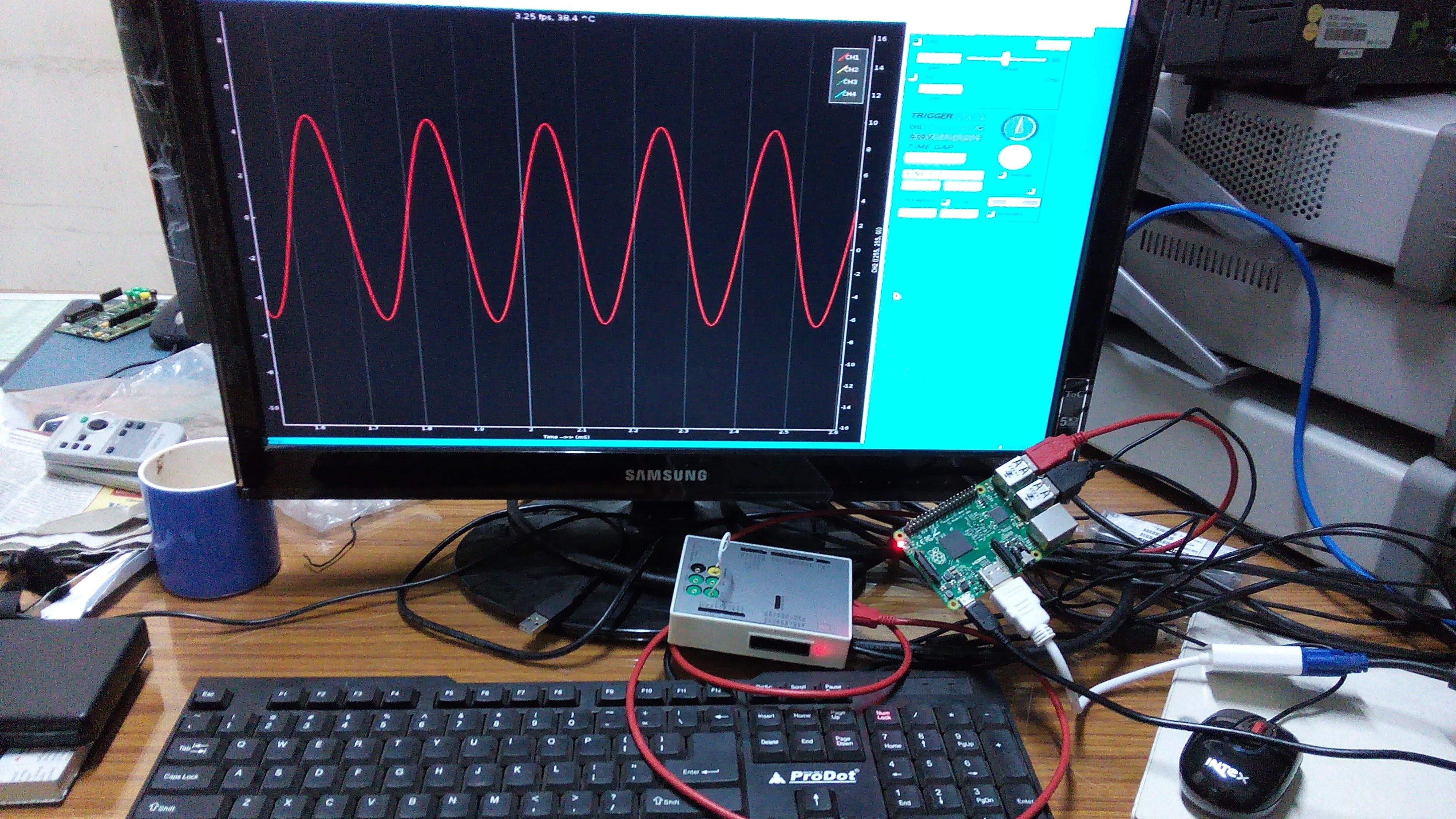
No detailed testing has been carried out yet, and here's a picture of the oscilloscope GUI running on an RPi2.
![]()
-
A few basic electronics experiments. With GUIs
08/11/2015 at 19:55 • 0 commentsFilter study
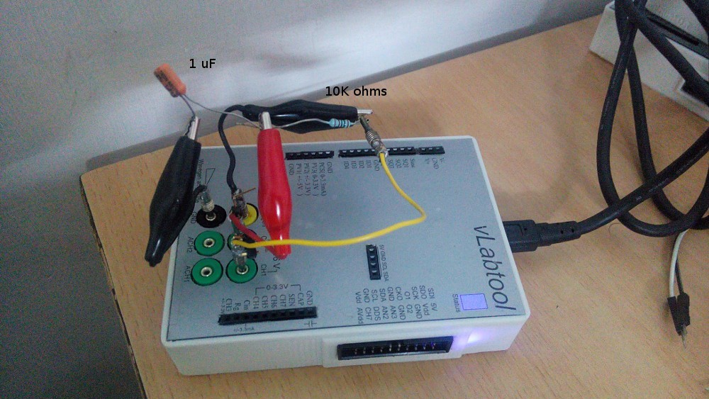
A simple low-pass RC filter was made with a 10K resistor and 1uF capacitor. The input was taken from the programmable sine wave generator, and simultaneously monitored via CH1 . The output(midpoint of R and C) was also monitored via CH2.
Frequency was swept from 10Hz to 500Hz, and the amplitude and phase plots are shownPhotograph of the setup:
![]()
Diode IV characteristics
A 4148 diode's IV characteristics are plotted.
Input is taken from a 0-3.3V DAC (PVS3) , and fed to a 4148 diode via a 1K resistor. The other end of the diode is grounded via a current to voltage convertor.IV plots are obtained by plotting the voltage across the diode versus the current
-
Monitoring low amplitude outputs via CH3
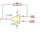
08/10/2015 at 21:54 • 0 commentsCH3 is specified as a +/- 3.3 V analog input with up to 32x programmable gain.
However, the schematic for the input signal processing stage looks like this![]()
*A 10MOhm pull down resistor is also present on CH3, and is not shown
This functions as a unity buffer if Rg is left floating, and CH3 is calibrated under such circumstances. But if the user isn't satisfied with the +/-100mV range at 32x PGA, and wishes to obtain an arbitrarily high gain(subject to noise considerations) , then they may ground Rg via an externally plugged in resistor. The gain will now turn into the familiar formula for a non-inverting amplifier (1+Rf/Rg . Where Rf=10K , Rg=user configured)
HB100 Doppler radar output monitoring
Among many other uses, this functionality was used to add another 10x of gain to the 32x internal gain in order to monitor the output of an HB100 doppler radar. The output of this radar is an analog signal whose frequency is a function of the velocity of the reflecting object.
Here's a video of the test
-
First attempt at a 3D printed case
08/05/2015 at 17:51 • 0 comments3D printing is a fantastic tool to rectify errors before investing in an injection mould.
Here are some of the prints I got made from the Maker's Asylum, New Delhi . The lid will be a laser cut acrylic sheet with appropriate markings for all the connectors, but it isn't ready yet.
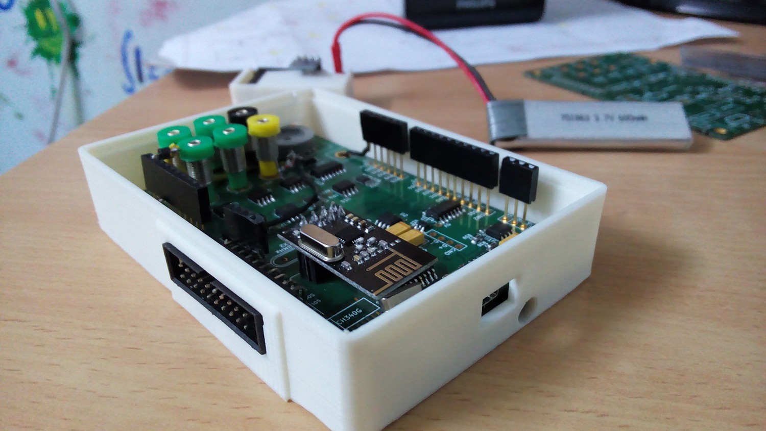
![]()
Image: Enclosure for the vLabtool. Slight errors were found, and a revised design has been prepared
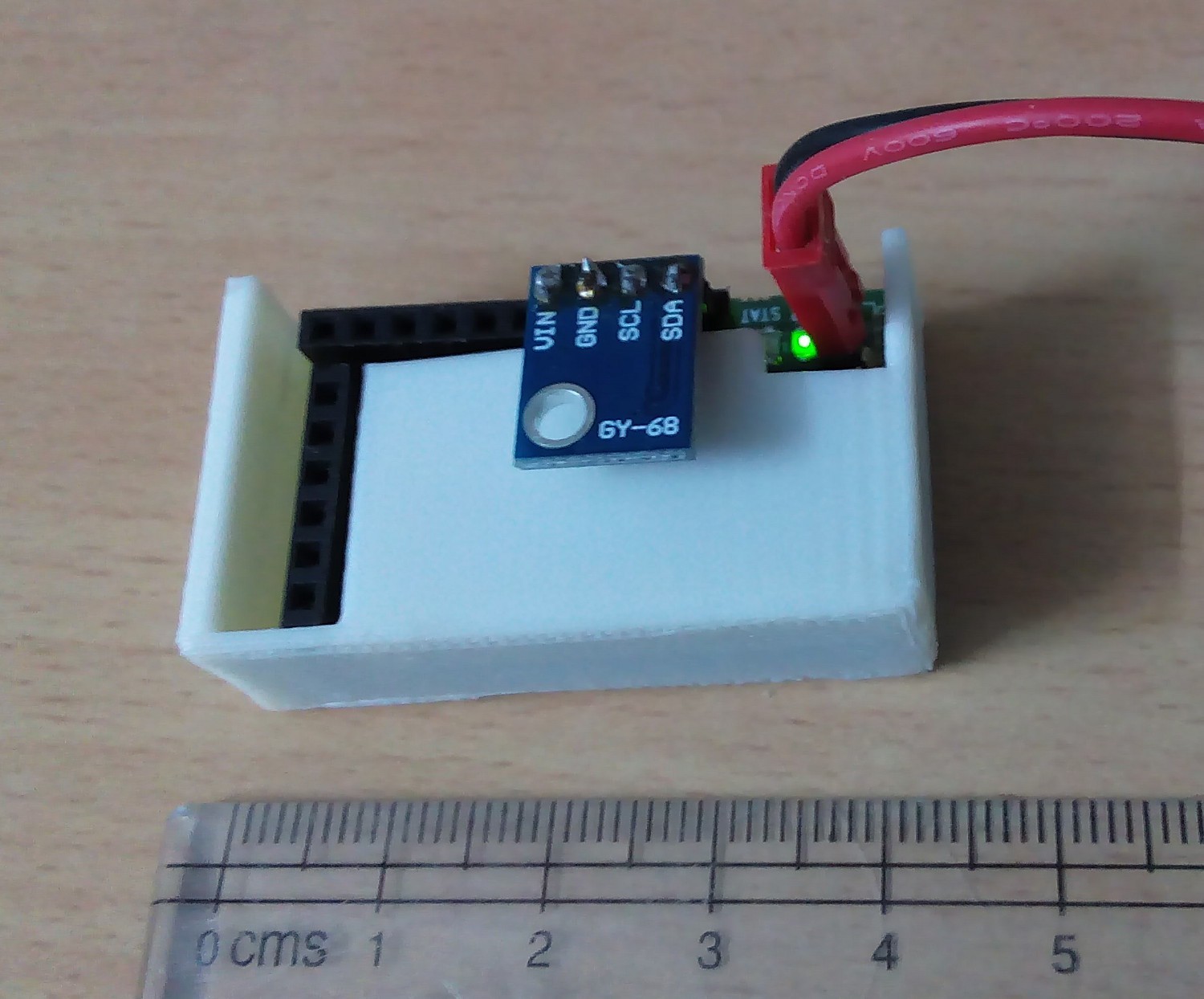
![]()
Image: A wireless node inside its case. An altimeter has been plugged into it.
A Versatile Labtool
A cost effective, multi-pronged data acquisition tool to turn your computer into a workbench for science and electronics experiments.