Hacking the Milight wireless bulbs
Reprogramming its controller board to use my own RF protocol
Reprogramming its controller board to use my own RF protocol
To make the experience fit your profile, pick a username and tell us what interests you.
We found and based on your interests.
Here's a video where i have a look inside my two different bulbs. They're both quite easy to break into without destroying them, which is nice.
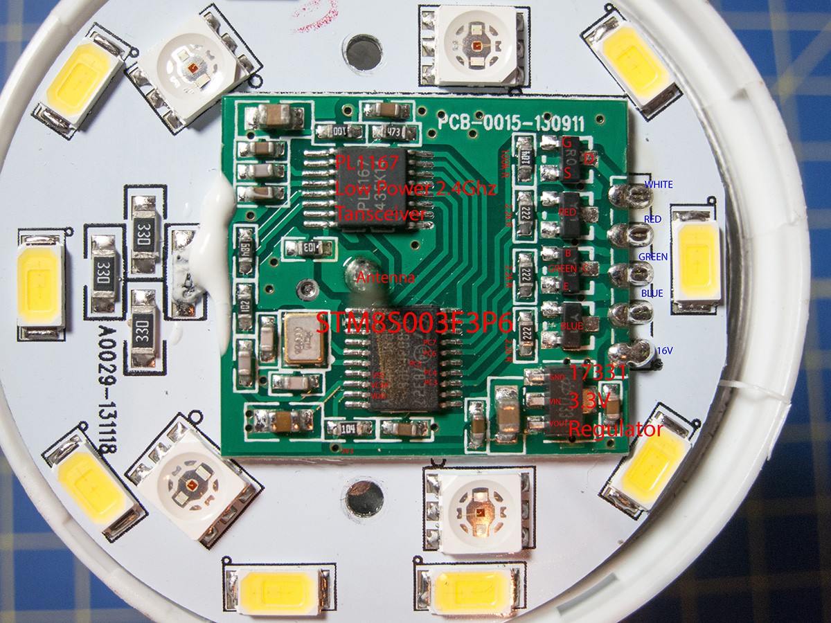
The Milight PCB
Image borrowed from Itay's teardown. My board looks the same, but they're using a white soldermask now. Probably for reflectivity, and also maybe to avoid reflecting green light (but I'm not sure whether that was even a problem before).
So the boards in both of my two bulbs seem to use the exact same circuit, the E14 bulb just has a slightly different layout. They're both using the same STM8S003F3 microcontroller and the PL1167 wireless transceiver, and they're both using the four PWM compare channels available on the STM8's TIM1 timer to control the four transistors driving the four (RGB+W) LED channels.

Controller pinout
Transceiver pinout
The STM8's TIM1 PWM outputs are on some of the same pins as its native SPI pins, so I guess they must be bit-banging the SPI communication between STM8 and PL1167. The SPI pins from the transceiver seem to be wired to PD2 through PD6 on the STM8. I've found several different development boards around Aliexpress and Alibaba using this exact combo of STM8 and PL1167, but they all seem to be using the native SPI. And even so I still haven't found much in the way of code samples for this combo.
I did, however, find another board that was very similar to the one in my bulbs. It has four PWM outputs so I'm guessing it's also using the TIM1 for PWM (ie also blocking the SPI pins), seeing as it's the only timer with four compare outputs. I messaged the seller for code samples posing as a development engineer for a sizeable project, but they won't send me any code unless i order a sample of two boards at 20 usd + shipping. Almost worth it, but since I can't be sure the layout is the same I'm a bit cautious. They seem to be the only supplier, so I guess they're careful with giving out their code to prevent people from cloning their boards.
In my research, I also found a goldmine of tutorials on the STM8 controller including SPI bit-banging, created by user Nevyn of the Netduino forums. These will be very nice to refer to if and when I get started with some actual development.
Create an account to leave a comment. Already have an account? Log In.
Hi
I'm developing an application for android to control milight bulbs by milight bridge. Would you please give me a complete developer guide (specially for AT command set)?
the link http://www.limitlessled.com/dev/ is very messy and confusing!
Thanks a lot
Hi There,
I have had a look a the new dual white RGB led, and it uses a different protocol.
I think it has an expanded protocol compared to the old bulbs, still one way, still the same RF chip, but different channels and sync words.
The repeat and channelhopping seems to be the same, and the sync process between the remote and the bulb is the same.
I have looked further into the data being sent - and it seems there is a pattern as long as the first byte (index 0) is the same.
The following frames has been picked up when pressing on channel 1 on a LOT of times.
The frame seems to be scrambled somehow - but it looks like the bytes at index 6 and eight are the only ones changing when the byte at index 0 is the same. So when looking at the old protocol, these bytes might be the "frameID".
As it is still oneway - and the bulb learns the remoteID when using different remotes, then the "key" has to be sent in the frame.
A long press also changes another byte, index 4, and that is also a bit like the old protocol.
0xb1 0x06 0x8d 0x56 0xc9 0xa8 0xcd 0xca 0xa9
0xb1 0x06 0x8d 0x56 0xc9 0xa8 0xcb 0xca 0xa7
0xb1 0x06 0x8d 0x56 0xc9 0xa8 0xff 0xca 0x4b
0xb1 0x06 0x8d 0x56 0xc9 0xa8 0xea 0xca 0x46
0xb1 0x06 0x8d 0x56 0xc9 0xa8 0xdb 0xca 0x37
0xb1 0x06 0x8d 0x56 0x49 0xa8 0x42 0xca 0x9e long press / repeat
0xb3 0x41 0xd7 0x20 0x37 0x95 0xf0 0xcb 0x31
0xb4 0x1f 0x24 0x37 0xaa 0x15 0xf3 0xaa 0xfe
0xb4 0x1f 0x24 0x37 0xaa 0x15 0x30 0xaa 0x33
0xb4 0x1f 0x24 0x37 0xaa 0x15 0xdc 0xaa 0xef
0xb4 0x1f 0x24 0x37 0xaa 0x15 0xb6 0xaa 0xc1
0xb4 0x1f 0x24 0x37 0xaa 0x15 0xac 0xaa 0xbf
A different key gives this frame:
0xb1 0x06 0x8d 0x56 0xc9 0xa5 0x87 0xc7 0x5d different key than "ch1 on"
Anyone up for a challange to find the "key"?
Martin
I have already done this work! re programmed stm8s003f3 with my own firmware, and fixed some bugs that were in original milight firmware, it took me more than a month working full time on this firmware.
but I've signed NDA, so can't share details.
That's cool, I didn't think anyone on here had worked on this.
Can you share any tips and tricks on the STM8 and PL1167 in general, without breaking NDA?
most important is to hack protocol, my boss spent more than a year on that, If someone can do that, rest is simple C programming. pl1167 is not different from other RF chips, if you have already played with any 2.4GH or Sub-1GHz chip, it is not tough to program this RF chip. it works even with 8051.
Is this project still ongoing? would glad to help with some parts!
Best part would be to have 2 way communication on these lamps!
Hi! The project is on hold at the moment as it turns out I've got too much on my hands with school and work.
Let me know if you get started - I'd be happy to add you as a contributor if you want to submit a project log.
Keep on going on this.
There are a lot of people working on this with limited knowledge (like me).
Maybe this could be a cheaper source for the STM8/PL1167 combo and maybe this seller gives you more information you need:
http://www.aliexpress.com/item/STM8S003-PL1167-LED-dimming-lights-with-a-special-5-way-wall-switch-detects-PWM/32362925729.html?ws_ab_test=searchweb201556_2,searchweb201644_4_79_78_77_82_80_62,searchweb201560_8
Maybe interessing for others: The 9W led bulb has its plasic cover/diffusor glued with silicon.
Hi Magnus, when you get to it, the protocol should take this new bulb http://m.aliexpress.com/item/32559415032.html into account too. It looks to be using the same circuit. Another input could be to have a frame contain the complete setting, color, intensity and off on state, and still use some kind of multicast as they do today. Doing this multiple bulbs will react in sync, and a controller can periodically send out this frame to maintain the current setting even if there has been a power failure.
Huh, hadn't seen that one! The circuit looks slightly different, it has a fifth PWM channel switching a second white channel. So protocol-wise this bulb is probably just emulating two different bulbs - one RGBW and one dual white - to make it compatible with the regular Milight protocol.
Seems like an odd way to do it really, Philips has already proven that plain simple RGB is enough to change color temperature so they could easily just have done color temperature in software instead by mixing in some yellow with the white light.
Yep - it is also marked as new.
Instead of thinking about how they did it - wouldn't it be better to think about how it can be improved when implementing a customized protocol.
And with the appearance of a new bulb it would be silly not to take it's features into account.
And you are right about the fifth channel, but that really doesn't make a big difference, other that it needs to be added as a parameter too.
Regarding the protocol, as I mentioned previously, it would be nice if a frame contained all necessary parameters to get the bulb in the desired state eg.:
iSyncWord1, iSyncWord2, iFrameNumber, iChannelNumber, iRpwmValue, iGpwmValue, iBpwmValue, iWWpwmValue, iCWpwmValue, bBulbStateOnOff
In the original firmware the frame is being re sent on three RF channels with a repeat of 50 times (I think), this way seems to be quite reliable, and doing it this way multicast will still be supported making several bulbs act as one.
If the frame contains all necessary information, then having a controller periodically send out this info for each bulb will make it easy to maintain the settings when using the bulbs in e.g a home automation project.
Can I ask what your time schedule looks like regarding this project?
You mentioned an EV board - have you considered using a cheap ST link clone and an actual bulb for developing?
STLink: Sure, i have an STLink on the way, should arrive any day now. I'm still waiting for the WiFi bridge too, so as of yet i actually have no means of controlling the bulbs.
Periodic updates: I'll probably be saving the bulb state to EEPROM like they do already so there's no need to periodically send out the states. And since the bulb actually has a transceiver (not just a receiver), I'll also experiment with having the bulb announce to the bridge that it's come online and requesting an update on the current wanted state (in case the setting was changed during the time it was off). But if that doesn't work out periodic updates are an option for sure.
Channels: For light selection I'm thinking there will be an 8 bit room/house code and an 8 bit light code, allowing 256 "rooms" with up to 256 lights each. And I'll probably use light number 255 as a broadcast to all lights with the same room code (drawing some inspiration from the Internet protocol).
Colors: I'm still not sure how I'll implement the colors. There will have to be straight up RGB control for sure, but how to enable the color temperature is a big question. I'm not sure that direct access to the PWM is the best option here. The RGBW and RGBWW lights obviously have the exact same circuit and firmware, but the LEDs are different so setting the same PWM values would yield a completely different color any time you're using white light. These new RGBW/WW lights complicate things even further so I'm open to ideas. Maybe multiple separate control protocols: one for regular RGB, maaybe one for HSV and then something for white light with brightness + color temp (and probably also green/magenta "tone" to allow us to span the entire 3D color vector space). These would then be abstracted and interpreted to use different firmware implementations in the different bulbs.
In any case, there will have to be some limits to the control since we can't run everything at the same time. If we run all RGB + W LEDs at full power on say my 6 W bulb, it would use somewhere around 11 W of power and probably burn out, either from heat itself or from overloading the integrated power supply. Or best case scenario it'd just work intermittently if there's overcurrent protection in the power supply. So there will have to be a compromise somewhere between control and power usage.
Schedule: Work on this project will unfortunately be slow for a while now as I need to study for my January final exams.
I also gave the maximum power consumption some thoughts - and yes, that must be handled by the device protecting itself.
It seems you have some experience regarding the colors or at least giving it some great thoughts - that sounds promising
Perhaps you should go all in, and reserve 16bits for "rooms" and "lights" each. Better safe than sorry.
The original bulbs can be "locally" operated on power on off, and this can cause it to come out of sync when using a home automation solution.
The "local" features is also nice to have.
Yeah I also thought about maybe expanding the room codes as 255 isn't a lot if (but that's a big if!) the protocol becomes common. But I also want to keep the word length reasonably short.
Local on/off using regular light switches will be there in some way for sure, that's the one demand my wife has. ;)
To expand on the "bulb coming online message" feature, I'm thinking all the current states could be stored in the WiFi bridge and sent to the light as soon as it signals that it has come online. But that might also lower the Wife Acceptancy Factor since my wife expects the light to come on if she cycles the switch, regardless if home automation thinks it should be on or off. So this will have to be iterated upon to come up with a good compromise.
The bulb signaling "hey here I am" seems clever, but what happens if the is a power failure, then your handling begins to be quite demanding - listen before speak etc...
And then you can't clone a bulb as you can with the original software - instead you will have to broadcast to all the bulbs in the same room, but then "room" might not be the right name - then it more or less is a group.
I have some of the bulbs installed for outdoor lighting, and they appear as one, and that looks really good.
A big problem with the current firmware is synchronization with my controller on restart of my system. I need to drive each bulb to max light level (that is one command) and then all the way up in color level (that is 10 transmissions) and then I can step the color and light level as desired. All this takes up to 2500ms per bulb/channel.
All this takes time, but after this each bulb is in a well known state.
This is the reason why I think one command with all parameters would be a nice thing.
A pairing mechanism like the one already used also seems good to have. Then it is easy to modify the setup without having to rebuild the firmware all the time - A firmware per bulb type perhaps, and setup done run time.
Yeah teaching the light will definitely be performed without touching the firmware, maybe using the exact same procedure the Milights already use.
Using room codes for grouping/cloning is already a lot more flexible than the Milight groups. With milight you only have four groups and no way of controlling lights individually (unless they are alone in their group). In your case, you would use one room code for all your outside lights and broadcast any settings just like you do now. The difference is you also have the *option* of controlling them individually. This is why i think 8 bits is more than enough for the light codes, because very few people will ever want to group more than 255 lights together. :)
Power outages and, more generally, multiple bulbs coming online and "speaking" at the same time would surely need to be worked out. But there are a few different ways around it that are well known in Network theory.
Using the authometion.com library you can actually partly archive the same with unique addressing and multicast, instead of room number it is just the address of the bridge you change, and this is 16bit, you then have four channels and a multicast.
Sync words can also be different to expand the system.
Zones and channels are easy to manage in an upper layer, but a big flaw in the original protocol is the lack of setting a certain level of light or white colour. Instead it is done by stepping up and down. Surely it is due to the simple remote.
Cool! I am looking forward to your progress. The ultimate option would be to reprogram the existing controller and then write to factory and ask i they could make a custom edition or even better have them make an Arduino compatible chip version :) Looking forward to your progress.
Hej Mads! Tack! I checked out your site and I love your work, you seem to be working with really cool stuff!
If this amounts to anything, contacting the factory about it could surely be an option. And if they won't do it, I'm studying in Lund just across the Öresund (I can even see CPH from here!) so we could probably work something out to get your lights programmed as well. :)
Another option for sure would be an Arduino-compatible board with an Atmega controller, but since the boards have slightly different footprints those would probably have to be tied to a single bulb. Not sure if the factory would bother as this feels more like a consumer-oriented product with the app and all that. But the STM8 controllers seem pretty easy to work with, at least if you've used microcontrollers outside of the Arduino space. And if only the RF protocol is "good enough" we won't really need Arduino inside the lights. ;)
Quick thought, could there be an Atmel chip that is pin compatible that could make a arduino firmware?
I'm not sure if Atmel has a pin-compatible
chip, but the similar 8-bit Atmegas I've used never have this many
PWM channels, especially not on a single timer. The first thing i looked
into was using only an ESP8266 but those only have two PWM channels. Wonder how autometion got around that.
using the esp8266 arduino tool chain there is pwm on all digital outputs..
Ah, gotcha. Must be using software PWM then, because if I'm reading the datasheet right the 8266 can only do two simultaneous PWM outputs in hardware.
Hi Magnus, cool project. I was thinking about doing something with the milight bulbs as well. I came across the authometion.com products. They have just added an esp8266 version, which seems quite neat. But that leaves the stock milight bulbs behind. I have asked if they can sell the controller board alone, so the existing bulbs can be updated. Doing a firmware update with enhanced protocol and features on a stock bulb also seems cool. I think the standby current might be lower on the stock bulb. Authometion.com has made an arduino library that works with the stock bulb, maybe that could be used as an inspiration for a controller.
Hi! Yeah the power consumption in these low-power modules is always a
lot less than a full-on WiFi chip - The ESP8266 in transmit mode uses
10 times the current of this PL1167. But that's more of an issue for
battery-powered projects.
Thanks for the links, I noticed autometion also have (or used to have) a light called LYT 88 which was also just another brand of these Milights.
Become a member to follow this project and never miss any updates
By using our website and services, you expressly agree to the placement of our performance, functionality, and advertising cookies. Learn More

 Hulk
Hulk
 Yakroo108

 Ken Yap
In the pictures the PCB looks similar if not the same to the PCB of the lyt8266
https://authometion.com/shop/en/home/13-lyt8266.html
the sell the WiFi board with the led drivers separately. Maybe easier to just retrofit the milight bulb? Though not as exiting I admit