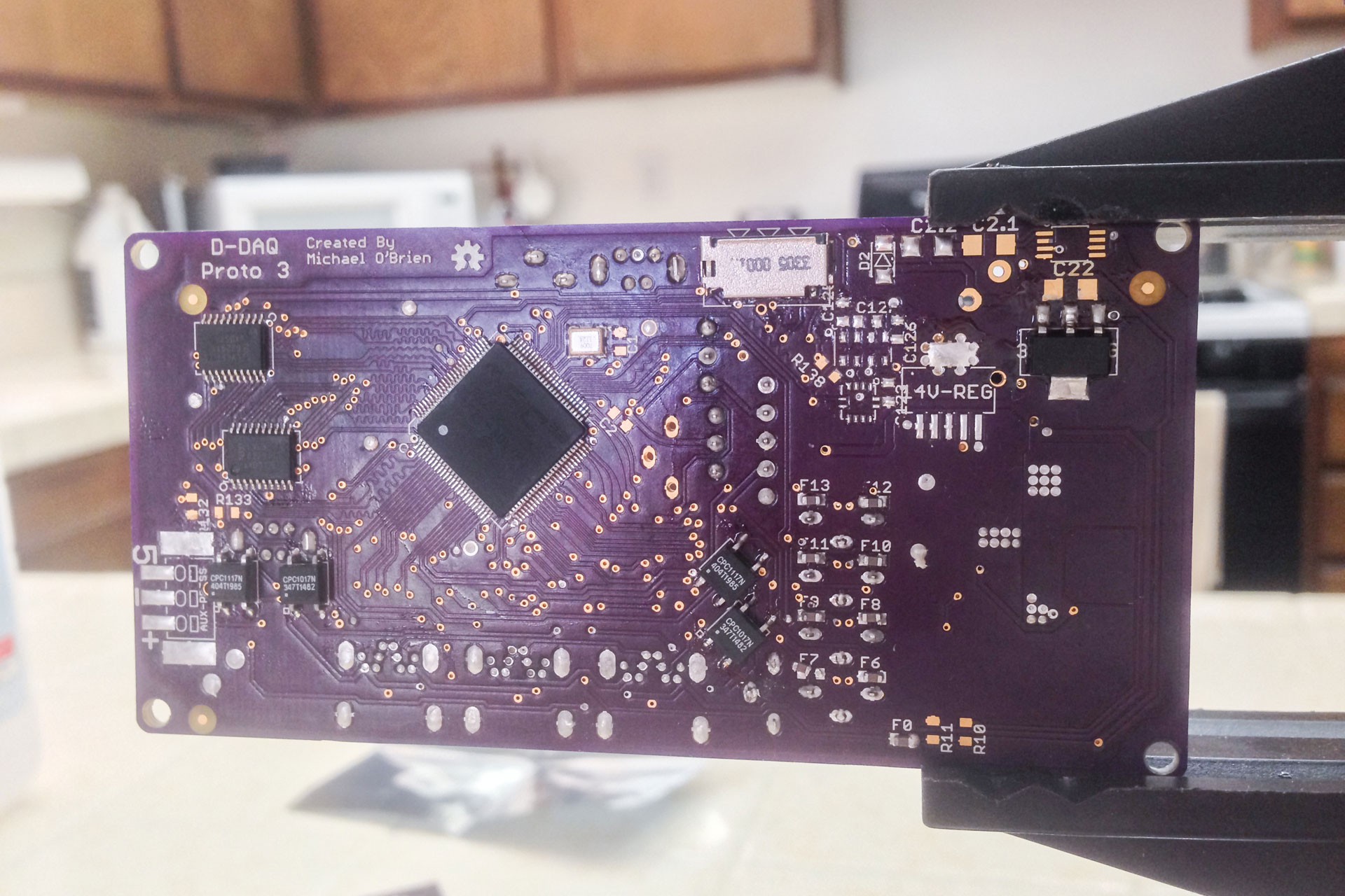
Michael O'Brien
-
Proto Version 4 Schematic Capture
07/23/2014 at 06:02 • 0 commentsFinished this puppy up. Contrary to what I was initially planning, I am not revising the board design to incorporate an off-board power supply subsystem.. If needed that'll happen down the road though. I have though come across numerous little bugs that I was not aware of or overlooked previously. Moreover, I feel I've significantly improved the base design of D-DAQ. Anyhow, the changes are as such:
Changes/Corrections/Bug fixes:
- ICSP lines need to have less than 100 Ohm resistance but have 470 Ohm PTCs on them. Added an additional pair of SSRs to 'drop in' a pair of 100 Ohm resistors in parallel to the PTCs giving a parallel resistance of ~82.5 ohms. Hopefully this will be low enough
- ICSP detection only engaged programming lines and MCLR. There was no indication to the PIC32 that the cable was plugged in so the programming lines remained AN inputs. This has been corrected.
- Due to apparently high noise automotive environment, decoupling capacitors were revisited. I was going to use decade pairs of 100 nF (0.1 uF) and 1 nF caps. However, at 7 pairs for just the PIC32, 9 for the whole board, this is a lot of board space and. I'm moving to using 4x 0.47uF feedthrough caps for decoupling..
- Using spare GPIO pins to bit bang a SPI interface
- Moved to a parallel-in to serial-out, 8-bit shift register for button support for the displays. As B1 on each display occupies the MISO line on the SPI interface to each display, this means 6 of the 8 bits are used. Soft SPI used for access. It's about the size of the accelerator so it won't use much space.
- SPI-SSx pins are now utilized as GPIO's, but dedicated to the current displays to toggles the display driver between command and data. Previously these were tied to ground and because I didn't know they could function independentlyf.
- Calculations show a best case scenario of ~2 Ksps with the I2C-to-SPI interface. Though slow, it yields a max 4-stroke RPM of ~6350 and 2-stroke RPM of ~12.7K. Though quick, this is under many red lines of performance gasoline engines. A faster interface is required so the IC is tossed out and I'm moving over to Soft SPI.
- To set a limit, even though motorbikes don't typically have a daq, 20K RPM seems to be a solid upper limit for gasoline engines. This requires a sample rate of ~6.67 Ksps. Due to the bit depth of AN channels being 10, I'll be oversampling 9 times giving me a solid 60 Ksps and output 12-bit values. This gives me a streaming output rate of ~1.1 Mbps.
- Moved to a parallel-in to serial-out, 8-bit shift register for button support for the displays. As B1 on each display occupies the MISO line on the SPI interface to each display, this means 6 of the 8 bits are used. Soft SPI used for access. It's about the size of the accelerator so it won't use much space.
- Due to possible streaming buffer issues, the 10ns, 1-Mbit SRAM IC has been upgraded to a 8ns, 4-Mbit chip that costs 2x as much and uses 35-50% less power to drive. This is also enough memory to buffer a single 24-bit frame at 480x272, which will be a theoretical limit for display size. As its possible to drive the PIC32MX to 120 MHz, this SRAM chip will still be able to clocked 1:1 with the CPU and P-bus. Each line has a serial termination of 140 ohms. Due to board space, 0402 resistors are used.
- Analog ground is connected to digital ground through a lossy filter. I'm using 0603 SMD ferrite beads with stated impedances of ~120 ohm @ 2 MHZ, 330 ohm @ 20 MHz, and 470 ohm @ 100 MHz.
- They should attenuate the first few odd harmonics of both my SPI and PMP interfaces fairly well by themselves. But if not, I'll solder in parallel capacitors to make LC filters.
- Crystal changed out from 16.368 MHz @ 0.5 ppm to 40 MHz @ 2 ppm to enable USB and maximum clock of 120 MHz if end user so desires. Though absolute timing accuracy is decreased, relative timing is minimally affected and greater functionality is obtained. I could not find any 20 MHz, 2ppm or better oscillators.
- DISP-1 now has hot-plug detection
- HPD pins now have pull ups. They should only be pulled down on a display board, not an adapter board.
- Though I'll test in the MPLAB X simulator, I believe I can add a 3rd Input capture. This means direct monitoring of RPM, Vehicle Speed Sensor, and for some of us diesels, fuel injection. I'm sure there is an equivalent on the gasser end, but I don't have one as a test bed right now.
- JTAG Header is now 5 pin instead of 4 so MCLR can be utilized by TRST and programming D-DAQ via JTAG is possible instead of just boundary scan and debugging.
- PIC32 package up-sized to 14x14 mm to allow for 8 mil traces and 8 mil spacing all around.
- Net classes have been defined and will be enforced on board layout
- min - 6 mil width, 13 mil drill, 6 mil clearance
- analog - 10 mil, 15 mil, 10 mil
- digital - 8 mil, 15 mil, 8 mil
- power-low - 16 mil, 15 mil, 10 mil
- power-med* - 24 mil, 20 mil, 16 mil
- power-hi* - 32 mil, 25 mill, 20 mil
- Status LED Added due to freed up pins!!!! =D
- Changed over several symbols to standardized practices. Kept a few as I've made them (the PIC32) because it'll take too much time to redo and then I have to figure out how to group things as pin declarations change as this evolves...
- Though not standardized, I have the schematic capture split up into pieces that represent different sections of D-DAQ. This is for anyone wanting to get acquainted with D-DAQ.
- Fixed uSD Card footprint. I had 2 Molex datasheets sitting in my folder and used the wrong one or bought the wrong part...
- Changed SMPS feedback resistors. I'm still within spec according to the datasheet, but I'm using one of both 499K ohm and 158K ohm resistors. I already have a precision 100K ohm in the circuit and that drops the 499K to a 316K ohm. One less unique part :)
- I'll clean up the BOM in a few days.
This has taken the better part of 3 days' work to overhaul, double check, and research. The schematic capture is updated, but there is no board layout to go with it at this time. Because I have theoretically decent EMI filtering from 2 MHz and above on the analog ground and have personally 'discovered' feedthrough capacitors, I'm comfortable starting the sensor board layouts. I know I said I'd start them more than a month ago if memory serves, but now I have a fair amount on confidence that I know which devices and filters I can use for helping with noise immunity. That being said, I need to figure out band pass noise suppression techniques for some of these sensors.
-
Board Revision in Progress
07/20/2014 at 03:49 • 0 commentsJust an FYI here. I'm going back and forth defining pins in MPLAB X and cross-checking this with my existing schematic capture. There aren't direct inconsistencies, but several footnotes as to things being executed in a better manner are popping up in my head.
Right now I'm focused on fixing some display-related pin functions, moving to a separate analog and digital grounds, and changing some GPIO's to different sides of the PIC32 so routing is simpler. Based on the space of the current boards, I'm going to stick to the existing layout for the most part but routing will be much different. Due to these individual items, I'm taking the time to clean up the schematic so it's not a mess and is easier to read. Mind you, it'll still be complex with a 100-pin package on board.
I have a big technical hurdle I need to decide upon which is deciding how to log data. Right now I have a best case scenario of 2.5 Ksps which might sound like a lot, but isn't. I'm thinking I'm going to have to move over to a soft SPI, aka bit banged SPI interface of ~5 MHz would yield me 10x that at least. Either way, re-appropriations give me 6 extra GPIO pins at the moment so who knows.
-
The Toolchain & Other News
07/18/2014 at 17:53 • 1 commentSo, way back when I first settled on the PIC32, I knew I needed compiler support for the MIPS architecture. Let alone, it's building a cross compiler which is usually not an easy feat. My purpose with D-DAQ is to give back to the/a community and make sure there is something they can use unencumbered. Right now, thats not completely possible. If I used ARM I wouldn't be having this problem now, but at the same time I don't see a need to change.
Edit: Sorry about the atrocious grammar
First off, I want to give some more light to a controversy that isn't well publicized. Microchip's primary compiler for the PIC32 is XC32; previously it was known as C32 but there were code changes etc etc which lead to a name change but they're functionally the same and I'll use 'XC32' to refer to both. Like any 'decent' piece of commercial software, there are licenses available for purchase for the functionality of which you choose to use in the product. The controversy that exists though is that if you don't have a license, XC32 will disable/remove GCC's own standard optimizations i.e. -O -O1 -O2 -O3 -Os. Even if you don't explicitly define the levels, most of the individual flags are disabled by the function that currently resides at gcc/gcc/config/pic32/mchp.c:1081 in version 1.31 of the XC32 sources.
mchp_override_options_after_change
Frankly, this is a bit irksome; being charged for something that is normally free. I'm not the first person to bring this up either. I've known about it for a couple years because some searching yielded a blog post from back in 2009 when it was just the C32 compiler. About 2 years later it was noted again for the XC32 compiler. It was also briefly discussed on the EEVBlog Forums. Oh, and toss in a final thread on Microchip's forum. However, this is half of my point.
I want people to be able to code for D-DAQ. That cannot happen without proper PIC32 support. ARM is much more prolific because it's toolchain is not encumbered like the PIC32's. If I were looking at just doing some small projects off of a 'beefy' MCU/uC then I'd have no problem with using MPIDE or UECIDE to develop my code on. The problem, though, is that before I can code, or more properly while I code, for D-DAQ I have to make the libraries themselves for complete peripheral support. Why? I'm using both I2C busses, the PMP bus, 3 of the 4 SPI busses, 14 ADC channels, 2 Input capture pins, and even DMA to attempt make this little PIC32 do what I want. The Arduino compatible libraries in the other IDE's do no have support for even half of these peripherals (excluding the ADC).
If I had the time and help, I'd get started on developing proper libraries for the PIC32 for MPIDE and UECIDE. But I have neither the time or help currently unless I pull out of the HaD Prize competition. Frankly if I drop out of the competition, it's unlikely that I'll complete D-DAQ.
What I've decided to do is this: Due to the time constraints, is to develop with MPLAB X. After all I get 60 days of the 'Pro' license. Following the completion of the contest and regardless of outcome, I know I have a helping hand or two who can assist me greatly. From there I look to porting or developing libraries for utilizing all of the PIC32MX's peripherals to more open environments. Microchip already has no problem releasing unencumbered variants of their compiler, look at chipKit, but there just needs to be proper support to keep it up to date.
Footnote: For the apt, it's trivial to bypass the license restrictions. I'm not touching this topic here because that's not within the scope of D-DAQ and I'm not proficient enough in law or ethics to provide advice or recommendations as to the course of action that should be taken. At the same time, I highly encourage this topic to be discussed and documented to free up potential hardware for embedded use. FYI, If we were charged for the optimized libraries instead of generic ones, then I'd have little issue here.
-
Capacitors. No, it's not that simple.
07/12/2014 at 04:49 • 0 commentsI'm about ready to pull my hair out. Really, OMG, this was painful... Alright, regain composure and drop curtain.
Edit: Heh, looks like Dave covered this a *just* few days ago so have a look if you've not already
So, there are these little devices that we love that store a charge called a capacitor. Not only are they handy and cool, especially aluminum electrolytic types when you force catastrophic failures, but they are highly necessary. We know they for their general characteristics of holding a charge to delay a buildup of voltage, to act like a itty bitty battery and smooth output voltages, and to decouple power from ground by doing both. They are also essential to a lot of voltage conversion circuits and blocking DC voltage. As I mentioned in the last log, I had to make some revisions due to the input capacitors being woefully inadequate. This is because the characteristic of their electrolytic, X5R, X7R, et al, has a great impact on their performance and this is what I'm writing about now.
Small pet peeve first. In MLCC-type caps the electrolytic is generally referred to by that X7R-like designation, but that isn't what the electrolytic is. This designation is a descriptor for the performance of the capacitor over it's operating temperature, which is also defined by the designation. Basically, it's a adjective, not a noun, but everyone treats it as a noun. If you get confused by the datasheets and searches, this is why.
Now, I'm dealing with a number of voltages on my mainboard simply because I have to output a several different types. By nature of simulation, I have up to 20V that I have to deal with an a regular input of 14.4V too. Things become a bit nicer with my 5V and 3.3V rails though.
If you're somewhat familiar with caps you know that they both block and let pass DC when they first charge they have to let current pass, but as the charge builds, less and less is passed. If you want a fully detailed explanation of this, feel free to check out Dave's video on the topic. It's ironic that because of this little detail, it makes perfect sense that as you add more and more DC to a capacitor that it's effective capacitance decreases and this is something I don't think most of us pay attention to. I certainly never did until yesterday. Why does it matter? Well, when you're choosing capacitors for a power applications, and I'm strictly speaking MLCC's, we have to pay attention to the voltage output.
Unlike resistors which are relatively simple devices under DC, caps become a bit crazy. We cannot just take the output voltage and scale it by 1.5x or 2x to determine the voltage rating of the capacitors you need. You have to pay attention to the electrolytic type that is used. When a datasheet says "we strongly suggest" a X7R cap, listen to them. The difference between 2 similar electrolytic types can be dramatic simply because of DC bias. Also, keep in mind that the DC Bias characteristic is affected by SMD package size too. My first clue that things were going to be complicated was this article by Maxim Integrated.
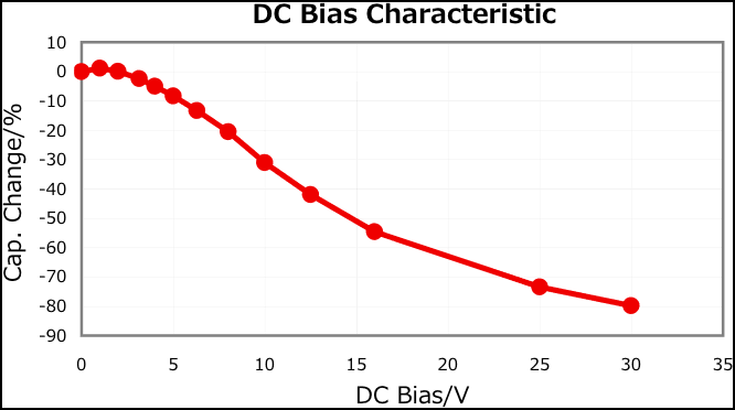
How about some examples so you can see how tricky this is, ok? Here are 2 caps that are both 1206 package and rated at 10uF. The first one is a X7R-type with a 30V rating and the other is a X5R-type with a 50V rating. Which do you think would be better?
![]()
![]() Look closely at the Y-axis. Except for the extra "20 volts" the performance between the two is nearly identical. Okay, so this one stacks up pretty well though the only "performance" you gain with the 50V version is that your cap won't fail at at the lower voltage.
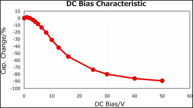
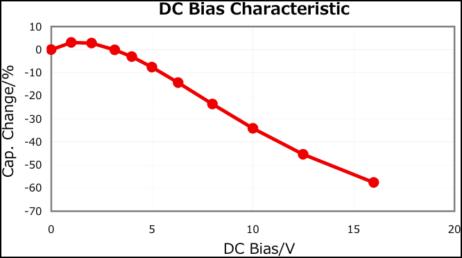
Look closely at the Y-axis. Except for the extra "20 volts" the performance between the two is nearly identical. Okay, so this one stacks up pretty well though the only "performance" you gain with the 50V version is that your cap won't fail at at the lower voltage.Next up is a sample between two 47uF caps, both 1206 package. The first is a X5R-type with a 25V rating, the other is a X7R-type with a 15V rating:
![]()
![]() The difference between these two is dramatic. You might think, "eh, it's 25V and I only need it to smooth a 5V output, should be a piece of cake." At 1/5th it's DC rating, the X5R cap is derated 65% where as the X7R cap is derated only 10%. What you see above is more common difference for the values I needed.
The difference between these two is dramatic. You might think, "eh, it's 25V and I only need it to smooth a 5V output, should be a piece of cake." At 1/5th it's DC rating, the X5R cap is derated 65% where as the X7R cap is derated only 10%. What you see above is more common difference for the values I needed.The trouble is that the smaller your caps, the higher the likelihood that they'll have a poorer electrolytic type. Adding to the pain is that the higher the capacitance value also means higher the likelihood of a poorer electrolytic type. I've spent the better part of 12 hrs just trying to find 4 good caps in decent package sizes for D-DAQ. I even changed the design to actually use higher rated caps because their DC bias derating drops the capacitance to the value I need.
The lesson here is to not take any electrical component for granted. When it comes to MLCC caps, I suggest sticking with Murata or TDK because they both regularly publish the DC Bias graphs. The ones I pulled the screen shots from are from TDK documents. If you happen to have a TDK part number, the extended type with 4 extra digits at the end, paste it to the end of the following URL to get a webpage from them with interactive graphs including DC Bias:
http://product.tdk.com/capacitor/mlcc/detailed_information.php?lang=en&ref=us&part_no=
I so hope your endeavors are a bit less hectic. I'll release another update to D-DAQ and update the BOM shortly.
-MOB
-
Proto v3.6(.5)
07/11/2014 at 06:03 • 0 commentsI'm trending the habit of posting complete change logs here so...
Change log for Proto v3.6:
- Noticed that 2 SSR pairs were engaging in parallel. If a LED burnt out, this would short short the outputs of the 3.3V and 5V rails together. Changed them over to serial engagement and also changed those 2 pair to where the normally closed SSR is first in line so it will disengage first.
- I've dropped in a capacitor on the interconnect to create an RC (100 ohm + 4.7 uF) delay before the NO SSR closes too.
- Thanks to a friendly note of someone else looking over the board files, the input capacitors on the SMPS, C1.1 and C1.2, are greatly inadequate. I did not take into account the capacitance derating with DC offset/bias voltage.
- I'm going to try the TDK CGA8P1X7R1E226M250KC in a US 1812 SMD package. I'll be standing the capacitor on-end. I'll have the chance to subject it to heat and the appropriate voltage and I'll see if a pair will sufficiently smooth the input voltage.
- If that doesn't work, I'll more down to a US 1210 SMD package and stack one of the input capacitors total 3 in parallel.
- Jumped the 3.3V rail over to the digital section of the board to create a full ring for power.
- All components and their footprints have been moved to a singular library this library, Parts for D-DAQ has now been published.
- Please keep in mind that I've altered the standard 0603, 1206, and 1812 footprints based on part measurements in order to facilitate easier clearances. I know it 'breaks' standards :(
- Though nice, the drills from SparkFun and Eagle produce too large of a keepout proportional to the hole size for my tastes. Mounting holes have been adjusted for robber grommets and taking advantage of being positioned in the corners.
Version 3.6.1
- Cleaned up library and merged technologies into 1 device
- Removed extraneous layers on PCB that continued to re-add themselves due to a component having but not needing them.
- Corrected SSR footprints
- Added misc ">Name" silkscreens but have not aligned or sized them yet.
- Files saved under Eagle 6.6.0
Version 3.6.2
- Fixed solder mask alignment for fiducials
Version 3.6.5
- Fixed caps for voltage/capacitance rating and found replacement parts. This board reflects those changes
- Noticed that 2 SSR pairs were engaging in parallel. If a LED burnt out, this would short short the outputs of the 3.3V and 5V rails together. Changed them over to serial engagement and also changed those 2 pair to where the normally closed SSR is first in line so it will disengage first.
-
Warming up the Motors...
07/09/2014 at 20:55 • 0 commentsI picked up a copy of Lucio di Jasio's book for the PIC32's and have read through it a bit. From my past work with some C on 68K's, I already have an idea if the general code structure I'll need. Unfortunately I'm working a 12 hr day today so I may not be up for much when I get home. However, I have 2.5 weeks to get a decent coding platform up and running and define my uC for whichever IDE I choose to use. The PIC32 isn't explicitly defined in many packages so we'll see how it goes. May not hear from me until I have 'Hello HackaDay' outputting on 3 displays and actively refreshing, so it could be a little while.
-
Proto v3.5 & Et al.
07/04/2014 at 10:28 • 0 commentsChange log to the design files
Edit: Parts list reflects v3.5 changes. Link to screen shot of expanded board space.
- Fixed MLP3115 pinout and adjusted footprint for slightly easier soldering
- Fixed MAX4239 SOP-8 footprint
- Removed ICSP header
- Removed associated manual jumpers and pin headers.
- Accelerometer and Ambi. Temp. & Barometer have been relocated due to freed room from bulky pin headers
- roughly centered and reoriented 14 V LDO. Now has a about 3x the amount of copper surrounding it.
- Changed AN pair 6&7 to a flat/right angle uUSB Type A port for reasons stated below and clearances. I've adjusted the maximum sheath clearance of the plugs from 0.25" to 0.28" per plug. Literally spreading things out more than 0.5" on a 5 cm high board with little deficit.
- Added an additional NO and NC, Form-A and Form-B, relays to toggle the power pin on uUSB port for AN input pair 6&7. This pin is now toggled between USB-PWR and MCLR. By using a uUSB type A adapter, the board can be programed via ICSP. Will need to make an adapter and board needs power from a source other than the programmer.
- Changed JTAG to a static, 4-pin pin header. Will need to make an adapter to program. via a "standard" 14-pin cable on a simple breakout board. PTC fuses are 470 ohm and now serve as rudimentary input protection where as v3.4 had none.
You can grab the individual files or a zip of them all from my GitHub account. When I have the chance, I will add up a library for the components and modifications to them, but Eagle does make this an easy task.
I still need to order more parts for the Display Board and stuff some adapter boards. Due to shot stopper problems that have now been fixed in the design, I will not be able to test ambient temperature and pressure or EGTs. I'm considering adjusting the SRAM's footprint and the octal D-latches to allow more pad to show as the pins stick over and I'm using the manufacturer's suggested footprint, which is usually generous, no?
Aside from spending the day on that, I stuffed the QFN SMPS regulator, 5V LDO, PIC32MX795, SRAM, latches, I2C-to-SPI IC, primary oscillator and associated LDO, my SSRs and the uSD card slot. Ended up bending 2 pins on the uC by snagging them with the braid while removing solder bridges, but they didn't break, there is no contact with neighboring pins, and there is no solder bridge. This endeavor was aided by a USB microscope.
![]()
![]()
My Pickit 3 should arrive with my parts on Saturday so I can finish stuffing the board. A few days behind my planned deadline, but not too far off. Unless there is something I missed, this board is complete enough to do the majority of testing I need, though I'll have to make some hard decisions on where or not to order up v3.5 of the prototype or wait until or if I do a redesign for a daughter board power supply subsystem.
I'm still looking at JTAG interfaces. The Flyswatter2. I'm going to be doing pretty quick timing in hardware so getting close to the 40 MHz max JTAG clock on the PIC32 is desired. ICSP is only up to 10 MHz for programming. Either way, work continues and it's time for sleep.
-
D-DAQ Mainboard Design Released!
07/02/2014 at 01:35 • 0 commentsMy sincere apologies if anyone has been waiting for this. I've had work and personal relations come into play so they past 3 days I've needed to put up my files has been next to nil. Right now I'm remoting into my computers at home to make a simple zip file with the CERN OHL of the Eagle schematic capture and board layout and putting that on my server. It's now available on GitHub.
Edit: I've uploaded a new zip file with the OSH Park-compatible DRU and the DSN file for FreeRouting. From this point on, I'll only maintain the GitHub copies.
Zip file MD5: 1d69958143c7c591f87b919347afbcb8
Now, I know it is atypical to use the CERN OHL and something like CC BY-SA to license these files. Unless I've misunderstood their FAQs and other documentation on the CC site, the CC license cannot be revoked once applied to whatever it's applicable to. That and they state that the CC license is not applicable to hardware or software. This may have been a change since version 3; I do not know. I rather stay current instead of having to rely upon a non-current, thus more-likely-to-be-deprecated license to release my design under.
Anyhow, I know the schematic is a bit of a mess and I will clean it up in the near future, but right now that isn't a priority. I'm a bit behind on my work with this and I need to catch back up. I have a vacation coming up soon that will be utilized for much needed rest and this kind of work too. FYI, the SRAM chip does draw a bit of juice, about 80 mA @ 60 MHz iirc, and there are lower power options available. The only issue is that the address pins are different in the TSOP-44 pinout, but the data and control pins are identical.
I've had that version of the board layout running on an offline copy of freerouting.net's software. Why? Some have raised concern about the usefulness of trace length matching that I implemented on the mainboard and, honestly, I have had my doubts about that since I initially set up those traces back in mid February. It is comforting to just a few days later see a HaD article on just this topic. The display driver for the OLED screens favors a 5 ns rise time and so do the data sheets for the PIC32. The re-routed board, which will need some tweaking after the optimizer is done, will have straightened everything out and has dropped the summed trace length on the board from ~156 inches to the low 130's. Also, more than 100 vias have been removed. I very much want to test this resulting copy of the board against the existing design with a home made EMI probe, compare ground plane noise, compare signal skew, see if I need series/source termination on the SRAM, et al. Yes, though I'm running the SRAM at 65 MHz initially, I may attempt a full 80 MHz and see if everything continues to hold together and the speed is beneficial.
Once the accidents clear up I'll make my way home and properly post these files up on GitHub.
-
D-DAQ Mainboard [v3.4] BOM
06/28/2014 at 10:03 • 0 commentsIt's in my links, but in case you don't see it, here is my part list on Mouser that I've been using. I've finished updating it with all of the passives. I do need to make a test version attributing part names to the part, but the actual parts and quantity are accurate for the mainboard revision "Proto 3.4".
Edit: Link removed. There are a few problems with the list and I'm correcting them now. I'll post the link on the main page when it has been corrected.
Since there are still problems with the design, I've not wanted to released it. As it stands:
- The primary issue is that the JTAG TDO pin is tied to the a ground pin on the "JTAG" uUSB receptacle by the ICSP headers. If a cable is plugged into this port, you'll be shorting the TDO pin to ground.
- AN Input uUSB receptacles 6&7, 8&9, 10&11, and 12&13 and too close to each other for a standard cable. As such the connecting cables have to have the jackets of their plugs trimmed to a low profile of about 0.2".
Everything else should be fine, but I won't know until I fully test the prototype etc. After work today, I'll upload the schematic and board layout to GitHub. I need to annotate various portions of work.
From this BOM I'll be able to jot out the Display Boards much more quickly.
-
Design Changes
06/27/2014 at 18:27 • 0 commentsOkay, so honestly I'm attempting to do a large amount of work with D-DAQ being so small. A little ambitious, yes. By nature of that, I've not gone into looking at every fine detail of every component and every function simply because my head would explode.
Today's reason for this post is the MPL3115A: my barometer and ambient temperature sensor. Someone brought to my attention cold junction compensation for my thermocouple connection. I've intentionally not included any circuitry for this and will not use a specialized IC for thermocouples. The latter option is 2x to 4x the cost of the MAX4239 op amp which is more than precise and accurate enough for the job and is a little costly in and of itself. A quick read up on cold junction compensation shows that a thermocouple output is basically a relative measurement between the temperature being measured and the temperature that the amplifier. Well, I'm already measuring the ambient temperature of the mainboard so what's the big deal?
Heh, well, guess what is next to the MPL3115A? My 14V LDO. My hot 14V LDO. I'm considering this the final straw. I'm not going to delay prototyping as a result, but the "final" design of D-DAQs mainboard is going to be moving the power supply subsystem to a separate daughter board that will plug into the backside of the mainboard. I'll be moving to a different SMPS chip, most likely the ZSPM4022, and use and LDO for the 5V rail.
That's back to the original configuration. I previously failed to note that one of my specialized ICs is 3.3V driven, not 5V driven. This leaves just external sensors and various amplifiers needing a 5V supply to avoid rail-to-rail operation and allows software + hardware auto-detection on the sensors to work as well.
Supplementing the redesign drive is the PIC32MX chip. I'm using the 12 mm x 12 mm TQFP packages which requires 7 mil trace with and 7 mil spacing. Advance Circuits charges a premium for anything below 8x8. I originally chose to use this size package to conserve board space due to how small I wanted D-DAQ. Well, there is plenty of room for the 14x14 package. Changing over to the different package requires me to reroute nearly *everything* on the board. I don't have time for that right now, and because it's not a show stopper and the current boards will work, I'm filing this for a later date albeit at a high priority.
Having a 2 board design is conducive to fitting a fan on the final enclosure to help with cooling in really hot environments. As such, there are simply more benefits to this redesign and move to two boards despite the added cost.
 Look closely at the Y-axis. Except for the extra "20 volts" the performance between the two is nearly identical. Okay, so this one stacks up pretty well though the only "performance" you gain with the 50V version is that your cap won't fail at at the lower voltage.
 The difference between these two is dramatic. You might think, "eh, it's 25V and I only need it to smooth a 5V output, should be a piece of cake." At 1/5th it's DC rating, the X5R cap is derated 65% where as the X7R cap is derated only 10%. What you see above is more common difference for the values I needed.